Note: Descriptions are shown in the official language in which they were submitted.
CA 02995989 2018-02-16
WO 2017/063822
PCT/EP2016/072229
- 1 -
MULTIPLE DWELLING CHANNEL STACKING SYSTEM
Technical Field
The present invention generally relates to the field of satellite signal
distribution
systems for multiple dwelling units. More particularly a multiple dwelling
channel
stacking system, for example for distributing satellite TV signals.
Background
[01] In satellite signal distribution systems, there can be made a distinction
between Single Family Units (SFU) that are able to handle distribution of
suitable
signals to one or more receiving devices for an individual user in a single
housing
environment, and Multiple dwelling units (MDU), often also referred to as
multi-
dwelling units, which are able to handle distribution of suitable signals to a
plurality of
dwellings of a plurality of different users, such as for example a plurality
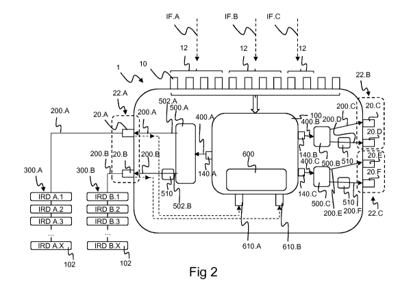
of
apartments or flats or the like in which one or more receiving devices are to
be
provided with suitable signals.
[02] In a typical satellite signal distribution system, one or more satellite
dishes are
provided for capturing the high frequency (RF) satellite signal transmitted by
one or
more satellites. The parabolic shape of the satellite dish reflects the focal
point of the
dish. A feedhorn is mounted at or near this focal point and feeds the RF
satellite signal
by means of a suitably connected waveguide to a low-noise block downconverter
(LNB). The LNB converts the high frequency RF satellite signals from
electromagnetic
waves or radio waves to electrical signals and shifts the signals from for
example the
high frequency C-band, Ku-band, Ka-band, etc. to intermediate frequency (IF)
signals,
for example in the L-band range, which are more suitable for further
distribution, for
example by means of coaxial cables. In a multiple dwelling context typically
each high
frequency RF satellite signal is downconverted by the LNB to four intermediate
frequency (IF) signals, each provided on a separate coaxial cable to a
headend, one
CA 02995989 2018-02-16
WO 2017/063822- 2 -
PCT/EP2016/072229
or more multiswitches, or other suitable distribution devices for further
distribution to
the receiving devices or tuners, such as for example Set Top Boxes (STB),
Personal
video recorders (PVR), etc. , as present in a plurality of dwellings of the
multiple
dwelling unit (MDU).
[03] The high frequency RF satellite signals and their corresponding
downconverted
IF signals comprise a plurality of smaller frequency bands, which are
generally referred
to as transponders or channels, each containing one or more TV, radio or data
channels. For example, in Europe, a Ku band RF satellite signal with a
frequency band
from 10.7 to 12.75 GHz, comprising 2 polarisations, for example a vertical and
a
horizontal polarisation, is used for direct broadcast satellite services such
as those
carried by the Astra satellites. This RF satellite signal for example
comprises a plurality
of transponders with a bandwith of 36MHz of which the center frequencies are
spaced
39Mhz apart. The RF satellite signal is conventionally downconverted by means
of an
LNB to four IF signals comprising a bandwith ranging from about 0.95GHz-
2.15GHz :
a horizontal low band ; a horizontal high band, a vertical low band; and a
vertical high
band. Each of these IF signals comprising the respective plurality of
transponders of
the respective downconverted RF satellite signal frequency range, for example
24
transponders. These four IF signals are connected by means of four coaxial
cables to
the inputs of a distribution device, such as for example a satellite
multiswitch, for further
distribution to receiving devices such as for example Set Top Boxes (STB). If
more
than one RF satellite signal is received, for example by means of a plurality
of satellite
dishes, it is clear that a corresponding plurality of four IF signals and four
extra cables
are needed per RF satellite signal. All these cables are then connected to the
inputs
of a satellite distribution device for further distribution to the receiving
devices. In a
multiple dwelling context distribution devices are often also provided with
cascading
outputs for cascading the received IF signals to the inputs of a further
distribution
device, as each distribution device is only able to serve a predetermined
maximum
number of receiving devices.
[04] A particular category of satellite signal distribution devices are
referred to as
Channel Stacking Switch (CSS), also referred to as SCR (Satellite Channel
Router),
Unicable, OLT (One Line Technology), etc.) operating in a channel stacking
mode.
Such a Channel stacking Switch, also referred to as a Channel Stacking System
in the
CA 02995989 2018-02-16
WO 2017/063822- 3 -
PCT/EP2016/072229
context of this application, is a particular type of a satellite signal
distribution device,
which allows each of the outputs of the distribution device to be connected to
a plurality
of receiver devices by means of a single cable. Additionally each of the
plurality of
receiving devices which is connected to an output of the Channel Stacking
System is
able to select and receive any desired transponder available from the
downconverted
IF signals, independently of the other receiving devices that are connected to
this
single cable. This is achieved by means of the generation of a CSS output
signal, which
comprises a dedicated user band for each of the receivers connected to by
means of
this single cable, as generally known to a person skilled in the art. This
means that
each receiver device that is connected to a single cable is provided with a
dedicated
user band with a bandwidth approximately the same as a transponder, for
example
36MHz. The centre frequencies of each of the user bands of the receiver
devices
connected to a single cable are also spaced at a particular distance, for
example about
100MHz or more for analogue CSS and for example 39MHz or more, or the same
distance as for the transponders, in the case of digital CSS. Further these
centre
frequencies of the user bands of the receiver devices connected to a single
cable are
provided in a frequency range which largely corresponds to the frequency range
of the
received IF signals, such as for example 0.95GHz to 2.15GHz. Each of the
desired
transponders for each of the receiver devices connected to a single cable is
selected
from the respective IF input signal, for example by means of a suitable
filtering
operation, and subsequently frequency translated to the respective user band
centre
frequency assigned to each the requesting receiving device. Finally the user
bands of
each of the requesting receiver devices are combined into a CSS output signal
that is
provided via the single cable to the connected receiver devices, which by each
tuning
into their assigned user band are able to receive the requested transponder.
Several
proprietary and standardised schemes are known in relation to generation of
the CSS
output signal and the related control signals for transponder selection, user
band
allocation, etc. There is for example known a European industry standard for
distributing satellite signals over a single coaxial cable from CENELEC
EN50494,
which has been defined in 2007 and is developed by a consortium led by SES,
which
supports 8 receiving devices connected by means of a single cable to an output
of a
distribution device and selection of transponders from up to 8 downconverted
satellite
IF signals. Recently there is also currently drafted the CENELEC EN 50607
standard
which supports up to a maximum of 32 receiving devices connected by a single
cable
CA 02995989 2018-02-16
WO 2017/063822- 4 -
PCT/EP2016/072229
to an output of the distribution device, and selection of transponders from up
to a
maximum number of 256 downconverted satellite IF signals.
[05] Multiple Dwelling Unit (MDU) CSS distribution devices that were based on
analog technology often required multiple analog channel stacking integrated
circuits
comprising complex analog filtering circuits, programmable mixers for each
user band,
etc and a dedicated microcontroller for implementing the appropriate
communication
protocol for MDU applications in addition. This limited the maximum number of
user
bands that could be achieved, and an increase in the number of user bands led
to a
corresponding increase in power consumption of all analog components. One
known
MDU CSS distribution device is for example the SUS 5581 / 33 NFA LEGACY 63, as
presented in the SPAUN product catalogue, page 50, as retrieved from
http://www.spaun.de/pdf/spaun 17 en.pdf on 17/12/2014, which is able to
provide a
maximum of 8 userbands on a single output, or a maximum of 3 user bands on
three
outputs. The maximum number of available user bands per output is limited by
the
connected analog hardware, this means by means of the number of parallel
analog
frequency paths for each user band, which are physically connected to the
output. In
a first 1x8 CSS configuration the parallel frequency translation paths for the
generation
of 8 user bands are combined into a single output signal. In a second 3x3 CSS
configuration, three distinct outputs, each receive a combined output signal
of a distinct
group of 3 parallel frequency translation paths. The number of maximum
receiving
devices that can be served by each output is thus rather limited and needs to
be
determined by means of the hardware configuration.
[06] Recently components for use in Channel Stacking Systems referred to as
digital
Channel Stacking Systems or digital Channel Stacking Switches (dCSS) have
become
available. For example, Maxlinear provides the MxL86x family of digital
satellite
Channel Stacking Switch, which is provided as a System on Chip (SoCs) or an
integrated circuit (IC) which provides the functionality of most of the
analogue filtering,
frequency translation, etc. components referred to above, by means of a
digital signal
processing integrated circuit. A digitised version of the IF signals, for
example by
means suitable analogue to digital converters (ADC), is provided to the
digital signal
processing circuitry, which generates a digital version of the required CSS
output
signal, that can subsequently be provided in the form of an analog CSS output
signal
CA 02995989 2018-02-16
WO 2017/063822- 5 -
PCT/EP2016/072229
comprising a plurality of userbands to the receiving devices, for example
after
conversion by means of a suitable digital to analog converter (DAC). This
allows the
generation of an increased maximum number of userbands of which the centre
frequencies can be positioned closer to each other as mentioned above, without
the
corresponding increase in power consumption, as there is no longer a need for
a
corresponding increase in parallel analogue frequency translation paths. In
case of the
MxL86x family of dCSS SoC up to a maximum of 24 user bands can be provided. An
alternative dCSS Soc is for example provided by Entropic as the EN5520
integrated
circuit, that is able to provide up to a maximum of 32 user bands. Still a
further dCSS
system that makes use of a Digital Switching and Signal Processing (DSSP)
circuit is
known from W02009/143082. It is clear that such dCSS circuits when used in a
MDU
distribution device provide for an increase in the maximum number of user
bands that
can be provided, a corresponding reduction design complexity, system cost, and
power
consumption.
[07] However, the use of these dCSS circuits as a CSS module in a multiple
dwelling
channel stacking system has led to a new problem, especially when the
generated
user bands need to be distributed via a plurality of CSS output connectors,
each of
these CSS output connectors being connected by means of a single cable to the
receiving devices of a different user in a different dwelling of the multiple
dwelling unit.
Specific difficulties arise in a multiple dwelling context as, because the
number of user
bands provided to an output is no longer limited by the number of analogue
frequency
translation paths, that some of the users claim an unallowable share of the
available
user bands. Further, installation or reconfiguration of receiving devices that
impacts
user band allocation of one dwelling could potentially propagate to the user
band
allocation of receiving devices in another dwelling. Still further as in a
multiple dwelling
context the one, two or three available outputs of the dCSS circuit of the CSS
module
will often be shared amongst a higher number of four, six, eight, ... of
output
connectors, this could give rise to privacy issues as user bands of output
connectors
for different users of different dwellings that are connected to the same
output of the
dCSS circuit will provide a CSS output signal comprising all user bands and
selected
transponders for all the receiving devices of all these different users.
CA 02995989 2018-02-16
WO 2017/063822- 6 -
PCT/EP2016/072229
[08] A system for solving user band allocation issues that could arise in a
Single
Family unit context is for example known from W02012/145220. This system keeps
track of previously assigned user bands and the corresponding receiver
devices. When
a user band request from a new receiver device would result in the need to
provide a
previously assigned user band, it will first be checked with the previous
previously
assigned receiver device of this user band, whether such reallocation is
allowed.
Although such a system, when applied in a multiple dwelling context, could
potentially
reduce the number of user band allocation events that impact another user,
however
this requires all receiver devices of all users to be compatible with this
functionality.
Further, it does not provide a solution to problems mentioned above regarding
to users
claiming an unallowable share of the available user bands, privacy, etc.
Solving the
problem by providing multiple dSSC circuits so that their outputs no longer
need to be
shared between a higher number of output connectors of a MDU CSS system also
leads to an increase in power consumption, design complexity, system cost,
etc.
[09] There has been made available in October 2014 an SES Technical
Recommendations Document titled "Universal Wideband LNB" comprising a
technical
specification for the kind of equipment currently called ASTRA Universal
Wideband
LNB. Such an LNB will, similar as described above be able to receive RF
satellite
signals in a frequency range of 10.70 to 12.75 GHz in horizontal and vertical
polarisation and output downconverted IF signals, which are referred to as
Wideband
IF signals. These wideband IF signals are provided on two IF outputs. A first
output
providing a downconverted IF signal of the entire RF signal in the horizontal
polarisation in the frequency range of 290MHz - 2340 MHz. A second output
providing
a downconverted IF signal of the entire RF signal in the vertical polarisation
in the
frequency range of 290MHz - 2340 MHz. Such a wideband LNB is thus able to
provide
wideband IF signals comprising all transponders by means of two coaxial cables
instead of four cables as described above.
[10] Therefor there still is a need for an improved multiple dwelling channel
stacking
system that overcomes the above mentioned draw backs and is able to provide a
high
number of user bands, with a reduced design complexity, a reduced power
comsumption, a reduced level of propagation of user band allocation issues, an
CA 02995989 2018-02-16
WO 2017/063822- 7 -
PCT/EP2016/072229
increased level of privacy, a reduced risk for claiming an unallowable share
of available
user bands, etc.
Summary
[11] According to an aspect of the invention, there is provided a channel
stacking
system comprising:
- A plurality of CSS output connectors, configured to provide a respective
plurality of
CSS output connector signals to a respective plurality of connected groups of
receivers, each receiver of the connected group of receivers configured to
request a
user band of the CSS output connector signal;
- A CSS module comprising one or more CSS module outputs and configured to
generate for each CSS module output a corresponding CSS module output signal
comprising a set of four or more user bands; and
- At least one CSS output interface configured to respectively couple one
CSS module
output to a corresponding CSS output connector subset comprising two or more
corresponding CSS output connectors, such that each of the corresponding CSS
output connector signals comprises a respective subset comprising two or more
user
bands of the corresponding CSS module output signal, wherein the corresponding
CSS output connector subset comprises a first CSS output connector and at
least one
further CSS output connector:
- the CSS output interface coupled to the first CSS output connector
without frequency
translation; and
- the CSS output interface coupled to the at least one further CSS output
connector via
a respective frequency translation module, which is configured to frequency
translate
the corresponding subset of user bands.
[12] Further advantageous and/or optional embodiments have been defined by
means of the dependent claims.
[13] In this way there is provided a channel stacking system, more
particularly a
multiple dwelling channel stacking system that overcomes the abovementioned
problems, which is able to provide a high number of user bands and distribute
this in a
CA 02995989 2018-02-16
WO 2017/063822- 8 -
PCT/EP2016/072229
fair way amongst the different users in a multiple dwelling context. This is
realised in a
way that multiplies the number of CSS output connectors with respect to the
number
of module outputs of a CSS module. Additionally, this is realised in a way
that enables
the plurality of CSS output connectors of a single CSS module output, to
advantageously manage a plurality of different groups of receivers. Even when
this
single CSS module output was only designed to support a single group of
receivers,
the plurality of CSS output connectors of its corresponding CSS output
connector
subset enable support of multiple groups of receivers in an advantageous way
by
means of the CSS output interface and the frequency translation module. In
this way
a channel stacking system making use of such a CSS module, which is often a
System
on Chip or Integrated Circuit comprising a limited number of CSS module
outputs, is
made more suitable for a multiple dwelling context. Additionally this is
accomplished in
a way that optimizes reduced power consumption as a number of output
connectors
which is a multiple of the number of CSS module output connectors is made
available,
without the need to provide a corresponding multiple of such CSS modules. It
will be
clear from the description that several embodiments are provided which ensure
a
particular simple setup and installation of the multiple dwelling channel
stacking
system, a reduced level of propagation of user band allocation issues, an
increased
level of privacy, a reduced risk for claiming an unallowable share of
available user
bands, etc.
Brief Description of the Drawings
[14] Figure 1 illustrates an embodiment of a multiple dwelling channel
stacking
system according to the invention in a multiple dwelling context;
[15] Figure 2 illustrates the embodiment of the multiple dwelling channel
stacking
system of Figure 1 in more detail;
[16] Figures 3 to 10 illustrate schematically different embodiments of signals
and
correlation tables for use with the multiple dwelling channel stacking system
according
to the embodiments of Figures 1 or 2;
CA 02995989 2018-02-16
WO 2017/063822- 9 -
PCT/EP2016/072229
[17] Figures 11 to 13 schematically illustrate still further embodiments of
the multiple
dwelling channel stacking system; and
[18] Figure 14 schematically illustrates an alternative correlation table for
use with
still a further embodiment of the multiple dwelling channel stacking system.
Detailed Description of Embodiment(s)
[19] Figure 1 shows an embodiment of a multiple dwelling channel stacking
system
1. As shown the multiple dwelling channel stacking system 1 is in use in an
embodiment of an apartment building or the like, which comprises six dwellings
3,
referred to as DW.A to DW.F. These dwellings 3 are for example respective
flats of
different respective users or subscribers of satellite signal services. It is
clear that
alternative embodiments are possible with a different plurality of dwellings 3
than the
six shown in Figure 1, and/or a different multiple dwelling context than for
example the
apartment building shown, as long as the satellite signals need to be
distributed to a
plurality of dwellings of a plurality of different users of satellite signal
services. As will
be explained in more detail below, the multiple dwelling channel stacking
system 1
handles the distribution of suitable signals to the plurality of dwellings 3
of the plurality
of different users. In this way one or more receiving devices 102 arranged in
each of
these different dwellings 3 will be provided with suitable signals from the
multiple
dwelling channel stacking system 1. These receiving devices 102 being for
example
Set Top Boxes (STB), Personal video recorders (PVR), etc.
[20] As shown in Figure 1, there are provided three satellite dishes 4. It is
clear that
according to alternative embodiments one or more satellite dishes 4 could be
provided.
The three satellite dishes 4 respectively capture the high frequency or RF
satellite
signal, transmitted by three corresponding satellites 5. As shown the
satellite referred
to as SAT.A transmits RF satellite signal RF.A. This RF satellite signal RF.A
is reflected
by the parabolic shape of the satellite dish to a feedhorn which feeds the RF
satellite
signal RF.A to a low-noise block downconverter or LNB, referred to as LNB.A in
Figure
1. LNB.A converts the RF satellite signals RF.A received by the satellite dish
4 to
intermediate frequency or IF signals referred to as IF.A. These IF signals
IF.A are
CA 02995989 2018-02-16
WO 2017/063822- 10 -
PCT/EP2016/072229
subsequently provided to the multiple dwelling channel stacking system 1, for
example
by means of suitable coaxial cables.
[21] Figure 4 shows an embodiment of the RF satellite signal RF.A in more
detail.
The embodiment shown corresponds to a European Ku band RF satellite signal
with a
frequency band from 10.7 to 12.75 GHz. As shown this RF satellite signal
comprising
2 polarisations, a vertical polarisation referred to as "RF.A Ve" and a
horizontal
polarisation referred to as "RF.A Hor". Each of these polarisations of the RF
satellite
signal RF.A comprises a plurality of transponders 6. According to the
embodiment
shown, the transponders 6 comprise a bandwith of 36MHz and their center
frequencies
are spaced 39Mhz apart. As already mentioned above, each of these transponders
for
example comprises one or more TV, Radio or data channels of for example direct
broadcast satellite services, such as those carried by the Astra satellites.
It is however
clear that alternative embodiments of RF satellite signals are possible.
[22] As shown in Figure 5, the RF satellite signal RF.A is downconverted by
means
of LNB.A to four IF signals IF.A, each comprising a bandwidth ranging from
about
0.95GHz-1.95GHz or 1,10GHz-2,15GHz. A first IF signal comprises a horizontal
low
band and is referred to as "IF.A Hor-Lo". A second IF signal comprises a
horizontal
high band and is referred to as "IF.A Hor-Hi". A third IF signal comprises a
vertical low
band and is referred to as "IF.A Ver-Lo". A fourth IF signal comprises a
vertical high
band and is referred to as "IF.A Ver-Hi". Each of these four IF signals
comprises the
respective plurality of transponders of the respective downconverted
corresponding
RF satellite signal frequency range as indicated in Figure 4. As shown, the
IF.A Hor-
Lo signal comprises the plurality of transponders in the frequency range of
10,7GHz to
11,7GHz of the RF.A Hor signal. As further shown the IF.A Hor-Hi signal
comprises
the plurality of transponders in the frequency range of 11,7GHz to 12,75GHz of
the
RF.A Hor signal. A similar frequency range is applied for distributing the
transponders
of the RF.A Ver signal to the IF.A Ver-Lo signal and IF.A Ver-Hi signal
respectively.
Each of the four IF.A signals in this way for example comprises 10 or more
transponders 6. It is clear that alternative embodiments are possible in which
for
example alternative RF satellite signals could be downconverted by means of an
LNB
to one or more IF signals, which could for example comprise an alternative
bandwidth
and/or frequency range. Such alternative LNB types are for example known as a
CA 02995989 2018-02-16
WO 2017/063822- 11 -
PCT/EP2016/072229
Standard North America Ku band LNB which downconverts a horizontal and
vertical
linear polarized RF satellite signal in a frequency range of 11.70 GHz ¨ 12.20
GHz to
an intermediate frequency range of 950MHz ¨ 1,450 MHz, or for example a North
America DBS LNB which downconverts a right hand and left hand circular
polarized
RF satellite signal in a frequency range of 12.20GHz ¨ 12.70 GHz to an
intermediate
frequency range of 950MHz ¨ 1,450 MHz, or for example a C-band LNB which
downconverts a horizontal and vertical linear polarized RF satellite signal in
a
frequency range of 3.40 GHz ¨ 4.20 GHz to an intermediate frequency range of
950MHz ¨ 1,750 MHz, etc.
[23] As shown in more detail in Figure 2, which shows the multiple dwelling
channel
stacking system 1 of the embodiment of Figure 1 in more detail, These four
IF.A signals
will be provided by LNB.A to a group 12 of four input connectors 10 of the
multiple
dwelling channel stacking system 1, for example by means of four coaxial
cables. As
shown in Figure 1, the multiple dwelling channel stacking system 1 will then
handle
further distribution to receiving devices 102.
[24] As shown in Figure 1 and 2, the RF satellite signal RF.B received from
satellite
SAT.B and downconverted to intermediate frequency signals IF.B by LNB.B
results,
similar as explained above with reference to RF satellite signal RF.A and
intermediate
frequency signals IF.A, in a corresponding group of four intermediate
frequency signals
IF.B. As shown in Figure 2, these four IF signals IF.B are provided, for
example by
means of four coaxial cables, to a corresponding group 12 of four input
connectors 10
of the multiple dwelling channel stacking system 1 for further distribution to
the
receiving devices 102.
[25] As further shown in Figure 1 and 2, there is still a further RF satellite
signal RF.0
received from satellite SAT.C. According to the embodiment shown, this RF.0
signal
is downconverted to intermediate frequency signals IF.0 by a further LNB
referenced
as LNB.C. LNB.C, different from the universal LNBs LNB.A and LNB.B, according
to
this embodiment is a universal Wideband LNB already mentioned above. Similar
as
described above with reference to RF satellite signal RF.A and shown in Figure
4,
LNB.0 will according to this embodiment receive RF satellite signal RF.A Hor
in a
frequency range of 10.70 to 12.75 GHz in a horizontal polarisation and RF.A
Ver in a
CA 02995989 2018-02-16
WO 2017/063822- 12 -
PCT/EP2016/072229
similar frequency range in a vertical polarisation. However LNB.0 will
downconvert the
RF satellite signal into only two IF signals, instead of four. As shown in
Figure 6, these
intermediate signals "IF.0 Hor-Wi" and "IF.0 Ver-Wi" provided by the universal
wideband LNB LNB.C, are referred to as Wideband IF signals. As shown in Figure
6,
the first wideband IF signal IF.0 Hor-Wi comprises providing a downconverted
IF signal
of the entire RF signal in the horizontal polarisation in the frequency range
of 290MHz
- 2340 MHz. As shown, the IF.0 Ver-Wi signal comprises in a frequency range of
0,29GHz to 1,3GHz all transponders of the RF.0 Hor-Lo frequency range from
10,7GHz to 11, 7GHz. Further the IF.0 Ver-Wi signal also comprises in a
frequency
range of 1,3GHz to 2,34 GHz the transponders of the RF.0 HorHi frequency range
of
11,7GHz to 12,75GHz. Similar, Figure 5 also shows that the IF signal IF.0 Ver-
Wi
comprises the transponders of both frequency ranges RF.0 Ver-Lo and RF.0 Ver-
Hi
in a similar downconverted intermediate frequency range of 0,29GHz to 2,34GHz.
As
shown in Figure 2, such a wideband LNB is thus able to provide wideband IF
signals
IF.0 comprising all transponders of the RF.0 signal to a corresponding group
12
comprising only two input connectors 10, for example by means of two coaxial
cables.
[26] It is clear that alternative embodiments are possible to that shown in
Figures 1
to 6, in which one or more plurality of satellite dishes and corresponding
LNBs for
reception of respective RF satellite signals are provided. According to still
further
embodiments also the amount of universal LNBs and/or universal wideband LNBs
could vary with respect to the embodiment shown. It is clear that for each of
the
universal LNBs coupled to the multiple dwelling channel stacking system 1, the
IF
signals will be provided to a corresponding group 12 of four input connectors
10 and
for each of the universal wideband LNBs coupled to the multiple dwelling
channel
stacking system 1, the IF signals will be provided to a corresponding group 12
of two
input connectors 10, for example by means of a corresponding number of
suitable
coaxial cables. It is clear that still further embodiments are possible in
which one or
more groups of one or more input connectors are connected to any suitable
number of
one or more groups of one or more IF signals provided by one or more, or any
suitable
combination of LNB, such as for example one or more single output LNBs and/or
one
or more multi output LNBS such as for example a dual output LNB, a twin output
LNB,
quad output LNB, an octo output LNB, a Quattro LNB, etc.
CA 02995989 2018-02-16
WO 2017/063822- 13 -
PCT/EP2016/072229
[27] As further shown in Figures 1 and 2, the multiple dwelling channel
stacking
system 1 provides six CSS output connector signals 200 to the six dwellings 3.
Each
of the six CSS output connector signals 200 serves a respective group 300 of
receivers
102 of the subscriber or user of the corresponding dwelling 3. As shown for
example,
CSS output connector signal 200.A provided by the multiple dwelling channel
stacking
system 1 serves a group 300.A comprising a plurality of receiver devices 102,
referred
to as IRD A.1, IRD A.2, etc. of a subscriber associated with the dwelling 3
referenced
as DW.A. As shown in Figure 2, the CSS output connector signal 200.A is
provided by
the multiple dwelling channel stacking system 1 at a CSS output connector 20
referenced as 20.A. Each of the receiver devices IRD A.1, IRD A.2, etc. of the
group
300.A of dwelling DW.A, is able to request a respective user band 110 of the
CSS
output connector signal 200.A. Each of the receiver devices IRD A.1, IRD A.2,
etc. of
the group 300.A of dwelling DW.A will also be able to provide transponder
selection
commands to the multiple dwelling channel stacking system 1, upon which the
multiple
dwelling channel stacking system 1 selects the desired transponder from the
respective IF signals received at the input connectors 10 of the multiple
dwelling
channel stacking system 1. As shown in Figure 2, the plurality of input
connectors 10
are connected to a CSS module 100. As explained above, the CSS module 100 in
this
way receives the plurality of downconverted IF satellite signals IF.A, IF.B,
IF.0
comprising a plurality of satellite transponders from the connected LNBs
LNB.A, LNB.B
and LNB.C. The CSS module 100 will in function of a transponder selection
command
issued by for example receiver device IRD A.1, select the desired transponder
from
these IF satellite signals received from the input connectors 10, and
subsequently
generate the user band 110 assigned to IRD A.1 for the CSS output connector
signal
200.A. Such transponder selection commands generated by the receiver devices
could
for example be encoded according to a protocol based on Digital Satellite
Equipment
Control or DiSEqC. It is clear that alternative protocols are available such
as for
example FSK, which is for example used in the US, or any other suitable
alternative
protocol. With this protocol data signals and power can be transmitted and
received
over a coaxial cable without interfering with the IF satellite signals.
[28] As further shown in Figures 1 and 2 a single CSS output connector signal
200.A
provided at a single CSS output connector 20.A of the multiple dwelling
channel
stacking system 1 is able to serve a group 300.A comprising a plurality of
receiver
CA 02995989 2018-02-16
WO 2017/063822- 14 -
PCT/EP2016/072229
devices IRD A.1, IRD A.2, etc. Similar, as already explained above, the
receiver
devices 102 of this group 300.A are respectively associated with a particular
user band
110 of the CSS output connector signal 200.A and can thus be connected to this
CSS
output connector 20.A by means of a single coaxial cable.
[29] As shown in Figures 1 and 2, similar as explained above with respect to
the group
300.A comprising a plurality of receiver devices 102 of dwelling DW.A, which
are
coupled to CSS output connector 20.A, also the group 300.13 comprises a
plurality of
receiving devices 102 referenced as IRD B.1, IRD B.2, etc of the subscriber
associated
with dwelling DW.B. Similar as explained above output connector signal 200.I3
provided at CSS output connector 20.I3 will allow the receiving devices 102 of
group
300B to receive a selected transponder 6 at a corresponding requested user
band 110.
Similar as explained above the CSS output connector signal 200.13 can be
distributed
to the group 300.13 of receiver devices 102 along a single coaxial cable.
[30] As further shown in Figures 1 and 2, similarly as described above, also
CSS
output connector signals 200.0 ¨ 200.F at CSS output connectors 20.0 ¨ 20.F
respectively provide selected transponders at a requested user band to a
respective
group 300.0 ¨ 300.F of one or more receiver devices 102. It is clear each
group of 300
of receiver devices 102 can be coupled to the respective CSS output connector
20 by
means of a single coaxial cable.
[31] It is clear that alternative embodiments are possible in which the
multiple dwelling
channel stacking system comprises a different number of CSS output connectors
20,
as long as in general the multiple dwelling channel stacking system 1
comprises a
plurality of CSS output connectors 20. These plurality of CSS output
connectors 20
being configured to provide a respective plurality of CSS output connector
signals 200
to a respective plurality of connected groups 300 of receivers 102. Each
receiver 102
of the group 300 of receivers 102 coupled to a particular CSS output connector
20
being configured to request a user band 110 of the CSS output connector signal
200
provided at this particular CSS output connector 20.
[32] As shown in Figure 2, the CSS module 100, which is for example a dCSS
module
as mentioned above, comprises three CSS module outputs 140 referenced as
140.A,
CA 02995989 2018-02-16
WO 2017/063822PCT/EP2016/072229
- 15 -140.13 and 140Ø According to alternative embodiments the CSS module
100 could
comprise a different number of CSS module outputs 140, as long as in general
the
CSS module 100 comprises one or more CSS module outputs 140. As shown in
Figure
7 the CSS module 100 is configured to generate at the CSS module output 140.A
a
corresponding CSS module output signal 400.A. This CSS module output signal
400.A
comprises according to the embodiment shown in Figure 7 a set 120 of ten user
bands
110 referenced as UB1, UB2, ... , UB10. According to this particular
embodiment the
user bands comprise a bandwidth approximately the same as the transponders 6,
for
example 36MHz. The respective centre frequencies of the set 120 of adjacent
user
bands UB1, UB2, ... , UB10, according to this embodiment shown in Figure 7,
are for
example 1000MHZ, 1100MHz, 1200MHz, 1300MHz, 1400MHz, 1500MHz, 1600MHz,
1700MHz, 1800MHz and 1900MHz. However it is clear that according to
alternative
embodiments a different number and distribution of the user bands along the
frequency
spectrum of the CSS module output signal 400.A are possible, as long as in
general
the CSS module 100 is configured to generate a corresponding CSS module output
signal 400.A comprising a set 120 of four or more adjacent user bands 110.
[33] According to the embodiment shown in Figures 2, the CSS module 100 is for
example a dCSS module capable to generate thirty or more user bands for
distribution
along its three CSS module outputs 140. According to such an embodiment the
CSS
module 100 will, similarly as explained above with reference to CSS module
output
140.A, be configured to provide a corresponding CSS module output signal 400
comprising a further set 120 of ten further adjacent user bands 110. Similar
as shown
in Figure 7, the CSS module output 140.13 could provide a corresponding CSS
module
output signal 400.13 comprising a set 120 of ten adjacent user bands UB1 1,
UB12, ...
, UB20 respectively at the centre frequencies 1000MHZ, 1100MHz, 1200MHz,
1300MHz, 1400MHz, 1500MHz, 1600MHz, 1700MHz, 1800MHz and 1900MHz. Also
similar as shown in Figure 7, the CSS module output 140.0 could provide a
corresponding CSS module output signal 400.0 comprising a set 120 of ten
adjacent
user bands UB21, UB22, ... , UB30 respectively at the centre frequencies
1000MHZ,
1100MHz, 1200MHz, 1300MHz, 1400MHz, 1500MHz, 1600MHz, 1700MHz, 1800MHz
and 1900MHz. It is clear that alternative embodiments are possible, as long as
in in
general the CSS module 100 is configured to generate for each CSS module
output
CA 02995989 2018-02-16
WO 2017/063822- 16 -
PCT/EP2016/072229
140 a corresponding CSS module output signal 400 comprising a set 120 of four
or
more adjacent user bands 110.
[34] As further shown in Figure 2, according to this embodiment, the multiple
dwelling
channel stacking system 1 comprises three CSS output interfaces 500,
respectively
coupled to the three CSS module outputs 140 of the CSS module 100. As further
shown these CSS output interfaces respectively couple one CSS module output
140
to a corresponding CSS output connector subset 22 comprising two corresponding
CSS output connectors 20. As shown in Figure 2, according to this embodiment,
CSS
output interface 500.A couples CSS module output 140.A to CSS output connector
subset 22.A comprising two CSS output connectors 20.A and 20.B. Similarly CSS
output interface 500.13 couples CSS module output 140.13 to CSS output
connector
subset 22.6 comprising two CSS output connectors 20.0 and 20.D. Also similarly
CSS
output interface 500.0 couples CSS module output 140.0 to CSS output connector
subset 22.0 comprising two CSS output connectors 20.E and 20.F. It is clear
that
alternative embodiments are possible, as long as in general, the multiple
dwelling
channel stacking system 1 comprises at least one CSS output interface 500
configured
to respectively couple one CSS module output 140 to a corresponding CSS output
connector subset 22 comprising two or more corresponding CSS output connectors
20. In this way the number of CSS output connectors 20 of the multiple
dwelling
channel stacking system 1 is thus a multiple of the number of CSS module
outputs 140
available from the CSS module 100.
[35] According to the preferred embodiment of Figure 2, the output interface
500.A
will generate two interface output signals 502.A and 502.13 from the received
CSS
module output signal 400.A. As shown in Figure 8, the first interface output
signal
500.A comprises the five adjacent user bands UB1 to UB5, which are a subset
220.A
of the set 120 of adjacent user bands UB1 to UB10 of the CSS module output
signal
400.A of Figure 7. As schematically shown in Figure 8, according to this
embodiment
the output interface 500.A accomplishes this by applying a filter with the
schematically
represented filter profile 504.A, for example comprising a cut-off frequency
between
UB5 and UB6, for example at 1,45GHz. It is clear that alternative embodiments
are
possible, as long as in general the output interface 500.A filters the CSS
module output
CA 02995989 2018-02-16
WO 2017/063822- 17 -
PCT/EP2016/072229
signal 400.A such that the interface output signal 502.A comprises a subset
220.A
comprising two or more user bands 110. It is clear that embodiments in which
the
subset 220 comprises a plurality of adjacent user bands 110 of the set 120 of
adjacent
user bands 110 of the CSS module output signal 400 are preferable as this
simplifies
the corresponding design for the filter profile 504 applied by the output
interface 500,
as for example shown in the embodiment of Figures 7 and 8. As further shown in
Figure
8, similarly as explained above with reference to the interface output signal
502.A, the
output interface 500.A generates a further interface output signal 502.13
which
comprises a further subset 220.13 comprising the five further user bands UB6
to UB10
of the set 120 of adjacent user bands UB1 to UB10 of the CSS module output
signal
400.A of Figure 7. As schematically shown in Figure 8, according to this
embodiment
this is accomplished by the output interface 500.A by applying a filter with
schematically
represented filter profile 504.B, which for example also comprises a cut-off
frequency
in between UB5 and UB6, for example at 1,45 GHz. It is clear that alternative
embodiments are possible, as long as in general the output interface 500.A
filters the
CSS module output signal 400.A such that the interface output signal 502.13
comprises
a subset 220.13 comprising two or more user bands 110 which are not present in
the
subset 220.A. It is clear that embodiments in which the subset 220 comprises a
plurality
of adjacent user bands 110 of the set 120 of adjacent user bands 110 of the
CSS
module output signal 400 are preferable as this simplifies the corresponding
design for
the filter profile 504 applied by the output interface 500, as for example
shown in the
embodiment of Figures 7 and 8. As shown in Figure 2, each of the interface
outputs
providing the respective interface output signals 502.A and 502.13 of the
output
interface 500.A is respectively coupled to a corresponding CSS output
connector 20.A
and 20.B. It is clear that in this way the output interface 500.A is coupled
to the two
CSS output connectors 20.A and 20.13 of the CSS output connector subset 22.A.
It is
clear that alternative embodiments are possible, for example comprising a CSS
output
connector subset 22.A comprising three or more CSS output connectors, or in
which
the output interface 500 assigns a different distribution of subsets of
adjacent user
bands to the respectively coupled output connectors, as long as in general the
output
interface 500.A is configured to respectively filter the CSS module output
signal 400.A,
such that each of the CSS output connector signals 200.A, 200.13 of the CSS
output
connectors 20.A, 20.13 of the corresponding CSS output connector subset 22.A
only
CA 02995989 2018-02-16
WO 2017/063822- 18 -
PCT/EP2016/072229
comprises a corresponding subset 220.A, 220.13 of two or more adjacent user
bands
110.
[36] As shown in Figure 2, the first CSS output connector 20.A is coupled to
the CSS
output interface 500.A without frequency translation, while the further CSS
output
connector 20.13 of this CSS output connector subset 22.A is coupled to the CSS
output
interface 500.A via a frequency translation module 510.A. As shown, according
to this
embodiment, the frequency translation module 510 shifts the centre frequencies
of the
interface output signal 502.13 downwards by 0,5 GHz such that the centre
frequencies
of UB6 to UB10, which are respectively 1500MHz, 1600MHz, 1700MHz, 1800MHz and
1900MHz are shifted to 1000MHZ, 1100MHz, 1200MHz, 1300MHz, 1400MHz. As
clearly shown in Figure 9, in this way the output interface 500 and the
frequency
translation module 510 cooperate to provide at both CSS output connectors 20.A
and
20.13 of the CSS output connector subset 22.A, which is coupled to the CSS
module
output 140.A via the output interface 500.A, corresponding CSS output
connector
signal 200.A and 200.B, each comprising a corresponding subset 220.A and
220.13 of
five user bands UB1 to UB5 and UB6 to UB10 of which the centre frequencies
respectively match. This means that the CSS output connector signal 200.B of
the
further CSS output connector 20.13 comprises UB6 to UB10 at centre frequencies
of
respectively 1000MHZ, 1100MHz, 1200MHz, 1300MHz, 1400MHz, which match the
centre frequencies of the of the user bands UB1 to UB5 of the CSS output
connector
signal 200.A of the first CSS output connector 20.A of the output connector
subset
22.A.
[37] According to the embodiment shown in Figure 2, the further output
interfaces
500.13 and 500.0 which couple the CSS module output 140.13 and 140.0
respectively
to their corresponding first CSS output connector 20.0 and 20.E without
frequency
translation and to their corresponding further CSS output connector 20.D and
20.F via
a respective frequency translation module 510, generally operate in a similar
way as
described above respectively for UB11 to UB20 and UB21 to UB30. It is clear
that
according to this embodiment the multiple dwelling channel stacking system 1
is able
to provide for six CSS output connector signals 200 at six corresponding CSS
output
connectors 20 which each comprise a subset 220 of five adjacent user bands 110
of
which the centre frequencies match. This means, according to this embodiment
that
CA 02995989 2018-02-16
WO 2017/063822- 19 -
PCT/EP2016/072229
the centre frequencies of the five adjacent user bands of each CSS output
connector
signal 200 are respectively 1000MHZ, 1100MHz, 1200MHz, 1300MHz and 1400MHz.
It is clear that alternative embodiments are possible as long as in general
the multiple
dwelling channel stacking system 1 comprises at least one CSS output interface
500
configured to respectively couple one CSS module output 140 to a corresponding
CSS
output connector subset 22 comprising two or more corresponding CSS output
connectors 20, such that each of the corresponding CSS output connector
signals 200
comprises a respective subset 220 comprising two or more user bands 110 of the
corresponding CSS module output signal 400 of this CSS module output 140.
Whereby
this corresponding CSS output connector subset 22 comprises a first CSS output
connector 20.A, and the CSS output interface 500 is coupled to this first CSS
output
connector 20.A without frequency translation. And whereby this corresponding
CSS
output connector subset 22 also comprises at least one further CSS output
connector
20.B. The CSS output interface 500 being coupled to this at least one further
CSS
output connector 20.13 via a respective frequency translation module 510. This
frequency translation module 510 is configured to frequency translate the
corresponding subset 220.13 of the user bands 110 for the CSS output connector
signal
200.B for this further CSS output connector 20.B. Preferably this frequency
translation
functions to frequency translate this corresponding subset 220.B, such that
the centre
frequencies of its user bands 110 match the centre frequencies of the user
bands 110
of the subset 220.A of the first CSS output connector signals 200A for the
first CSS
output connector 20.A.
[38] It is clear that in this way the output interface 500 couples one CSS
module
output 140.A to a corresponding CSS output connector subset 22.A comprising
two or
more corresponding CSS output connectors 20. As described in more detail above
the
output interface 500 provides this coupling in such a way that each of the
corresponding CSS output connector signals 200 comprises a respective subset
220
comprising two or more adjacent user bands 110 of the corresponding CSS module
output signal 400. According to alternative embodiments the frequency
translation
module 510 could be comprised within the output interface 500.
[39] According to advantageous embodiments, similar to that described with
reference to Figure 2, preferably each of the subsets 220 comprises an
identical
CA 02995989 2018-02-16
WO 2017/063822- 20 -
PCT/EP2016/072229
number of adjacent user bands 110 as this leads to a particularly simple and
efficient
setup for providing a fair distribution of the user bands to each of the CSS
output
connectors 20 of a multiple dwelling channel stacking system 1. Still further,
according
to advantageous embodiments, similar to the embodiment described with
reference to
Figure 2, preferably the centre frequencies of the adjacent user bands of the
subsets
220 of each of the one or more respective first CSS output connectors 20.A,
20.13 and
20.D match. It is clear that in this way at each of the CSS output connects 20
there will
be provided not only an identical number of user bands, but they will also be
provided
at the same centre frequencies, which leads to a particular simple and
efficient
implementation that not only provides for a fair distribution of the user
bands, but also
provides an identical frequency spectrum at each of the CSS output connectors
of the
multiple dwelling channel stacking system 1. However it is clear, as will be
explained
in more detail below with reference to Figure 10 that alternative embodiments
are
possible.
[40] In order to ensure the fair distribution of user bands and allow for the
same
frequency spectrum at the CSS output connectors in an efficient and reliable
way
preferably the multiple dwelling channel stacking system comprises five or
less, for
example three or less, CSS module outputs 140 and respectively two or more CSS
output connectors 20 coupled to each CSS module output 140 via the CSS output
interface 500. This also allows the CSS module 100 to make use of existing
chipsets,
such as for example the dCSS modules mentioned above, which are developed for
Single Family Unit systems without the need for designing a dedicated chipset
for a
multiple dwelling unit.
[41] Preferably, as shown in Figure 2, the CSS module 100 comprises a user
band
correlation module 600. This user band correlation module 600 comprises a
predetermined correlation between each CSS module output 140, which is
represented as column "CSS-OC" in the embodiment of Figure 3, and a
corresponding
set 120 of four or more user bands 110. In the embodiment of Figure 3 this
represented
in column "UB set", and as shown there are for example two lines correlated to
CSS
module output 140.A, namely UB1-UB5 and UB6 ¨ UB10, thereby providing a
correlation between CSS module output 140.A and the set 120 of adjacent user
bands
UB1 to UB10 as explained in more detail above with reference to embodiment of
CA 02995989 2018-02-16
WO 2017/063822- 21 -
PCT/EP2016/072229
Figures 1 and 2. Similarly the embodiment of Figure 3 defines a correlation
between
CSS module output 140.13 and the set of adjacent user bands UB11 to UB20, and
a
correlation between CSS module output 140.0 and the set of adjacent user bands
UB21 to UB30. Additionally the user band correlation module 600 also comprises
a
correlation, respectively for each CSS module output 140, between each CSS
output
connector 20 of its CSS output connector subset 22 and a corresponding subset
220
comprising two or more user bands 110 of the set 120 of four or more user
bands 110
of the CSS module output 140. According to the embodiment shown in Figure 3,
this
correlation is defined for both CSS output connectors 20.A and 20.13 of the
CSS output
connector subset 22.A of CSS module output 140.A, by means of the entries in
the
column "00" and the corresponding entries in the column "UB set". As shown in
Figure
3, this allows, in a simple and efficient way, to define a correlation between
CSS output
connector 20.A and the corresponding subset 220 of user bands UB1-UB5 and a
further correlation between CSS output connector 20.13 and the corresponding
subset
220 of user bands UB6-UB10. It is clear that still further embodiments than
that of the
lookup table of Figure 3 are possible for the user band correlation module
600, as long
as in general both correlations as mentioned above are provided for. It is
further clear
that this also allows for alternative embodiments, in which no filtering is
applied by the
CSS output interface 500 to the set 120 of user bands of the CSS module output
signal
140. In such embodiments each of the CSS output interface output signals will
comprise in addition to the corresponding subset 220 of user bands 110
correlated to
its corresponding CSS output connector, also further user bands of the set 120
of the
CSS module output signal 140. Also these further user bands of the set 120
will be
available to the respective output connector 20. The first output connector 20
of the
group 22 will receive its subset and any further user bands without frequency
translation. The one or more further output connectors of the group will
receive their
corresponding subset and any further user bands after frequency translation is
applied
by means of the frequency translation module 510. As explained above, the user
band
correlation module 600 will then ensure that the control signals received at
the
respective CSS output connector 22 of a group 22 will limit control signals,
for example
for channel selection and/or user band assignment, to the user bands
correlated with
this particular output connector.
CA 02995989 2018-02-16
WO 2017/063822- 22 -
PCT/EP2016/072229
[42] As further shown in Figure 3, according to this embodiment the user band
correlation module 600 further comprises also a correlation between the
respective
CSS output connector and the frequency translation applied by the respective
frequency translation module 510. As shown, for each of the further CSS output
connectors 20.B, 20.D and 20.F of the embodiment of Figure 2, the applied
frequency
translation of 0,5GHz to the subset 220 of adjacent user bands mentioned in
column
"UB set" is mentioned in the corresponding row of column "Freq Trans". This
allows for
example the user band correlation module 600 to provide for a suitable setting
for
operation of the frequency translation module 510, for example under control
of the
CSS module 100 and/or the CSS output interface 500. This is also advantageous,
as
in this way the CSS module 100 is aware of the frequency translation to which
this
particular subset of adjacent user bands of a respective CSS module output
signal 400
is subjected. This is particularly advantageous when handling for example
control
signals respectively received from each the CSS output connectors of a CSS
output
connector subset coupled to a particular CSS module output 140 of the CSS
module
100. As shown in the embodiment of Figure 2 preferably such control signals,
which
are shown in striped lines are respectively fed to a separate control signal
input 610A
and 610B of the CSS module 100, one for each CSS output connector 20.A and
20.B.
Such control signals could for example be transponder selection commands
generated
by the receiver devices, for example encoded according to a protocol based on
Digital
Satellite Equipment Control or DiSEqC. In this way the CSS module 100, even
when
a plurality of CSS output connectors 20 is coupled to a single CSS module
output 140
by means of the output interface, can easily determine from which particular
CSS
output connector 20 the control signal was received. This then allows, for
example by
means of the user band correlation module 600, to determine in an efficient
and robust
way which particular user band or subset of user bands the control signal
refers to. It
also enables to ensure that each output connector signal is not assigned more
than its
correlated number of user bands and in this way allows for a robust and
efficient
distribution of the overall number of user bands in a multiple dwelling
context. It also
ensures that receiver devices cannot perform control operations on user bands
assigned to another CSS output connector than the one the receiver device is
connected to.
CA 02995989 2018-02-16
WO 2017/063822- 23 -
PCT/EP2016/072229
[43] It is clear that still further alternative embodiments are possible than
those
described above with reference to Figures 1 to 9. These will be explained with
reference to Figure 10, which shows an alternative lookup table, similar to
that of the
embodiment of Figure 3, for use by user band correlation module 600. As shown
there
is defined a correlation between the CSS module output 140.A and a set 120
user
bands UB1-UB9 and UB11 for the module output signal 400. It is thus not
required that
all user bands of the set 120 for the respective module output signal 400 are
adjacent
and or distributed along the frequency domain in a uniform or equidistant way,
as long
as in general the CSS module 100 is configured to generate for each CSS module
output 140 a corresponding CSS module output signal 400 comprising a set 120
of
four or more user bands 110. As further shown in the embodiment of Figure 10
there
is defined a correlation between the first CSS output connector 20.A and the
further
CSS output connector 20.13 of the CSS output connector subset 22.A. The first
CSS
output connector 20.A is correlated to the subset 220.A of user bands UB1,
UB2, UB4,
UB5, UB6 and UB7. The further CSS output connector 20.13 is correlated to the
subset
220.13 of user bands UB3, UB8, UB9, UB1 1. It is thus clear that in general
the number
of user bands of both subsets 220.A and 220.13 does not need to be identical
and that
all user bands of each subset 220.A do not need to be adjacent and/or
distributed
along a frequency domain in a uniform or equidistant way, as long as in
general at
least one CSS output interface 500 is configured to respectively couple one
CSS
module output 140 to a corresponding CSS output connector subset 22 comprising
two or more corresponding CSS output connectors 20, such that each of the
corresponding CSS output connector signals 200 comprises a respective subset
220
comprising two or more user bands 110 of the corresponding CSS module output
signal 400.
[44] UB1 ¨ UB9 and UB11 of the CSS module output signal 400.A of the CSS
module
output 140.A, could for example be arranged similarly as mentioned above, at
the
respective centre frequencies of 1000MHZ, 1100MHz, 1200MHz, 1300MHz,
1400MHz, 1500MHz, 1600MHz, 1700MHz, 1800MHz and 2000MHz. The subset
220.A which will be provided without frequency translation to the first CSS
output
connector 20.A as the CSS output connector signal 200.A will thus comprise
corresponding centre frequencies 1000MHZ, 1100MHz, 1300MHz, 1400MHz,
1500MHz, 1600MHz. The CSS output interface 500.A output signal 510.13 will
CA 02995989 2018-02-16
WO 2017/063822- 24 -
PCT/EP2016/072229
comprise a subset 200.13 of user bands comprising centre frequencies of
1200MHz,
1700MHz, 1800MHz and 2000MHz. According to the embodiment of Figure 10 the
subset 200.13 of userbands will be frequency translated with 0,15GHz. This
will result
in a CSS output connector signal 200.13 for the further CSS output connector
20.13 with
a frequency translated corresponding subset 220.13 of 1050MHZ, 1550MHz,
1650MHz
and 1850MHz. Although as described above with reference to Figure 3, it is
preferred
that the respective centre frequencies of the adjacent user bands of the
subsets 220
of each of the one or more respective first CSS output connectors 20.A match,
this
means in case of an identical number of user bands that all user bands match
or in
case of non-identical number of user bands the user bands of the smallest
subset
match with a corresponding number of user bands of the largest subset, it is
clear that
alternative embodiments are possible, as long as in general the CSS output
interface
500 is coupled to at least one further CSS output connector 20.13 via a
respective
frequency translation module 510, which is configured to frequency translate
the
corresponding subset 220.13 of adjacent user bands 110. Although it is
preferred to
operate the frequency translation module such that the frequency range of the
subset
220.13 of user bands 110 of the respective corresponding further CSS output
connector
20.13 matches the frequency range of the subset 220.A at the first CSS output
connector 20.A, according to the embodiment of Figure 10, in general it can
also be
advantageous when the rate of overlap of these frequency ranges is increased
by
means of the frequency translation module 510. Although it is preferred to
operate the
frequency translation module 510 such that the frequency ranges of the
frequency
translated subset 220.13 at the CSS output connector 20.13 and the subset
220.A at the
CSS output connector 20.A overlap completely, such as for example shown in
Figure
9, it is clear from the embodiment of Figure 10 that it could already be
advantageous
when these frequency ranges at least partially overlap. It is clear that still
further
embodiments are possible in which the frequency translation results in a
reversal of
the sequence of the user bands in a subset 220. For example, when in the
example
described above the subset 200.13 of user bands comprising centre frequencies
of
1200MHz, 1700MHz, 1800MHz and 2000MHz would be frequency translated with
2900MHz, this would result in a frequency translated subset 220 of user bands
with
respective centre frequencies 1700MHz, 1200MHz, 1100MHz and 900MHz.
CA 02995989 2018-02-16
WO 2017/063822- 25 -
PCT/EP2016/072229
[45] It is clear that still further embodiments of the multiple dwelling
channel stacking
system 1 are possible. According to such embodiments the multiple dwelling
channel
stacking system 1 further comprises also a plurality of cascade output
connectors 30.
These cascade output connectors 30 are respectively coupled to the plurality
of input
connectors 10 of this multiple dwelling channel stacking system1. The cascade
output
connectors 30 function is to cascade the plurality of downconverted IF
satellite signals
to a further multiple dwelling channel stacking system 1, thereby still
further increasing
scalability in a multiple dwelling context. This is realised, as shown in
Figures 11 and
12, by connecting these cascade output connectors 30, for example by means of
suitable coaxial cables to corresponding input connectors 10 of a subsequent
multiple
dwelling channel stacking system 1. An embodiment comprising such cascade
output
connectors 30 are for example schematically shown in Figures 11 and 12. The
other
elements of the multiple dwelling channel stacking system 1 could in general
be similar
as described above and are not explicitly repeated in the drawings and this
description
for the sake of brevity. As shown the embodiment of Figures 11 and 12
comprises ten
CSS output connectors 20, referenced as 20.1 to 20.10. Similar as described
above
these CSS output connectors 20 can each be provided with a suitable CSS output
connector signal 200 by a CSS module 100. The CSS output connector signal 200
provided by such a CSS module 100 to the CSS output connectors, similar as
described above, comprises a plurality of user bands with respective centre
frequencies that are in a similar range as the downconverted IF satellite
signals. As for
example shown in Figures 9, according to the embodiment shown, the centre
frequencies of the user bands 110 are in an intermediate frequency range which
is
higher than 0,95GHz, for example 0,95GHz to 2,15 GHZ. However it is clear that
alternative intermediate frequency ranges for the user bands could be used,
such as
for example 0,3 GHz to 3GHz or any other suitable intermediate frequency range
for
the user bands.
[46] As shown in the embodiment of Figures 11 and 12, in addition to the
intermediate
frequency satellite signals IF.A, IF.B, IF.0 , received at input connectors
10, the
multiple dwelling channel stacking system 1 further can also receives a signal
from a
terrestrial broadcasting service at a terrestrial input connector 40. The
multiple dwelling
channel stacking system 1 further can also comprises a cable input connector
42 for
receiving an input signal from a cable distribution network. Although in the
embodiment
CA 02995989 2018-02-16
WO 2017/063822- 26 -
PCT/EP2016/072229
described below reference will be made to the terrestrial broadcasting service
and
cable distribution network respectively, it is clear that alternative
embodiments are
possible, as long as in general multiple dwelling channel stacking system 1
comprises
such a first input connector 40 configured to receive a first input signal
from a first
distribution network and such a second input connector 42 configured to
receive a
second input signal from a second distribution network. The frequency range of
the
incoming signal 910 of such a terrestrial broadcasting service, which is for
example
captured by means of a suitable antenna, as shown in Figure 11 is below the
frequency
range of the intermediate frequency satellite signals, for example below
0,9GHz, for
example in the range of 47MHz to 862MHz. The multiple dwelling channel
stacking
system 1, as will be described in more detail below is thus able to distribute
this
terrestrial input connector signal, received at the terrestrial input
connector 40 to each
of its CSS output connectors 20.1, for further distribution together with the
respective
CSS output connector signal 200 generated by the CSS module 100. It is clear
this is
possible because the frequency ranges of the terrestrial input connector
signal and the
CSS output connector signal 200 generated by the CSS module 100 do not
overlap.
Similarly as explained above, with reference to the terrestrial input signal
910,
alternatively a cable input signal 930 originating from for example a cable
television
distribution network or a network of a cable distribution internet service
provider, such
as for example shown in the embodiment of Figure 12, operates in a frequency
range
below the frequency range of the intermediate frequency satellite signals, for
example
below 0,9GHZ, for example in the range of 40MHz to 900MHz. Similarly as
explained
above, this cable input signal 930, when received at the cable input connector
42 can
be distributed by the multiple dwelling channel stacking system 1 to the CSS
output
connectors 20 along with the CSS output connector signals 200 provided by the
CSS
module 100 as their frequency ranges do not overlap. It is clear that
alternative non-
overlapping frequency ranges are possible for the frequency range of the
terrestrial or
cable input signals and respectively the frequency range of the CSS output
connector
signals 200 comprising the user bands originating from the satellite
distribution
network. For example the frequency range of the cable or terrestrial input
signals could
for example be lower than 1002MHz or lower than 1218MHz; and the frequency
range
for the centre frequencies of the user bands of the CSS connector output
signal 200
could for example be respectively higher than 1002MHz or higher than 1218MHz.
CA 02995989 2018-02-16
WO 2017/063822- 27 -
PCT/EP2016/072229
[47] Figures 11 and 12 show an embodiment of the multiple dwelling channel
stacking
system 1 comprising a terrestrial input connector 40 suitable for receiving
input signals
from a terrestrial broadcast service or the like and a cable input connector
42 suitable
for receiving input signals from a cable distribution network or the like.
Figure 11 shows
this embodiment of the multiple dwelling channel stacking system 1 according
to a first
mode of operation wherein the terrestrial input connector 40 receives an input
signal
910 from a terrestrial distribution network. Figure 12 shows this embodiment
of the
multiple dwelling channel stacking system 1 according to a second mode of
operation
wherein alternatively the cable input connector 42 receives an input signal
930 from a
cable distribution network.
[48] As further shown in Figures 11 and 12, the multiple dwelling channel
stacking
system 1, next to the cascade output connectors 30 for cascading the IF
satellite
signals to a further multiple dwelling channel stacking system 1, as
schematically
shown, also comprises a terrestrial cascade output connector 50. This
terrestrial
cascade output connector 50 functions to cascade the input signal 910 received
at the
terrestrial input connector 40 from the terrestrial distribution network to a
further
multiple dwelling channel stacking system 1. The embodiment of the multiple
dwelling
channel stacking system 1, as shown, further also comprises a distribution
module 800
and a distribution module configurator 810 coupled to this distribution module
800.
[49] The distribution module configurator 810 provides a signal to the
distribution
module 800 indicative of whether the input signal originates respectively from
the
terrestrial input connector 40 or the cable input connector 42. According to a
particularly simple embodiment the distribution module configurator 810 could
comprise a suitable manual switch comprising a plurality of selectable states
for
manually selecting whether the input signal originates from a terrestrial
broadcasting
service connected provided to the terrestrial input connector 40 or
alternatively whether
the input signal originates from a cable distribution network provided to the
cable input
connector 42. It is clear that alternative embodiments are possible, in which
for
example the distribution module configurator 810 is able to automatically
determine if
the input signal is received from the terrestrial input connector 40 or the
cable input
connector 42, and/or whether it relates to a signal received from a
terrestrial
broadcasting service, or whether it relates to a signal from a cable
distribution network
CA 02995989 2018-02-16
WO 2017/063822- 28 -
PCT/EP2016/072229
of for example a cable television provider or a cable internet service
provider. The
terrestrial distribution network could for example be a Digital Video
Broadcasting or
DVB terrestrial broadcasting service, such as for example DVB-T or DVB-T2. The
cable distribution network could for example DVB-C, which stands for "Digital
Video
Broadcasting ¨ Cable, or DVB-C2.
[50] As shown terrestrial input connector 40 is coupled to the terrestrial
cascade
output connector 50. By means of a branch module 820 a share of the signal
power of
the input signal of the first input connector 40 is provided to the
distribution module
800. As shown, also the cable input connector 42 is coupled to the
distribution module
800. It is clear that in this way the distribution module 800 is coupled to
the terrestrial
input connector 40 for receiving a share of the signal power of the
terrestrial input signal
of which another share is also cascaded to the terrestrial cascade output
connector
50, and alternatively coupled to the cable input connector 42 for receiving a
cable input
signal from the cable input connector 42. As further shown, the distribution
module 800
is further also coupled to the plurality of CSS output connectors 20 for
distributing the
received terrestrial input signal or cable input signal to the plurality of
CSS output
connectors 20.
[51] As shown in Figure 11, in the first mode of operation, the branch module
820 is
configured to extract 10% of the signal power of the input signal received at
the branch
module 820. This means that 10% from the signal power of the input signal
which
arrives at the branch module 820 is extracted from the coupling between
terrestrial
input connector 40 and the terrestrial cascade output connector 50. This then
allows
the distribution module 800 to distribute respectively 1 % of the signal power
of the
terrestrial input signal received at the terrestrial input connector 40 to
each of the ten
CSS output connectors 20. As shown, 90% of the signal power of this input
signal is
not extracted by the branch module 820 from this coupling and serves to
distribute a
sufficiently large share of the available signal power to the terrestrial
cascade output
connector 50. In this way a large enough share of the power of the input
signal received
from the terrestrial input connector 40 at the branch module 820 is not
extracted and
is distributed from the branch module 820 towards the corresponding
terrestrial
cascade output connector 50 in order to allow for subsequent cascading of to a
further
terrestrial input connector 40 of a further multiple dwelling channel stacking
system 1
CA 02995989 2018-02-16
WO 2017/063822- 29 -
PCT/EP2016/072229
as shown, without the need for intermediate amplification. In this way a
cascade
comprising a cascaded chain of a plurality of such multiple dwelling channel
stacking
systems 1 with a reduced need for intermediate amplification. In this way for
example
five to ten cascaded multiple dwelling channel stacking systems 1 can provide
for a
high level of scalability while providing for a simple set up and a minimal
amount of
cabling to be used to enable distribution of the terrestrial input signal in a
multiple
dwelling context. As shown in the embodiment of Figure 11, such a distribution
ratio is
possible as the input signals 910 from a terrestrial broadcasting service, for
example a
terrestrial television broadcasting service, received by means of suitable
antenna, can
be subjected to a suitable amplification, for example by means of a suitable
amplifier
920 which is coupled upstream of the terrestrial input connector 40 of the
first multiple
dwelling channel stacking system 1 of the cascaded set. Such initial
amplification of
such terrestrial input signals 910 is possible as the terrestrial broadcast
services are
unidirectional, which means that only reception of the terrestrial input
signal 910 is to
be provided for, without the need for any broadcast functionality, a control
channel, an
upload channel, etc. from the receiver devices connected to the CSS output
connectors 20 via the multiple dwelling channel stacking system 1 back to the
terrestrial distribution network.
[52] As shown in Figure 12, when alternatively there is provided an input
signal 930
coupled to cable input connector 42 originates from a cable distribution
network, there
is often the need to provide for broadcast functionality, a control channel,
an upload
channel etc. from the receiver devices connected to the CSS output connectors
20 via
the multiple dwelling channel stacking system 1 back to the cable distribution
network.
In such a context an initial amplification of the cable input signal 930 is
complex as this
interferes with the need to provide for example such an upload channel for the
services
provided by a cable internet service provider. As shown in Figure 12
preferably, the
cable input signal 930 is distributed to each respective cable input connector
42 of the
respective cascaded multiple dwelling channel stacking systems 1 in parallel,
for
example by means of a suitable signal splitting module 940. As further shown,
preferably the cable input connector 42 is not coupled to a corresponding
cascade
output connector. Although this results in the use of more cables for the
distribution of
the cable input signal 930 along the cascaded multiple dwelling channel
stacking
systems 1, the signal power loss resulting at each stage from a cascaded setup
would
CA 02995989 2018-02-16
WO 2017/063822- 30 -
PCT/EP2016/072229
lead to unacceptable low levels of signal power at the respective cable input
connectors 42 of the most downstream cascaded systems without the possibility
to
apply intermediate amplification in a simple way because of for example the
need for
an upload channel. As shown in the embodiment of Figure 12 the distribution
module
800 will receive all signal power from the input signal at the cable input
connector 42.
As further shown in Figure 12, the distribution module configurator 810 will
then
selectively operate the distribution module 800 according a second mode of
operation.
As shown in this second mode of operation the signal power of the input signal
is
distributed entirely by the distribution module 800 to the plurality of CSS
output
connectors 20. As shown in this embodiment the distribution module 800
distributes
respectively 10% of the signal power of the cable input signal received from
the cable
input connector 42 at the distribution module 800 to each of the ten CSS
output
connectors 20. It is clear that according to this embodiment no signal power
of this
cable input signal is wasted to a cascade output connector. In this way a
maximum
amount of the signal power of the unamplified cable input signal received from
the
cable input connector 42 at the distribution module 800 is distributed to the
CSS output
connectors 20, while no signal power is wasted to a corresponding cascade
output
connector, which in such a context is not used.
[53] It is clear that alternative embodiments to that of Figures 11 and 12 are
possible,
as long as in general the distribution module 800 configured to operate
according to a
first mode of operation when the signal from the distribution module
configurator 810
indicates that the input signal 910 originates from the first input connector
40. In this
first mode of operation the first input connector 40 is coupled to a first
cascade output
connector 50 and a branch module 820 provides a share of the signal power of
the
input signal of the first input connector 40 to the distribution module 800.
The
distribution module 800 then distributes this received input signal such that
the share
of the signal power of this input signal received at the first cascade output
connector
50 is larger than the share of the signal power of the input signal provided
to the
distribution module 800 by the branch module 820 for distribution to the
plurality of
CSS output connectors 20. Additionally in general the distribution module 800
is also
configured to operate according to a second mode of operation when the signal
from
the distribution module configurator 810 indicates that the input signal
originates from
the second input connector 42. In this second mode of operation the
distribution
CA 02995989 2018-02-16
WO 2017/063822- 31 -
PCT/EP2016/072229
module 800 will distribute the signal power of this input signal entirely to
the plurality
of CSS output connectors 20.
[54] Even still further alternative embodiments to that of Figures 11 and 12
are
possible, for example an alternative embodiment, which mainly differs from
Figures 11
and 12 in that the multiple dwelling channel stacking system 1 does not
comprise a
distribution module configurator 810. According to such an alternative
embodiment in
the first mode of operation the input signal from the first distribution
network is simply
provided to the first input connector 40, which provides it to the first
cascade output
connector 50 via the branch module 820. This branch module 820 then provides a
share of the signal power of this input signal to the distribution module 800,
which
further distributes it to the CSS output connectors. In the second mode of
operation,
the input signal from the second distribution network is alternatively
provided to the
second input connector 42 which provides it to the distribution module 800
directly for
distribution to the CSS output connectors. The selection for the distribution
module 800
of its first mode of operation when the signal originates from a first
distribution network,
or alternatively its second mode of operation when the signal originates form
a second
distribution network, according to this embodiment, is thus performed in a
simple way
by respectively providing the input signal to the first input connector 40, or
alternatively
to the second input connector 42, without the need for a distribution module
configurator 810. According to such an embodiment the first input connector 40
is
permanently coupled to the first cascade output connector 50. The branch
module 820
is arranged in the signal path of the first input signal from the first input
connector 40
to the first cascade output connector 50. This branch module 820, similarly as
described above is coupled to the distribution module 800 to provide a share
of the
signal power of this first input signal to the distribution module 800 for
further
distribution to the CSS output connectors 20. According to such an embodiment
the
second input connector 42 is permanently coupled to the distribution module
800. In
this way, in the second mode of operation, the distribution module 800
receives the
second input signal from the second distribution network directly from the
second input
connector 42. It is clear that, similar as shown in Figures 11 and 12, the
second input
connector 42 is not coupled to a cascade output connector.
[55] Preferably in the first mode of operation, the share of the signal power
of the input
signal extracted by the branch module 820 from the coupling between the first
input
CA 02995989 2018-02-16
WO 2017/063822- 32 -
PCT/EP2016/072229
connector 40 and the first cascade output connector 50 is smaller than 25%,
preferably
smaller than 15%. In this way as the branch module 820 extracts only a
sufficiently
small amount of the signal power of the input signal, a sufficiently large
amount of this
input signal can be further distributed to the first cascade output connector
50. It is
clear that, when a sufficiently high share of the signal power of the input
signal reaches
the first cascade output connector 50, this allows for a sufficiently high
number of
cascaded multiple dwelling channel stacking systems 1 without the need for
intermediate amplification of this input signal. Preferably, in this first
mode of operation,
the branch module 820 and/or the distribution module 800 also provide the
option of
selectively providing signal amplifiers in the signal path to the plurality of
CSS output
connectors 20. This could for example be realised by suitable amplifiers,
which can be
selectively bypassed. The selective setting of such functionality could for
example be
provided by means of the distribution module configurator 810, which could for
example comprise a switch with different states in function of whether the
selective
amplification should be enabled or disabled in this first mode of operation.
[56] According to a preferred embodiment it is also advantageous when the
distribution module 800 selectively disconnects the second input signal from
the
second input connector 42, when operated according to the first mode of
operation,
and vice versa, the distribution module 800 selectively disconnect the first
input signal
from the first input connector 40, when operated according to the second mode
of
operation. This could for example be realised by means of a change over switch
which
is controlled in function of the signals provided by the distribution module
configurator
810 to toggle between a coupling with the first input connector 40 and
alternatively the
second input connector 42. It is also clear that although preferably, as shown
in the
embodiments of Figures 11 and 12, the distribution module 800 distributes the
received
signal power of the input signal evenly amongst the plurality of CSS output
connectors
20, alternative arrangements different amounts for the share of the signal
power and
distribution of the share of the signal power amongst the plurality of CSS
output
connectors 20 are possible. As shown in Figure 13, such a change over switch
830
controlled by the distribution module configurator could also enable an
embodiment in
which only a single input connector 44 is needed to alternatively serve as
first input
connector for a first input signal from a first distribution network and
second input
connector for a second input signal from second distribution network as
explained
CA 02995989 2018-02-16
WO 2017/063822- 33 -
PCT/EP2016/072229
above. In a first mode of operation the change over switch 830 is then
selectively
operated by the distribution module configurator 810 to couple the single
input
connector 44 to the branch module 820, so that the first input signal received
at the
single input connector 44 is then provided via the branch module 820 to the
distribution
module 800 and the first cascade output connector 50. In the second mode of
operation
the distribution module configurator 810 will then instruct the change over
switch 830
to disconnect the single input connector 44 from the branch module 820 and the
first
cascade output connector 50. In this second mode of operation the change over
switch
830 will then couple the single input connector 44 to the distribution module
800.
Similar as explained above the distribution module 800 will function to
distribute the
share of the signal power of the first input signal received from the branch
module 820
in the first mode of operation and the signal power of the second input signal
received
from the single input connector 44 in the second mode of operation to the CSS
output
connectors 20.
[57] Figure 14 shows still a further embodiment of a correlation table for use
with a
correlation module 600, similar as explained with reference to Figure 3. As
shown, this
correlation table comprises similar columns as explained in more detail with
reference
to Figure 3, which will cause the correlation module 600, similar as explained
with
reference to Figure 3. This means that there is provided a correlation linking
the
particular set 120 of user bands to a corresponding CSS module output 140.
Additionally also the subsets of user bands are correlated to a first CSS
output
connector and a further output connector. Still further also the frequency
translation
subjected to the user bands of the subset of the at least one further CSS
output
connector is determined. In this way, similar as explained with reference to
Figure 3,
also in this embodiment the subsets of the further and first CSS output
connectors
each comprise an identical amount of user bands and the frequency translation
ensures that the centre frequencies of the user bands of both subsets match.
According to the embodiment of Figure 14, each of the user bands generated by
the
CSS module could comprise a user band identifier. According to some
embodiments
of the receiver devices, it could be required that a particular user band
identifier
matches a particular centre frequency. According to the embodiment explained
above,
for example it could be required that the centre frequency 1000MHz matches
user
band identifier UB1, centre frequency 1100MHz matches user band identifier
UB2, etc.
CA 02995989 2018-02-16
WO 2017/063822- 34 -
PCT/EP2016/072229
[58] As shown in Figure 14, different from the embodiment of Figure 3, the
correlation
table comprises an additional column referenced as "UB trans". According to
this
embodiment the references UB1, UB2, UB3, etc. serve as a user band identifier
for the
user bands the CSS module 100 generates. In this way, UB1 ¨ UB10 are the
unique
user band identifiers for the set 120 of user bands 110 of the CSS module
output signal
400 of the CSS module output 140.A. As explained in more detail above with
reference
to Figure 3, the CSS output interface will provide subset UB1-UB5 to the
correlated
first CSS output connector 20.A without frequency translation. The CSS output
interface 500 will also provide subset UB6-UB10 to the further CSS output
connector
20.13 via the frequency translation module 510 which applies a frequency
translation of
0,5GHZ. As further shown in Figure 14, according to this embodiment, the
frequency
translation module 510 also adapts the user band identifiers UB6-UB10 of the
subset
220.13 of user bands of corresponding further CSS output connector 20.6 to the
user
band identifiers UB1-UB5 as shown in the column "UB Trans". In this way the
user
band identifiers UB1-UB5 of the user bands of the subset 220.13 of the
corresponding
further CSS output connector 20.B will match the user band identifiers UB1-UB5
of the
user bands of the subset 220.A of the first CSS output connector 20.A.
[59] It is clear that alternative embodiments to that of Figure 14 are
possible, as long
as in general the frequency translation module 510 adapts the user band
identifiers of
the subset 220.13 of user bands 110 of the respective corresponding further
CSS output
connector 20.B. The frequency translation module 510 performs this adaptation
such
that in general at least one of the user band identifiers of the user bands of
the subset
(220.13) of the respective corresponding further CSS output connector (20.13)
respectively matches at least one of the user band identifiers of the user
bands of the
subset (220.A) of the first CSS output connector (20.A).
[60] Although the present invention has been illustrated by reference to
specific
embodiments, it will be apparent to those skilled in the art that the
invention is not
limited to the details of the foregoing illustrative embodiments, and that the
present
invention may be embodied with various changes and modifications without
departing
from the scope thereof. The present embodiments are therefore to be considered
in all
respects as illustrative and not restrictive.
CA 02995989 2018-02-16
WO 2017/063822- 35 -
PCT/EP2016/072229
[61] The scope of the invention being indicated by the appended claims rather
than
by the foregoing description, and all changes which come within the meaning
and
range of equivalency of the claims are therefore intended to be embraced
therein. In
other words, it is contemplated to cover any and all modifications, variations
or
equivalents that fall within the scope of the basic underlying principles and
whose
essential attributes are claimed in this patent application. It will
furthermore be
understood by the reader of this patent application that the words
"comprising" or
"comprise" do not exclude other elements or steps, that the words "a" or "an"
do not
exclude a plurality, and that a single element, such as a computer system, a
processor,
or another integrated unit may fulfil the functions of several means recited
in the claims.
Any reference signs in the claims shall not be construed as limiting the
respective
claims concerned. The terms "first", "second", third", "a", "b", "c", and the
like, when
used in the description or in the claims are introduced to distinguish between
similar
elements or steps and are not necessarily describing a sequential or
chronological
order. Similarly, the terms "top", "bottom", "over", "under", and the like are
introduced
for descriptive purposes and not necessarily to denote relative positions. It
is to be
understood that the terms so used are interchangeable under appropriate
circumstances and embodiments of the invention are capable of operating
according
to the present invention in other sequences, or in orientations different from
the one(s)
described or illustrated above.