Note: Descriptions are shown in the official language in which they were submitted.
1
FLEXIBLE CONE-SHAPED INTRA-VAGINAL SUPPORT DEVICE
CROSS-REFERENCE TO RELATED APPLICATIONS
The present patent application claims priority to previously filed U.S.
Provisional
Patent Application Serial No. 62/283,092, filed August 20, 2015, and U.S.
Nonprovisional Patent Application Serial No. 15/242,105, filed August 19,
2016.
TECHNICAL FIELD
The present disclosure relates in general to a flexible and non-absorbent
vaginal
insert device for use in improving symptoms associated with pelvic organ
prolapse and
urinary incontinence when the device is inserted, and more particularly to a
vaginal insert
device that is easier to insert and remove.
BACKGROUND
Stress Urinary Incontinence (SUI) and Pelvic Organ Prolapse (POP) are growing
problems globally that not only cost health care systems large amounts of
money, but
severely degrade the quality of life of tens of millions of women in the
United States
alone. Although surgical solutions can succeed in ameliorating symptoms
associated with
SUI and POP, surgery is not without risks and complications and may even leave
the
patient in a worse situation than before treatment. See Huang W, Wang T, Zong
H,
Zhang Y, Efficacy and Safety of Tension-Free Vaginal Tape-Secure Mini-Sling
Versus
Standard Midurethral Slings for Female Stress Urinary Incontinence: A
Systematic
Review and Meta-Analysis, International Neurourology Journal, 2015, 19(4):246-
58.
See also Ellington DR, Erekson EA, Richter
HE, Outcomes of Surgery for Stress Urinary Incontinence in the Older Woman,
Clin
Geriatr Med., 2015, 31(4):487-505 . The FDA
has issued several Public Health Notifications regarding surgical mesh placed
through the
vagina (transvaginal placement) to treat POP and SUI. The FDA identified
serious and
frequent complications with surgical mesh, including mesh erosion through the
vagina,
pain, infection, bleeding, discomfort during intercourse, organ perforation,
urinary
problems, recurrent prolapse, neuro-muscular problems, vaginal
scarring/shrinkage &
Date Recue/Date Received 2023-01-23
2
emotional problems. Most surgical complications require intervention including
medical,
additional surgical treatment and hospitalization.
Prior art pessaries, which have been most commonly used for management of
female POP but also have been used for SUI, have presented a viable non-
surgical option
for treating SUI and POP. These prior art pessaries have had few complications
and side
effects. However, these devices are traditionally placed in the vagina for an
extended
period of time. They may also be uncomfortable. Furthermore, these prior art
devices
have been difficult for the patient to insert and remove, and use, insertion
and removal of
these devices have often required regular office visits with a physician for
years. See,
Jones KA, Harmanli 0, Pessary Use in Pelvic Organ Prolapse and Urinary
Incontinence,
Rev Obstet Gynecol, 2010, 3(1):3-9.
Difficulty with self-removal and insertion of the pessary, having the pessary
fall out
during defecation, and lack of comfort and convenience may be limiting
widespread use
of the prior art devices.
Stress Urinary Incontinence (SUI) in women, is the involuntary leakage of
urine
due to a weakened pelvic support system and/or pressure on the bladder from
aging,
genetics, or childbirth. The Urology Care Foundation estimates that one of
every three
women will experience SUI at some point in their lifetime. There are a few
types of
urinary incontinence including stress incontinence, urge incontinence and
mixed
incontinence. All are mainly due to connective tissue laxity or damage in the
vagina or
supportive ligaments. See An Integral Theory and Its Method for the Diagnosis
and
Management of Female Urinary Incontinence, Petros PE, Ulmsten UI, Scand J Urol
Nephrol Suppl, 1993,153, 1-93 . FIGURE 1 is a
cross-section of the pelvic region of a female with normal anatomy
illustrating the uterus
10, cervix 12, bladder 14, urethra 16, vagina 18, and rectum 20. FIGURE 2
illustrates
urinary incontinence (i.e., leakage of urine) 22 caused by stress or pressure
24 on the
bladder 14. Involuntary leakage of urine often occurs during activities such
as coughing,
laughing, sneezing, lifting or exercise.
Connective tissue damage to three zones of the Integral System, which
encompasses all three pelvic organs, including the bladder, vagina and ano-
rectum, is the
ultimate cause of Pelvic Organ Prolapse (POP) and dysfunction in these organs.
FIGURE
3 is a cross-section of the pelvic region of a female with a prolapsed bladder
26. FIGURE
4 is a cross-section of the pelvic region of a female with a prolapsed back-
passage 28.
Date Recue/Date Received 2023-01-23
CA 02996163 2018-02-20
WO 2017/031456
PCT/US2016/047859
3
FIGURE 5 is a cross-section of the pelvic region of a female with a prolapsed
uterus 30.
POP is commonly due to child bearing but may also be caused simply by genetics
and the
aging process.
Therefore, there is a need for a pessary or other vaginal insert device that
manages, improves, or eliminates female incontinence, POP or both incontinence
and
POP. There is a further need for such a pessary or other vaginal insert device
that does
not require a prescription, and is non-absorbent, over the counter,
convenient,
comfortable, and easy for a patient to insert and remove, with no or minimal
physician
intervention. Preferably such a vaginal insert device would also be reusable,
but it also
can be disposable.
SUMMARY
In accordance with the teachings of the present disclosure, the disadvantages
and
problems associated with prior art pessaries may be substantially reduced or
eliminated.
In accordance with embodiments of the present disclosure, a vaginal insert
device
for use in improving symptoms associated with pelvic organ prolapse, urinary
incontinence, or both pelvic organ prolapse and urinary incontinence can
include an upper
portion, which is made of an elastic and non-absorbent material, having a cone-
shaped
body, having a circular transverse cross-section throughout its length, having
a wall with
an interior side and an exterior side, an upper open end, a lower end, and a
hollow
interior, wherein the circumference of the upper portion decreases from the
upper open
end to the lower end, wherein the upper open end of the upper portion is the
innermost
portion of the vaginal insert device during insertion, and wherein the wall of
the upper
portion can be squeezed to make the upper portion more compact for easier
insertion of
the vaginal insert device, and wherein the wall expands back to its original
shape after
insertion. Such vaginal insert device can further include: an exterior rim
surrounding and
protruding from the exterior side of the wall of the upper portion and being
adjacent to the
upper open end; and a plurality of ridges surrounding and protruding from the
exterior
side of the wall of the upper portion and being spaced apart from the upper
open end to
the lower end.
In accordance with these and other embodiments of the present disclosure, a
vaginal insert device can include a removal portion extending from the lower
end of the
upper portion, wherein the removal portion can be accessed from the exterior
of a vagina
CA 02996163 2018-02-20
WO 2017/031456
PCT/US2016/047859
4
when the vaginal insert device is inserted in the vagina, and wherein the
removal portion
assists in removal of the vaginal insert device from the vagina. The removal
portion can
comprise a string or a stem. In the embodiment where the removal portion is a
stem, the
stem can extend from the lower end of the upper portion, wherein the upper
portion and
the stem comprise an integral one-piece device made from the elastic and non-
absorbent
material, wherein the stem has a cone-shaped body, having a circular
transverse cross-
section throughout its length, having a wall, an upper end, a lower open end,
and a hollow
interior, and wherein the circumference of the stem increases from the upper
end to the
lower open end. The removal portion can also have a plurality of ridges like
the upper
portion.
In accordance with these and other embodiments of the present disclosure, a
vaginal insert device can include one or more ventilation openings. A
ventilation hole
can be located at the point where the lower end of the upper portion and a
stem intersect.
One or more ventilation openings can also be located in the wall on the upper
portion.
In accordance with these and other embodiments of the present disclosure, a
vaginal insert device can include an exterior rim which is circular and has a
first section
and a second section, wherein the first section protrudes from the exterior
side of the wall
of the upper portion a greater distance than the second section.
In accordance with these and other embodiments of the present disclosure, a
vaginal insert device can include an applicator used during insertion of the
device,
wherein the applicator can contain at least the upper portion when it is in a
more compact
shape, and wherein the applicator assists in the insertion of the device.
Medical and other advantages of the present disclosure may be readily apparent
to
one skilled in the art from the figures, description and claims included
herein. The
objects and advantages of the embodiments will be realized and achieved at
least by the
elements, features, and combinations particularly pointed out in the claims.
It is to be understood that both the foregoing general description and the
following
detailed description are examples and explanatory and are not restrictive on
the claims set
forth in this disclosure.
CA 02996163 2018-02-20
WO 2017/031456
PCT/US2016/047859
BRIEF DESCRIPTION OF THE DRAWINGS
A more complete understanding of the present embodiments and advantages
thereof may be acquired by referring to the following description taken in
conjunction
with the accompanying drawings, in which like reference numbers indicate like
features,
5 and wherein:
FIGURES 1-5 each illustrate a cross-section of the pelvic region of a female
for
purposes of discussing the background of the present disclosure;
FIGURE 6A illustrates a side view of an example vaginal insert device, in
accordance with embodiments of the present disclosure;
FIGURE 6B illustrates a side view of another example vaginal insert device, in
accordance with embodiments of the present disclosure;
FIGURE 7 illustrates a perspective view of the vaginal insert device of FIGURE
6A;
FIGURE 8 is a cross-sectional view of vaginal insert device of FIGURE 6A
across section line A-A;
FIGURE 9 is a bottom view of the vaginal insert device of FIGURE 6A;
FIGURE 10 is a top view of the vaginal insert device of FIGURE 6A;
FIGURES 11-13 each illustrate a cross-section of the pelvic region of a female
as
well as an embodiment of the vaginal insert device inserted in the vagina;
FIGURES 14A and 14B illustrate a method for inserting an embodiment of the
vaginal insert device into a patient's vagina;
FIGURE 15A illustrates a side-view of a pessary applicator; and
FIGURES 15B-15C illustrate a cross-section of the pessary applicator of FIGURE
15A, and a method of using same to insert an embodiment of the vagina insert
device into
a patient's vagina.
DETAILED DESCRIPTION
Preferred embodiments and their advantages are best understood by reference to
FIGURES 6A through 15C, wherein like numbers are used to indicate like and
corresponding parts or sections.
The vaginal insert device of the present invention manages, improves, or
eliminates female urinary incontinence, Pelvic Organ Prolapse (POP), or both
POP and
urinary incontinence. It does not require a prescription, and is non-
implantable, non-
CA 02996163 2018-02-20
WO 2017/031456
PCT/US2016/047859
6
absorbent, over the counter, convenient, flexible, comfortable, and easy for a
patient to
insert and remove, with no or minimal physician intervention. Preferably such
a vaginal
insert device would also be reusable, but it also can be disposable. It
eliminates concern
of Toxic Shock Syndrome (TSS) by not consisting of an absorbency element which
could
produce odor and breed bacteria. The device of the present invention is
fabricated, such
as by a molding process, with an elastic and non-absorbent material,
preferably a
biocompatible elastomer such as medical grade silicone. An example of a
silicone
material suitable for use in the present invention is NuSil Technology's MED-
4950
product, which is characterized as a liquid silicone rubber.
The vaginal insert device of the present invention is shaped so that it is
held
securely in place in the vagina when inserted, as well as shaped to impose
pressure on the
urethral sphincter and to support pelvic organs. One exemplary use of the
vaginal insert
device of the present invention is for management of stress urinary
incontinence (SUI)
and the involuntary leakage of urine during activities such as coughing,
laughing,
sneezing, lifting and exercise for patients over the age of eighteen. It is
expected that the
device will typically be inserted by an adult woman for up to about twelve
hours or more,
depending on their comfort level.
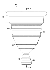
FIGURE 6A illustrates a side view of an example vaginal insert device 40, in
accordance with embodiments of the present disclosure. The vaginal insert
device 40 of
FIGURE 6A comprises an upper portion 42 and a lower, stem-like, removal
portion 44.
As further illustrated and described in more detail below, the upper portion
42 includes a
rim 46 as well as ridges 48 which are preferably spaced apart from the top of
the upper
portion to the lower end of the upper portion. Ridges 48 can be randomly or
uniformly
spaced. The removal portion can also have ridges 48, which like the upper
portion are
spaced apart from the top of the removal portion to the lower end of the
removal portion.
FIGURE 6B illustrates a side view of another example vaginal insert device 40,
in
accordance with embodiments of the present disclosure. In this embodiment,
device 40 is
the same as the embodiment shown in FIGURE 6A except the removal portion 44 is
a
string, cord or ribbon (collectively referred to as "a string"), such as is
used in removing a
tampon.
FIGURE 7 illustrates a perspective view of the vaginal insert device 40 of
FIGURE 6A. As shown in FIGURE 7, the upper portion 42 has a cone-shaped body,
having a circular transverse cross-section throughout its length, has a wall
49 with an
CA 02996163 2018-02-20
WO 2017/031456
PCT/US2016/047859
7
interior side 50 and an exterior side 52, an upper open end 54, a lower end
56, and a
hollow interior 58, wherein the circumference of the upper portion decreases
from the
upper open end to the lower end. As illustrated, rim 46 is preferably circular
and
surrounds and protrudes from the exterior side 52 of the wall and is adjacent
to the upper
open end 54. Ridges 48 are preferably circular rings which surround the
exterior side 52
of wall 49. As further illustrated, a stem or removal portion 44 extends from
the lower
end 56 of the upper portion 42. The upper portion 42 and the stem 44 can be
fabricated as
an integral one-piece device. FIGURE 7 also illustrates that the stem 44 can
have a cone-
shaped body.
FIGURE 8 is a cross-sectional view of vaginal insert device 40 of FIGURE 6A
across section line A-A. As shown in FIGURE 8, stem 44 can have a circular
transverse
cross-section throughout its length, having a wall 60, an upper end 62, a
lower open end
64, and a hollow interior 66, wherein the circumference of the stem increases
from the
upper end to the lower open end. As illustrated, ridges 48 protrude from the
exterior side
52 of the wall 49.
FIGURE 8 further illustrates an embodiment of vaginal insert device 40 which
includes a ventilation opening 68. The ventilation opening can include a
ventilation hole,
a screen or a mesh or any other component with an opening. As would be
understand by
one of ordinary skill of the art, vaginal insert device 40 can include a
plurality of
ventilation openings in locations other than, or in addition to, ventilation
opening 68, such
as in wall 49 of the upper portion 42. The one or more ventilation openings
are intended
to make the vaginal insert device more comfortable for the patient when
inserted. The
one or more openings may also equalize the air pressure between the inside and
outside of
the vagina 18, when vaginal insert device 40 is inserted. However, having a
ventilation
opening is not required for the vaginal insert device to be comfortable,
useful and
effective.
FIGURE 8 illustrates further detail regarding an embodiment where rim 46 has a
first section 70 and a second section 72, both of which protrude from the
exterior side 52
of the wall 49, with the first section protruding a greater distance than the
second section.
A person of ordinary skill in the art would understand that multiple
alternative
embodiments of rim 46 are possible, including an embodiment in which rim 46
comprises
just the first section 70, or another embodiment in which rim 46 comprises
only one
section but has a greater height than first section 70 and protrudes from the
exterior side
CA 02996163 2018-02-20
WO 2017/031456
PCT/US2016/047859
8
52 of the wall the same distance from the top of the rim to the bottom of the
rim. In
another embodiment, rim 46 surrounds the exterior side 52 of the wall 49,
adjacent to the
upper open end 54, and comprises sections which protrude and sections which do
not
protrude from the exterior side of the wall.
With reference to FIGURES 7 and 8, the term "ridges" is intended to be broadly
defined. Accordingly, ridges 48 can include the embodiment illustrated in
FIGURES 7
and 8, in which ridges 48 are protrusions which are preferably circular rings
which
surround the exterior side of wall 49. However, "ridges" can also include any
protrusions
that extend from the exterior side 52 of wall 49, such as a plurality of studs
or knobs.
A person of ordinary skill in the art would understand that the vaginal insert
device 40 can come in different sizes, including different sizes to
accommodate adult
women with differing anatomy. Furthermore, a person of ordinary skill in the
art would
understand that the dimensions of the various sections and portions of the
device 40 can
be modified from the multiple embodiments illustrated and disclosed herein.
For
.. example, referring to Figure 8, the total height 74 of device 40, diameter
76 at the upper
open end 54 of the upper portion 42, and thickness of the wall 49 of the upper
portion 42
of the device 40 can be modified, while retaining or improving on the intended
usefulness, effectiveness and other benefits of the device. The following non-
exclusive
list of dimensions, in reference to FIGURE 8, are non-limiting examples of
embodiments
of device 40 which are believed to be suitable for most women, and which
provide the
intended usefulness, effectiveness and other benefits of the device. For
example, a
suitable total height of device 40 is estimated to be in the range of about
58.0 to 67.0
millimeters (mm), and a suitable outer diameter 76 is estimated to be in the
range of about
38.0 to 44.0 mm. A suitable height of the stem 44 is estimated to be in about
the 13.0 to
15.0 mm range. A suitable thickness of the wall 49, in sections without ridges
48, of the
upper portion 42, below rim 46, is estimated to be about 2.0 mm, whereas a
suitable
thickness of the wall 49, in sections with ridges is estimated to be about 2.5
mm. Wall 60
of stem 44 is estimated to have a suitable thickness of about 1.25 mm in
sections without
ridges 48. A suitable height of rim 46 is estimated to be about 15.0 mm, with
a suitable
.. height of first section 70 estimated to be about 5.0 mm and a suitable
height of second
section 72 estimated to be about 10.0 mm. A suitable thickness of the first
section 70 is
estimated to be about 6.0 mm and the second section 72 is estimated to be
about 4.0 mm.
CA 02996163 2018-02-20
WO 2017/031456
PCT/US2016/047859
9
A suitable outer diameter 82 of lower open end 64 is estimated to be about
10.5 mm. A
suitable diameter of ventilation opening 68 is estimated to be about 2.0 mm.
FIGURE 9 is a bottom view of the vaginal insert device 40 of FIGURE 6A for an
embodiment having ventilation opening 68. FIGURE 10 is a top view of the
vaginal
insert device 40 of FIGURE 6A for an embodiment having ventilation opening 68.
FIGURE 11 is a cross-section of the pelvic region of a female illustrating an
embodiment of the vaginal insert device 40 inserted in the vagina 18 and
applying
pressure on the urethral sphincter 16 to manage, improve, or eliminate female
urinary
incontinence. FIGURES 12 and 13 are each a cross-section of the pelvic region
of a
female illustrating an embodiment of the vaginal insert device 40 inserted in
the vagina
18 to manage, improve, or eliminate POP, in addition to applying pressure on
the urethral
sphincter 16 to manage, improve, or eliminate female urinary incontinence. In
particular,
in FIGURE 12, vaginal insert device 40 is inserted in the vagina 18 to manage,
improve,
or eliminate a prolapsed bladder 26. In particular, in FIGURE 13, vaginal
insert device
40 is inserted in the vagina 18 to manage, improve, or eliminate a prolapsed
uterus 30.
As illustrated in FIGURES 11-13, the upper open end 54 of the upper portion 42
is the
innermost portion of the vaginal insert device 40 during insertion. As further
illustrated
in FIGURES 11-13, the removal portion or stem 44 of an embodiment of vaginal
insert
device 40 can be accessed from the exterior of the vagina 18 when the vaginal
insert
device is inserted and assists in removal of the vaginal insert device. Ridges
48 on stem
44 provide better grip for removal of the device 40 by a patient.
FIGURES 14A and 14B illustrate a method for comfortably inserting vaginal
insert device 40 into vagina 18. As illustrated in FIGURE 14A, a patient can
manually
squeeze the wall 49 of the upper portion to make the upper portion more
compact for
easier insertion of the vaginal insert device 40. As illustrated in FIGURE
14B, once
vaginal insert device 40 is manually inserted into vagina 18, wall 49 expands
back to its
original shape.
FIGURE 15A illustrates a side-view of a pessary applicator 84 which can be
used
to assist in inserting a vaginal insert device 40 into a patient's vagina 18.
Pessary
applicator 84 comprises an insertion member 86, a top portion 90 of the
insertion
member, and a plunger 88. Pessary applicator 84 is generally similar to a
tampon
applicator. However, the insertion member 86 will generally have a greater
circumference than a tampon applicator to accommodate a vaginal insert device
40,
CA 02996163 2018-02-20
WO 2017/031456
PCT/US2016/047859
which when compacted has a shape which is generally larger than the
circumference of a
tampon. FIGURES 15B-15C illustrate a cross-section of the pessary applicator
84 of
FIGURE 15A, and a method of using the applicator to comfortably insert a
vaginal insert
device 40 into a patient's vagina 18. As is illustrated, vagina insert device
40 is housed
5 inside insertion member 86 in a compacted shape. Similar to the process
of insertion of a
tampon into a vagina using an applicator, insertion member 86 of applicator 84
is inserted
into the patient's vagina 18, and the plunger 88 is pushed towards the
insertion member,
ejecting the vaginal insert device 40 through the top portion 90. The
applicator 84 is then
removed from the vagina 18, and the vaginal insert device 40 remains in place
in the
10 vagina, expanded back to its normal shape. The vaginal insert device 40
which has been
inserted is positioned such as is illustrated in FIGURE 11.
This disclosure encompasses all changes, substitutions, variations,
alterations, and
modifications to the example embodiments herein that a person having ordinary
skill in
the art would comprehend. Similarly, where appropriate, the appended claims
encompass
all changes, substitutions, variations, alterations, and modifications to the
example
embodiments herein that a person having ordinary skill in the art would
comprehend.
Moreover, reference in the appended claims to an apparatus, device or system
or a
component, section, or portion of an apparatus, device or system being adapted
to,
arranged to, capable of, configured to, enabled to, operable to, or operative
to perform a
particular function encompasses that apparatus, device, system, or component,
whether or
not it or that particular function is used, activated, turned on, or unlocked,
as long as that
apparatus, system, device or component is so adapted, arranged, capable,
configured,
enabled, operable, or operative.
All examples and conditional language recited herein are intended for
pedagogical
objects to aid the reader in understanding the disclosure and the concepts
contributed by
the inventor to furthering the art, and are construed as being without
limitation to such
specifically recited examples and conditions. Although embodiments of the
present
disclosure have been described in detail, it should be understood that various
changes,
substitutions, and alterations could be made hereto without departing from the
spirit and
scope of the disclosure.