Note: Descriptions are shown in the official language in which they were submitted.
1
IMAGE PROCESSING SYSTEM FOR INSPECTING OBJECT DISTANCE AND
DIMENSIONS USING A HAND-HELD CAMERA WITH A COLLIMATED LASER.
The present invention related to the application of image processing
techniques to inspect object dimensions using a hand-held camera with a
collimated
laser. More specifically, the application of image processing techniques for
the
detection of a laser blob in a sequence of images in order to infer object
distance and
dimensions.
BACKGROUND OF THE INVENTION.
As hand-held cameras become ubiquitous, it is desirable to extend their
capabilities beyond the basic image acquisition. Camera-based optical
triangulation is
a cost effective method for optical sensing techniques that can be used to
measure
distances to objects, and related parameters such as displacements and surface
dimensions. Compared to other standalone range finders, camera-based optical
triangulation requires minimum hardware addition to existing designs, thus
making it
an attractive alternative.
The general application of such systems is as follows:
-1- The camera optics is laterally displaced from the laser source by
a predetermined distance;
-2- The collimated laser source is used to project a laser blob on the
object at distance to be determined;
-3- A laser detection method is used to detect the center of the laser
blob in terms of exact sensor pixels coordinates;
CA 2996173 2019-10-17
2
-4- Preliminary camera calibration is used to determine the angle
associated with the detected pixel coordinates;
-5- The distance to be determined is determined from D = H
an (9).
For most cases, the preliminary camera calibration and steps 1, 2, and
4 are basically the same. The fundamental difference between individual
systems are
in stage 3 in relation to the detection of the blob on the pixels as set out
hereinafter.
The basic requirement of a camera-based optical triangulation system
is the ability to detect the laser blob location in the captured image
sequence. The two
most common approaches for laser blob detection are based on finding local
extrema
and background differencing.
In the local extrema method, most blob detection methods in general,
and laser blob detection methods in particular, are based on finding local
extrema
within the image domain. Local extrema detectors usually require image
manipulation
prior to the extrema search. Moreover, the extrema search for the laser blob
detector
is often reduced to maximum pixel intensity search in the image domain.
A number of problems arise. Firstly in relation to high intensity
background objects, the basic requirement of the disclosed image processing
system
is the ability to detect the laser projection emitted from the integrated
laser source.
Additionally, a fundamental characteristic of the laser projection emitted
from the
integrated laser source is that the resulting laser blob in the image domain
can take
various forms in terms of size, intensity, and color due to ambient light
conditions and
the target distance, color, brightness, and texture.
CA 2996173 2019-10-17
3
Extrema-based techniques usually cannot distinguish between a laser
blob that was originated from the integrated laser source and other bright
blobs
captured in the processed image.
Further problems can arise in view of non-homogeneous targets.
Another fundamental characteristic of the disclosed image processing system is
that
target objects might have non-homogeneous color, intensity, and texture.
Hence, the
resulting laser blob in the image domain might also have non-homogeneous form
it
terms of color, intensity and shape. Extrema-based detectors have a
significant
difficulty in handling such discontinuities in laser blobs of different sizes.
Yet another requirement of the disclosed image processing system is
ability to provide a perceived real-time user feedback. Many of the existing
extrema-
based image processing approaches for blob detection are computationally
intensive
and are not suitable for embedded application such as a hand-held camera
device.
When appropriate, laser blob detectors can also use a background
differencing approach. In this case the background image does not include the
laser
projection while the foreground image does. The laser blob is detected by
computing
the difference between every pixel in the background image from the
corresponding
pixel in the foreground image. High intensity pixels in the resulting
difference image
are detected as the laser blob.
Problems arise in relation to the background differencing approach firstly
in relation to high intensity targets where laser blob detectors that rely on
conventional
background differencing often fail to properly detect laser projections on
high intensity
CA 2996173 2019-10-17
4
targets. This is due to the non-homogeneous difference image resulting from
the
background subtraction. In this case different regions of the laser blob have
significant
intensity differences thus not detected as a laser blob.
Furthermore, variation in ambient light provide another common
problem associated with background differencing techniques caused by their
high
sensitivity to changes in ambient light. Therefore, laser blob detectors based
on
conventional background differencing are usually used in well controlled
environments
which is not necessarily the case for hand-held devices.
Yet another problem with the background differencing method, arising
from a non-homogeneous background, is that it requires the laser projection to
be the
only difference between the background image and the foreground image. Since
there
is a time difference between the acquisitions of the background and the
foreground
images, factors such as hand shaking, object vibration, and other scenery
updates
can easily result in false laser detections.
SUMMARY OF THE INVENTION.
It is an object of the present invention to provide an improved digital
image processing method for measuring object distance and dimensions using a
hand-held camera with a collimated laser.
According to a first aspect of the present invention there is provided a
method for optically determining the distance to and object using a hand held
camera,
the method comprising the steps of:
CA 2996173 2019-10-17
5
acquiring using camera optics two sequential images of the target object
wherein one of the images is a background image and the other of the images is
a
foreground image;
illuminating the target object in the foreground image with a collimated
laser source that is laterally displaced from the camera optics to form a
laser blob on
the foreground image;
where the target object in the background image is not illuminated with
the collimated laser source;
analyzing the background and foreground images in order to extract the
laser blob coordinates in the image domain;
and calculating the distance to the object from the blob coordinates;
wherein said analyzing uses a background differencing step which
generates a difference image between the background and foreground images;
and wherein in said analyzing both the foreground and background
images are filtered using a convolved filter based on a scale independent
version of
the Bartlett window.
Thus both the foreground and background images are filtered using a
convolved filter based on a scale independent version of the Bartlett window
in order
to reduce interference caused by non-homogenous backgrounds and non-
homogenous targets.
Preferably the Bartlett window is implemented by convolving a box filter
of size K/2 with itself which in turn is implemented as separate convolution
of two 1-
CA 2996173 2019-10-17
6
dimensional moving average filters resulting in an 0 (M x N) processing time
where
M and N represent the image size..
According to a second aspect of the invention there is provided a method
for optically determining the distance to and object using a hand held camera,
the
method comprising the steps of:
acquiring using camera optics two sequential images of the target object
wherein one of the images is a background image and the other of the images is
a
foreground image;
illuminating the target object in the foreground image with a collimated
laser source that is laterally displaced from the camera optics to form a
laser blob on
the foreground image;
where the target object in the background image is not illuminated with
the collimated laser source;
analyzing the background and foreground images in order to extract the
laser blob coordinates in the image domain;
and calculating the distance to the object from the blob coordinates;
wherein said analyzing uses a background differencing step which
generates a difference image between the background and foreground images;
and wherein said analyzing uses a step in which the intensity of one
color channel in the foreground image is enhanced relative to other color
channels
where the enhanced color channel corresponds to a dominant color of the
collimated
laser source.
CA 2996173 2019-10-17
7
According to a third aspect of the invention there is provided a method
for optically determining the distance to and object using a hand held camera,
the
method comprising the steps of:
acquiring using camera optics two sequential images of the target object
wherein one of the images is a background image and the other of the images is
a
foreground image;
illuminating the target object in the foreground image with a collimated
laser source that is laterally displaced from the camera optics to form a
laser blob on
the foreground image;
where the target object in the background image is not illuminated with
the collimated laser source;
analyzing the background and foreground images in order to extract the
laser blob coordinates in the image domain;
and calculating the distance to the object from the blob coordinates;
wherein said analyzing uses a background differencing step which
generates a difference image between the background and foreground images;
wherein the analysing includes a dynamic thresholding step using
incremented threshold levels to produce a list of potential laser blobs.
According to a fourth aspect of the invention there is provided a method
for optically determining the distance to and object using a hand held camera,
the
method comprising the steps of:
CA 2996173 2019-10-17
8
acquiring using camera optics two sequential images of the target object
wherein one of the images is a background image and the other of the images is
a
foreground image;
illuminating the target object in the foreground image with a collimated
laser source that is laterally displaced from the camera optics to form a
laser blob on
the foreground image;
where the target object in the background image is not illuminated with
the collimated laser source;
analyzing the background and foreground images in order to extract the
laser blob coordinates in the image domain;
and calculating the distance to the object from the blob coordinates;
wherein said analyzing uses a background differencing step which
generates a difference image between the background and foreground images;
wherein the analysing includes producing a list of potential laser blobs;
and wherein a voting function is used to analyze the potential laser blobs
based on at least one of their size, aspect ratio, and the original color in
the foreground
image, where the potential laser blob with the highest vote is selected and
its center
of mass is used to determine the distance from the camera to the illuminated
object.
Preferably, before the background differencing step, the intensity of one
color channel in the foreground image is enhanced relative to other color
channels
where the enhanced color channel corresponds to a dominant color of the
collimated
CA 2996173 2019-10-17
9
laser source in order to reduce interference caused by non-homogenous
backgrounds
and non-homogenous targets.
Preferably a directional histogram spread is applied to the difference
image produced by the background differencing step in order to reduce
interference
caused by non-homogenous backgrounds and non-homogenous targets.
Preferably, in the histogram spread, individual pixels are enhanced in a
manner that results with a top histogram bin having enough pixels to represent
the
smallest allowable laser blob.
Preferably the difference image produced by the background
differencing step is used in a dynamic thresholding step using incremented
threshold
levels to produce a list of potential laser blobs in order to facilitate blob
detection for
different size laser blobs, various ambient light condition, and high
intensity targets.
Preferably the dynamic thresholding step uses sub-thresholds of at least
one of pixel intensity, cluster size, cluster diameter, and cluster aspect
ratio which are
progressively adjusted to fit laser blobs that fall between the following two
laser blob
types:
Type A are laser blobs that correspond to one or more of the following:
Close target object.
Dark ambient light condition.
High intensity target object.
Type B are laser blobs that correspond to one or more of the following:
CA 2996173 2019-10-17
10
Far target object.
Bright ambient light condition.
Low intensity object.
Preferably a voting function is used to analyze the potential laser blobs
based on at least one of their size, aspect ratio, and the original color in
the foreground
image, where the potential laser blob with the highest vote is selected and
its center
of mass is used to determine the distance from the camera to the illuminated
object.
Preferably the voting function used is:
V = aS ¨ bA + cCG
Where:
a is the weight coefficient for the size of the laser blob.
S is the size of the laser blob in pixel count.
b is the weight coefficient for the aspect ratio.
A is the aspect ratio of the laser blob.
c is the weight coefficient for the overall color of the laser blob.
CG is the color grade computed for the laser blob.
CA 2996173 2019-10-17
11
The method can also include the step of calibrating the hand-held device
and determining region of interest (ROI) for laser blob detection.
The method can also include the step of using the distance between the
hand-held device and the illuminated object to infer other related parameters
such as
displacements and surface dimensions in known manner.
In particular, the inventive aspects employ various image processing
techniques for laser blob detection using the input images. The proposed blob
detection can be divided into two smaller steps comprising of image pre-
processing
and blob extraction.
The goal of image pre-processing is to accentuate the laser blob
features in the image domain thus making it easier to extract the laser blob
coordinates. In general, the inventive aspects of the pre-processing step
focus on
improving the image differencing approach. The input to the pre-processing
step are
two images captured by the hand-held camera. One of the images is identified
as a
background image and it does not include the laser projection while the other
image
is identified as a foreground image that includes the laser projection. That
is these
images are taken sequentially in no particular order and the only difference
is that one
is illuminated with the laser which is activated at the required time and the
other does
not contain the laser beam which is turned off. The laser beam is directed at
the main
object of the image to be taken.
The output of this background differencing step is a single difference
image that has been pre-processed to facilitate more accurate blob detection.
CA 2996173 2019-10-17
12
The pre-processing steps include image filtering, image enhancement,
image-differencing, and histogram spread.
The input images are first filtered with a Bartlett window in order to
eliminate the differences between the background and foreground images that
are
due to relative motion between the hand-held device and the non-homogeneous
background. Additionally, the filter using the Bartlett window homogenizes the
laser
blob core in the foreground image while preserving the round characteristics
of the
laser blob thus reducing the effect of non-homogeneous targets. Yet another
important
advantage of this filter is it the ability to optimize its implementation to
be scale
independent, thus requiring much less computational resource.
After the filter using the Bartlett window is applied to both input images,
errors due to motion are further addressed by enhancing the intensity of one
of the
color channels in the foreground image. The two resulting images are then
differentiated and their histogram is computed.
The final step of the pre-processing is a directional histogram spread
that allows for a more accurate laser blob detection.
Next, the resultant difference image and the original foreground image
are fed into the blob detection step. The blob detection process employs a
dynamic
thresholding technique where the process iterates through the difference image
with
incremented threshold levels until at least one potential laser blob is
detected or the
maximum threshold level has been reached.
CA 2996173 2019-10-17
13
The dynamic thresholding step produces a set of potential laser blobs
that are fed into a blob voting stage. The vote function consists of the blob
size, aspect
ratio and the original color in the foreground image. The blob with the
highest vote is
selected as the laser blob produced by the integrated laser source and its
center of
mass is used to determine the distance from the camera to the illuminated
object.
The same invention can be expressed as a hand held camera arranged
for optically determining the distance to an object using, the camera
comprising:
camera optics arranged to acquire two sequential images of the target
object wherein one of the images is a background image and the other of the
images
is a foreground image;
a collimated laser source arranged for illuminating the target object in
the foreground image with that is laterally displaced from the camera optics
to form a
laser blob on the foreground image, where the target object in the background
image
is not illuminated with the collimated laser source;
a processing system for analyzing the background and foreground
images in order to extract the laser blob coordinates in the image domain;
the processing system being arranged for calculating the distance to the
object from the blob coordinates;
the processing system being arranged to provide a background
differencing step which generates a difference image between the background
and
foreground images;
where
CA 2996173 2019-10-17
14
the processing system includes a filter arranged in said analyzing both
the foreground and background images using a convolved filter based on a scale
independent version of the Bartlett window.
Or
wherein the processing system includes an arrangement for producing
a list of potential laser blobs and a voting function is used to analyze the
potential laser
blobs based on at least one of their size, aspect ratio, and the original
color in the
foreground image, where the potential laser blob with the highest vote is
selected and
its center of mass is used to determine the distance from the camera to the
illuminated
object.
Or
the processing system includes an arrangement providing a dynamic
thresholding step using incremented threshold levels to produce a list of
potential laser
blobs.
Or
the processing system includes an arrangement providing a step in
which the intensity of one color channel in the foreground image is enhanced
relative
to other color channels where the enhanced color channel corresponds to a
dominant
color of the collimated laser source.
CA 2996173 2019-10-17
15
BRIEF DESCRIPTION OF THE DRAWINGS.
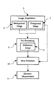
Figure 1 shows the principles of camera-based optical triangulation.
Figure 2 is a flow chart for the overall image processing method for laser
blob detection.
Figure 3 is a flow chart for the pre-processing step of Figure 2.
Figure 4 is a flow chart for the blob detection step of Figure 2.
Figure 5 is a flow chart for the dynamic thresholding stage of the blob
detection step of Figure 4.
DETAILED DESCRIPTION OF THE INVENTION
The following detailed description is divided into three sections. The first
section will address the overall image processing flow of the invention. Next,
the pre-
processing step of the invention will be described in details. The last
section will
elaborate on the blob extraction process of the invention.
Figure 2 shows the overall image flow for the image processing method
for laser blob detection.
A previously calibrated hand-held camera device captures at step 5 two
sequential images of the target object 3 from Figure 1. The time between the
first and
the second image acquisitions is usually under a second and the images are
referred
to as a background image 6 and a foreground image 7. The target object in the
foreground image 7 is illuminated with a collimated laser source that is
laterally
displaced from the camera optics as shown in Figure 1. The target object in
the
background image 6 is not illuminated by the laser source.
CA 2996173 2019-10-17
16
Both images are then fed into the pre-processing step 8 which employs
several image processing techniques as shown in Figure 3 in order to
facilitate correct
laser blob detection in various environments.
Next, a single pre-processed difference image 9 of the two original
images is fed into the blob detection step along with the original foreground
image 7.
The blob detection step 10 uses dynamic thresholding and a voting mechanism in
order to extract the laser blob coordinates in the image domain. Finally, the
extracted
coordinates of the laser projection are used in the distance measurement step
11
described above in relation to Figure 1 in order to measure the distance to
the
captured object and other related parameters. Once the distance measurement
step
ills complete the process can start over at the image acquisition stage 5.
The image pre-processing step accentuates the laser blob features in
the image domain and attenuates other background interferences in order to
facilitate
a more accurate laser blob detection. As shown in Figure 3. the pre-processing
step
8 includes four stages: image filtering 13, foreground enhancement 14,
background
differencing 15, and histogram spread 17.
The initial pre-processing stage 13 is to filter both input images in order
to reduce undesired effects when the laser blob detection is performed in a
non-
homogeneous background or on a non-homogeneous target.
Acquiring input images in a non-homogeneous background will usually
result in high frequency images. Likewise, scenery updates that accrued
between the
acquisition of the first and second input images will often result in high
frequency
CA 2996173 2019-10-17
17
differences between the two images. Such high frequency differences will
interfere
with, and in many cases prevent, accurate laser blob detection. The most
common
cause for high frequency differences between the two input images is relative
motion
between the hand-held camera and the target object in a non-homogeneous
background, more specifically, motion due to shaky hands of the camera
operator. In
order to attenuate the high frequency differences due to motion, the input
images are
passed through a Bartlett (triangular) window of size K x K, where K depends
on the
image resolution and it is set to be about the size of pixel diameter of the
smallest
laser blob the system is designed to detect.
The Bartlett window is implemented by convolving a box filter of size K/2
with itself which in turn is implemented as separate convolution of two 1-
dimensional
moving average filters resulting in an 0 (M x N) processing time where M and N
represent the image size. Therefore, the image filtering process does not
depend on
the scale of the filter thus requiring significantly less computational
resources.
The averaging characteristic of the Bartlett window used in the filtering
stage 13 also corrects for errors due to non-homogeneous targets. The
resulting laser
projection on a non-homogeneous targets will also have non-homogeneous
characteristics in terms of color, intensity, and texture. More specifically,
the laser
projection portion that falls onto the high intensity area of the target
object will result
in low intensity differences while the laser projection that falls onto the
low intensity
area of the target object will result in high intensity differences. This
situation
CA 2996173 2019-10-17
18
introduces an error when determining the exact center of the laser blob and
the
averaging characteristics of the Bartlett windows will minimize this error.
The second pre-processing stage 14 is the foreground enhancement
which further reduces undesired effects when the laser blob detection is
performed in
a non-homogeneous background or on a non-homogeneous target.
In the foreground enhancement stage 14, one of the color channels in
the foreground image is enhanced. The enhanced color channel in selected based
on
the dominant color of the laser source, that is, if the dominant laser source
is red, then
the red channel in the foreground image is enhanced. Enhancing the color
channel
that correspond to the laser's dominant color will have minimal effect on
other high
intensity blobs in the foreground image due to pixel saturation, however, it
will
significantly increase the intensity difference caused by the laser
projection.
Additionally, due to pixel saturation, the foreground enhancement will
homogenize the
core of the laser blob which in turn allow for more accurate detection of the
center of
the laser blob.
In the third stage 15 of the pre-processing step of the invention, the
manipulated background and foreground images are used to generate a difference
image 16 where each pixel in the difference image represents the intensity
difference
between the corresponding pixels in the background and foreground images. The
pixel intensity in the resulting difference image represents intensity
difference between
the background and foreground image and therefore the background differencing
stage acts to filter out any static high intensity areas around the target
object.
CA 2996173 2019-10-17
19
During the image differencing stage 15, the histogram of the difference
image 16 is also computed as a preparation to the histogram spread performed
in the
following pre-processing stage.
In the fourth stage 17 of the pre-processing step of the invention, a one
direction histogram spread is applied to the difference image 16 in order to
allow for
more accurate laser blob detection in different ambient light conditions. The
histogram
spread is performed in a manner that results with the top histogram bin having
enough
pixels to represent the smallest allowable laser blob. In darker ambient light
the laser
projection will cause significant intensity differences in the difference
image and
therefore the histogram spread will have minimal effect. On the other hand, in
bright
ambient light condition, the laser projection will cause minimal intensity
differences in
the difference image and the histogram spread will spread these differences
and allow
better blob detection.
The second step of the invention shown in Figures 4 and 5 is a laser
blob detection method that uses dynamic thresholding and voting mechanism in
order
to extract the image domain coordinate of the laser blob that originated form
the
integrated collimated laser source. As shown in Figure 4, the laser blob
detection 10
starts with dynamic thresholding 19 that is used to detect all potential laser
blobs in
the difference image. In decision 20, if no potential laser blob are detected
the process
exits 21 and the distance measurement is not performed for the current image
sequence. Otherwise, the process continues to the blob voting stage 22 where
the
CA 2996173 2019-10-17
20
best blob is selected and its center of mass is used to determine the distance
from the
camera to the illuminated object..
In the dynamic thresholding stage, the difference image produced by the
image differencing and histogram spread is used in a dynamic thresholding step
with
incremented threshold levels. The levels are incremented until a satisfactory
blob is
detected or until the maximum threshold level has been reached. Each threshold
level
is associated with the following sub-thresholds:
-1- Minimum pixel intensity.
-2- Minimum and maximum blob size.
-3- Minimum and maximum blob diameter.
-4- Minimum and maximum blob aspect ratio.
The sub-thresholds are progressively adjusted to suit laser blobs that
fall between the following laser blob types:
-A- Type A laser blobs are laser blob projections that are
produced
when one or more of the following are true:
-1- Close target object.
-2- Dark ambient light condition.
-3- High intensity target object.
Type A laser blob projections are characterised by:
-1- High pixel intensity in the difference image.
-2- Large laser blob size.
-3- Large laser blob diameter.
CA 2996173 2019-10-17
21
-4- High variance from a perfect circle.
-B- Type B laser blobs are laser blob projections that are
produced
when one or more of the following are true:
-1- Far target object.
-2- Bright ambient light condition.
-3- Low intensity object.
Type B laser blob projections are characterised by:
-1- Low pixel intensity in the difference image.
-2- Small laser blob size.
-3- Small laser blob diameter. '
-4- Low variance from a perfect circle.
Figure 5 shows a detailed flow chart of the dynamic thresholding process
19. The process starts with setting, at step 24, the initial threshold level
that is used
for the thresholding. The initial threshold level is set to the lowest level
that includes
sub-thresholds that correspond to laser blobs of type A. Each incremented
threshold
level includes sub-thresholds that are more suitable for laser blobs of type
B.
In decision 25, if the maximum threshold level has been reached and
the dynamic thresholding process exits with no potential laser blobs.
Otherwise the
process continues to apply the sub-threshold that corresponds to the current
threshold
level. The first sub-threshold that is applied is the intensity threshold 26.
The intensity
threshold produces a binary image where clusters of "ones" in the resulting
binary
image represent potential laser blobs. In decision 27, if the count of "ones"
in the
CA 2996173 2019-10-17
22
resulting binary image is less than the smallest allowable laser blob size the
thresholding of the difference image is repeated again with an incremented
threshold
level 24. Once the binary image includes enough "ones" to represent the
smallest
allowable laser blob the binary image is scanned to detect all clusters of
"ones" that
represent potential laser blobs 28. A further thresholding of each potential
laser blob
is then carried out in stage 29 based on its size, diameter, and aspect ratio.
In decision
30, if none of the potential blobs passes the blob thresholding stage 29, the
thresholding process starts over with an incremented threshold level 24.
Otherwise,
the process continues to the bob voting stage.
The blob voting stage starts with computing the color grade (CO) for all
potential laser blobs. The color grade represents the correlation between the
potential
laser blob color in the original foreground image and the dominant color of
the
integrated collimated laser source. For example, if the dominant color of the
laser
source is red, potential laser blobs that appear red in the original
foreground image
will receive a higher CG than potential laser blobs that are less red. Once
the CGs are
assigned, each potential laser blob is given a vote based on:
V = aS ¨ bA + cCG
Where:
a is the weight coefficient for the size of the laser blob.
S is the size of the laser blob in pixel count.
b is the weight coefficient for the aspect ratio.
A is the aspect ratio of the laser blob.
CA 2996173 2019-10-17
23
c is the weight coefficient for the overall color of the laser blob.
CG is the color grade computed for the laser blob.
The blob with the highest vote is selected as the laser blob produced by
the integrated laser source and its center of mass is used to determine the
distance
from the camera to the illuminated object.
CA 2996173 2019-10-17