Note: Descriptions are shown in the official language in which they were submitted.
84184687
1
System and method for milking a group of milking animals
The invention relates to a system and a method for milking a group of milking
animals, in particular cows.
WO 2014/055002 Al discloses an automatic milking system in which milking
animals can walk freely around an accommodation space with feeding stations.
The milking
animals visit the feeding stations voluntarily. Each feeding station comprises
a feed trough and a
feed metering device for dispensing a specific quantity of feed such as
concentrate. In front of
each feed trough is a neck lock device for locking at the neck an animal which
has pushed its
head above or into the feed trough of a feeding station. Some of the feeding
stations are
configured as milking stations, i.e. an animal can be milked in these feeding
stations. When an
animal approaches such a feed/milking station, the animal is first identified
and it is established
whether the animal is ready for milking. If so, the animal is secured by the
neck lock device and
then milked. In practice, it has been found that an animal becomes restless
and moves around
when said animal is locked at the neck by such a neck lock device, which
hinders the connection
of the milking cups to the teats of said animal.
One object of the invention is to provide an improved system for milking a
group
of milking animals, in particular cows, wherein in particular the automatic
connection of the milking
cups can be carried out rapidly and reliably while the milking animals are
locked at the neck in
the milking stations.
This object is achieved according to the invention by a system for milking a
group
of milking animals, in particular cows, wherein the system comprises:
- an accommodation space for the milking animals, which is preferably
stationary and/or
comprises a fixed floor and/or is fenced off,
- a plurality of milking stations, preferably stationary milking stations,
which are each
arranged or placed at a fixed location and next to each other, wherein the
milking stations
each comprise an entry opening for entry of a milking animal from the
accommodation
space to said milking station, and wherein each milking station at a head end
thereof,
preferably situated opposite the entry opening of said milking station,
comprises a neck
lock device which comprises an actuator device and can be actuated and/or
moved by
means of said actuator device between a locked state in which the milking
animal in said
milking station can be locked at the neck by the neck lock device, in
particular in order to
secure and/or hold said milking animal in said milking station, and an open
state in which
Date Recue/Date Received 2022-09-14
84184687
2
the milking animal present in said milking station is free to move its head in
and/or out of
said neck lock device, and preferably is free to leave said milking station,
- a control system which is actively connected to the actuator device of each
neck lock
device, wherein the control system is configured to control the actuator
devices, and
- an
automatic milking system for the automatic milking of milking animals present
in the
milking stations, wherein in particular the milking system comprises milking
cups and is
configured to automatically connect milking cups to the teats of the milking
animal,
wherein the milking system is configured to milk the milking animal which is
locked at the
neck in a milking station by means of the neck lock device of said milking
station and is
preferably secured and/or held thereby on the condition that said milking
animal fulfils a
predefined milking criterion, in particular after the milking cups have been
connected
automatically to the teats of said milking animal by means of the milking
system,
wherein the control system is configured and/or programmed to determine and/or
detect, for each
milking station, whether the milking animal in said milking station has a
position and/or attitude
which is suitable for locking said milking animal at the neck by the neck lock
device of said milking
station, and to control the actuator devices such that each milking animal
which enters one of the
milking stations and then assumes the position and/or attitude which is
suitable for locking said
milking animal at the neck by the neck lock device of said milking station,
irrespective of whether
said milking animal fulfils the milking criterion, is locked at the neck in
said milking station by
movement of the neck lock device of said milking station from the open state
to the locked state.
According to the invention, each milking animal is locked at the neck by the
neck
lock device on each visit to one of the milking stations. The control system
is preferably configured
such that the neck lock device of each milking station which is not occupied
by a milking animal,
is in the open state. As soon as the control system establishes that the
milking animal, on a visit
to a milking station, assumes a position and/or attitude which is suitable for
locking said milking
animal at the neck, in particular the position and/or attitude of the milking
animal for eating and/or
drinking from a feed and/or drinking trough of said milking station, the
milking animal is locked at
the neck so that said milking animal is secured in said milking station. Not
only milking animals
which fulfil the milking criterion, i.e. are ready for milking and must be
milked, but also milking
animals which do not fulfil the milking criterion, i.e. are not ready for
milking and need not be
milked, are locked at the neck by means of the neck lock device. In
Date Recue/Date Received 2022-09-14
CA 02996264 2018-02-21
3
WO 2017/034394
PCT/NL2016/050535
contrast to the prior art, wherein the milking animals are held at the neck
during some
visits but not during other visits, with the system according to the
invention, the milking
animals are always locked at the neck as soon as the milking animals have the
suitable
position and/or attitude, for example push their heads above or into a feed
and/or
drinking trough. It has been found that the milking animals become used to the
neck
lock if the neck lock is always applied, i.e. also if the milking animal need
not be milked
and therefore there is no real need to secure the milking animal. The milking
animals
thus become conditioned so the milking animals remain calm when the milking
animals
are locked at the neck. If the milking animals are ready for milking, the
milking cups of
the automatic milking system can thus be connected to the teats reliably and
rapidly.
The neck lock also has no harmful effect on the visit behavior of the milking
animals to
the milking stations.
In one embodiment, the milking stations at the head ends thereof
comprise at least one feed and/or drinking trough, wherein the position and/or
attitude of
a milking animal in a milking station which is suitable for locking said
milking animal at
the neck by the neck lock device of said milking station, is formed by the
position and/or
attitude of said milking animal when said milking animal is situated with its
head above
or in the feed and/or drinking trough of said milking station. At each milking
station, the
at least one feed and/or drinking trough is positioned relative to the neck
lock device
such that a milking animal in said milking station must push its head through
the neck
lock device of said milking station, in the open state, in order to eat and/or
drink from the
feed and/or drinking trough. The neck lock device prevents the milking animal
from
being able to withdraw its head from the feed and/or drinking trough. The
control system
is configured to control the actuator devices such that each milking animal
which enters
one of the milking stations and then pushes its head above or into the feed
and/or
drinking trough of said milking station, irrespective of whether said milking
animal fulfils
the milking criterion, is locked at the neck in said milking station by
movement of the
neck lock device of said milking station from the open state to the locked
state.
According to the invention, each milking animal which in one of the milking
stations
pushes its head above or into the feed and/or drinking trough in order to eat
and/or
drink, is locked at the neck by the neck lock device so that said milking
animal is held in
said milking station. Since the milking animals, on visiting a milking
station, almost
always want to eat and/or drink from the feed and/or drinking trough of said
milking
station, it is guaranteed that on almost every visit the milking animals can
be locked at
the neck.
CA 02996264 2018-02-21
4
WO 2017/034394
PCT/NL2016/050535
In one embodiment, each milking station comprises a separate feed
and/or drinking trough, wherein the feed and/or drinking trough of each
milking station is
positioned relative to the neck lock device of said milking station such that
a milking
animal in said milking station must push its head through the neck lock device
of said
milking station, in the open state, in order to eat and/or drink. The feed
and/or water in
the separate feed and/or drinking troughs remains relatively fresh, which is
favorable for
the feeding and/or drinking behavior of the milking animals. It is also
possible that,
instead of separate feed and/or drinking troughs for each milking station, the
milking
stations comprise one or more common feed and/or drinking troughs, i.e. two or
more
milking stations situated next to each other share a common feed and/or
drinking trough
from which milking animals present in said milking stations can eat and/or
drink.
Evidently, the milking stations may comprise only one common feed and/or
drinking
trough for all milking stations situated next to each other.
In one embodiment, the system comprises a supply device for the supply
of feed and/or water to each feed and/or drinking trough, wherein at the feed
and/or
drinking trough of each milking station, the supply device is provided with a
sensor
means for sensing whether a milking animal is positioned with its head above
or in the
feed and/or drinking trough, and wherein the supply device is configured such
that feed
and/or water are supplied to a feed and/or drinking trough only if the
associated sensor
means has sensed that a milking animal is positioned with its head above or in
said
feed and/or drinking trough. A milking animal visits the milking station to
eat and/or
drink. Since feed and/or water are supplied to the feed and/or drinking trough
only after
the milking animal has pushed its head above or into the feed and/or drinking
trough,
the milking animal will push its head above or into the feed and/or drinking
trough. In
this way, the milking animal has the position and/or attitude in which the
milking animal
can be reliably and safely locked at the neck.
The sensor means may be configured in various ways. For example, the
sensor means comprise a respective valve at each feed and/or drinking trough,
wherein
each valve is biased or pretensioned to a closed state in which the supply of
feed and/or
water to the associated feed and/or drinking trough is shut off, and can be
actuated by a
milking animal from the closed state to an open state for the supply of feed
and/or water
to said feed and/or drinking trough. In this case, it is possible that the
sensor means
comprise a respective sensor at each feed and/or drinking trough, wherein each
sensor
is configured to detect whether feed and/or water are supplied to the
associated feed
and/or drinking trough. For example, water is only supplied to a drinking
trough of a
CA 02996264 2018-02-21
WO 2017/034394
PCT/NL2016/050535
milking station when a milking animal operates a flap in said drinking trough
with its
nose, whereby the valve opens. In this case for example, the sensor comprises
a flow
meter in a supply line to the drinking trough. When the flow meter detects
that water is
flowing through the supply line to the drinking trough, this means that a
milking animal
5 has its nose in the drinking trough. In other words, only when the
milking animal has
actuated the valve does the milking animal receive feed and/or drink. While
the milking
animal actuates the valve, the milking animal has the position and/or attitude
in the
milking station which is suitable for locking said milking animal at the neck.
Therefore,
the milking animal can be held reliably and safely.
When separate feed and/or drinking troughs are used, the supply device is
preferably configured to determine and/or detect the respective quantity of
feed and/or
water supplied to each of the feed and/or drinking troughs by the supply
device. The
quantity of feed and/or water supplied to each of the feed and/or drinking
troughs can
be used to derive the quantity of feed and/or water which the milking animals
have
eaten and/or drunk therefrom. Therefore, the feed and/or water consumption,
and the
feeding and/or drinking behavior of the milking animals can be monitored
individually.
In this patent application, the term "water" or "drinking water" means every
type of drink for milking animals. The water is of such a quality that the
water is suitable
for drinking by the milking animals. Possibly, a feed supplement and/or
medication
and/or other additives may be added to the water. In this patent application,
water with
such an additive is also referred to by the term "water" or "drinking water".
In one embodiment, the system comprises an animal identification system
for identifying each milking animal which visits one of the milking stations.
For example,
the animal identification system comprises transponders which are arranged on
each of
the milking animals, for example on a collar around the neck of each milking
animal,
and also readout units for reading the transponders, wherein one of the
readout units is
arranged at each milking station. By means of the animal identification
system, a milking
animal visiting one of the milking stations can be identified. For example, by
means of
the control system it can be established whether said milking animal is ready
for milking,
i.e. whether or not it needs to be milked.
The readout units are preferably arranged at the head end of each milking
station, wherein the control system is actively connected to the readout units
of the
milking stations. The control system is for example configured such that the
neck lock
device of each milking station is moved from the open state to the locked
state on the
condition that the readout unit of said milking station has read a transponder
of one of
CA 02996264 2018-02-21
WO 2017/034394 6
PCT/NL2016/050535
the milking animals and the sensor means has sensed or detected that said
milking
animal has pushed its head above or into the feed and/or drinking trough of
said milking
station.
Although the readout units of the milking stations can identify the milking
animals by means of the transponders, it cannot be accurately established
whether the
milking animals are in the correct position and/or attitude in the milking
station for
locking at the neck. The position and/or attitude which is suitable for
locking at the neck
can be detected by the sensor means for sensing whether the milking animal has
pushed its head above or into the feed and/or drinking trough of said milking
station. On
the basis of the data from both the readout units and the sensor means, the
control
system determines whether the neck lock device is moved to the locked state in
order to
lock a milking animal at the neck. Thus the neck lock works particularly
safely and
reliably.
In one embodiment according to the invention, the milking stations, at the
head ends thereof, preferably lying opposite the entry openings, are delimited
by a fixed
fence, wherein the neck lock devices of the milking stations are arranged on
the fence,
and wherein the at least one feed and/or drinking trough is positioned along
and/or at a
distance from the fence such that a milking animal present in one of the
milking stations
must push its head and/or neck through the fence in order to eat and/or drink
from said
feed and/or drinking trough. According to the invention, the fence along the
head ends
of the milking stations is stationary and/or at a fixed location. The neck
lock device of
each milking station is integrated with the fence or arranged on the fence. In
this case,
feed and/or water from the feed and/or drinking trough can only be reached by
a milking
animal which has pushed its neck and/or head through the fence in a milking
station.
This guarantees that each milking animal is standing at the correct position
in the
milking station and has the correct attitude for being held at the neck
reliably and safely
by means of the neck lock device.
In one embodiment according to the invention, each milking station is
configured to receive a single milking animal at a time. The dimensions of the
milking
station are adapted to the length and width of a single milking animal. Only
one milking
animal at a time may be present in each milking station. The milking stations
each
comprise two long sides and two short sides. The entry opening of each milking
station
defines one of the short sides of the milking station. The milking stations
are preferably
arranged with their long sides next to each other. Viewed from above, the
milking
stations are elongate and are postioned with their long sides laterally next
to each other.
CA 02996264 2018-02-21
7
WO 2017/034394
PCT/NL2016/050535
Preferably, the milking stations are adjacent to each other. For example, the
milking
stations are arranged parallel adjacent to each other laterally, i.e. the
entry openings of
the milking stations are substantially aligned relative to each other. The
milking stations
may however also be placed laterally next to each other in an arc, in
particular following
a circle arc. It is possible in this case that the long sides of the milking
stations to some
extent run tapering towards each other. The entry openings are preferably on
the short
sides which extend along the outer periphery, while the feed and/or drinking
troughs are
arranged on the short sides which lie on the inner periphery. For example, the
milking
stations are separated from each other on their long sides by fixedseparating
fences.
The short sides of the milking stations lying opposite the entry openings are
aligned
along the fence. The fence delimits the milking stations at their head ends.
According to the invention, it is furthermore possible that at each milking
station, the fence comprises two stationary, fixed fence parts arranged at a
distance
from each other to leave a central opening with a first width, in particular
such that the
neck of a cow fits in between as far as the shoulders, and wherein the neck
lock device
of each milking station comprises two retaining posts, which in the locked
state
determine between them a retaining opening with a second width which is
smaller than
the first width, in particular such that a cow which pushes its head through
the retaining
opening cannot withdraw its head therefrom. The second width, i.e. the width
of the
retaining opening, lies for example between 15-25 cm, e.g. around 20 cm. With
such a
retaining opening, a cow locked at the neck cannot withdraw its head fully
from the
retaining opening, but can still move to some extent in the longitudinal
direction of the
milking station. This freedom of movement is however limited by the fence
parts which
form a stop for the shoulders of the cow. The central opening and the
retaining opening
of each milking station, viewed in the longitudinal direction of said milking
station, are
spaced apart, such as at a distance of 20-80 cm. The cow can only move its
neck
forward through the retaining opening until its shoulders come to lie against
the fence
parts on either side of the central opening. This keeps the cow in place
better, and
facilitates the automatic connection of the milking cups to the teats of the
COW.
In one embodiment, the neck lock device of each milking station
comprises two retaining posts which are each pivotable about a respective
pivot axis
running in a substantially horizontal plane and obliquely relative to the
longitudinal
direction of said milking station. The pivot axes of the retaining posts are
arranged for
example at a maximum height of 50 cm calculated from the floor part of the
milking
station on which the milking animal stands with its front legs. The pivot
axes, viewed in
CA 02996264 2018-02-21
WO 2017/034394 8
PCT/NL2016/050535
the longitudinal direction from the entry opening to the head end of the
milking station,
run obliquely outward. The angle between the pivot axis of each retaining post
and the
longitudinal direction of the milking station is for example between 10-400.
In the open
state of the neck lock device, the retaining posts define a V-shaped opening
which is
relatively large. This is favorable for the willingness of a milking animal to
push its head
through the opening. After a milking animal has pushed its head between the
retaining
posts, the retaining posts pivot slightly forward when the neck lock device
moves from
the open state to the locked state. The milking animal does not or scarcely
perceives
the approach of the retaining posts, even from the corner of its eyes. This is
favorable
for the tranquillity of the milking animal.
In one embodiment according to the invention, the actuator device of the
neck lock device of each milking station comprises two pneumatic cylinders
which are
each configured to move one of the retaining posts. Each retaining post is for
example
connected by means of a pivot arm to one of the fence parts, wherein each
pivot arm
comprises two arm parts which are pivotably connected to each other. The
pneumatic
cylinder engages on one of the arm parts while the other arm part is provided
with a
protruding lip. On movement from the open state to the locked state, the
pneumatic
cylinder substantially aligns the arm parts. The protruding lip forms a stop
for the end
position of the arm parts, which have just been moved through the dead point.
In this
way, the forces exerted by the milking animals on the retaining posts are
mechanically
absorbed by the pivot arms instead of by the pneumatic cylinders, so that
relatively light
pneumatic cylinders can be used. To open the neck lock, the retaining posts
are
retracted again through the dead point by the pneumatic cylinders.
In one embodiment according to the invention, the system is configured
such that the entry opening of each milking station which is not occupied by a
milking
animal is open for entry of a milking animal into said milking station,
irrespective of
whether said milking animal fulfils the milking criterion. The system is
configured to
allow each milking animal to enter the milking stations irrespective of
whether said
milking animal fulfils the milking criterion. The system does not use an
admittance
criterion for allowing a milking animal to enter one of the milking stations.
The milking
stations which are empty, i.e. not occupied by a milking animal, are totally
freely
accessible to the milking animals in the accommodation space. A milking animal
in the
accommodation space may enter a free milking station via the open entry
opening
without for example an access gate of the milking station first needing to be
opened.
Each open entry opening can be reached individually via a walkable connection
from
CA 02996264 2018-02-21
9
WO 2017/034394
PCT/NL2016/050535
the accommodation space.
In particular, each of the entry openings of the milking stations is
permanently open. In this case, none of the milking stations has an access
gate which
can be operated by an actuator device between an open state in which the entry
opening is open, and a closed state in which the entry opening is closed. This
encourages the milking animals to visit the milking stations with the feed
and/or drinking
trough, so that the visit frequency of the milking animals to the milking
stations is
particularly high. Incidentally, according to the invention, it is not
excluded that a milking
station is taken out of use by closing the entry opening of said milking
station, so that
the milking station is no longer accessible to the milking animals, for
example for
maintenance or cleaning activities in said milking station. The term
"permanently open"
means that the entry openings of the milking stations which are normally in
use always
remain open.
In one embodiment according to the invention, the control system is
configured, if a milking animal which does not fulfil the predefined milking
criterion is
locked at a point in time at the neck in a milking station by the neck lock
device of said
milking station, to move the neck lock device of said milking station by means
of the
actuator device from the locked state to the open state after expiry of a,
preferably
predefined, period following said point in time. When a milking animal enters
one of the
milking stations and then assumes the position and/or attitude suitable for
the neck lock,
for example pushes its head above or into a feed and/or drinking trough of
said milking
station, according to the invention, said milking animal is locked at the neck
by
operation of the neck lock device from the open state to the locked state,
irrespective of
whether or not said milking animal is ready for milking. In other words, also
if the milking
animal is not ready for milking, the milking animal is locked at the neck.
Since the
milking animal which is not ready for milking need not be milked, said milking
animal is
locked at the neck only to condition said milking animal. When a milking
animal which is
not ready for milking is secured in a milking station by operation of the neck
lock device
from the open state to the locked state, said milking animal may be released
again after
a predefined period calculated from the point in time at which said milking
animal was
locked at the neck. The predefined period lies for example between 1-60
seconds,
preferably between 5-20 seconds. Such a period is sufficient to enable the
milking
animals to become accustomed to the neck lock, so that the milking animals
remain
quiet also if the milking animals are secured locked at the neck for longer
periods in a
milking station, in particular during milking.
CA 02996264 2018-02-21
WO 2017/034394 10
PCT/NL2016/050535
In one embodiment according to the invention, the control system is
configured, if a milking animal which fulfils the predefined milking criterion
is locked at a
point in time at the neck in a milking station by the neck lock device of said
milking
station, to keep said milking animal locked at the neck in said milking
station while the
milking system milks said milking animal, and, after said milking animal has
been
milked, to move the neck lock device of said milking station from the locked
state to the
open state by means of the actuator device. The control system is connected to
the
milking system or forms part of the milking system. When a milking animal
ready for
milking enters one of the milking stations and assumes the position and/or
attitude
suitable for being locked at the neck, for example pushes its head above or
into a feed
and/or drinking trough of said milking station, according to the invention,
said milking
animal is locked at the neck by operation of the neck lock device from the
open state to
the locked state. Since the milking animal ready for milking must be milked,
the neck
lock device remains locked until the milking of said milking animal is
completed. Only
after completion of the milking and disconnection of the milking cups is the
neck lock
device operated from the locked state to the open state to release said
milking animal.
Preferably, the milking animal is released only after some time, for example 5-
30
minutes, after the milking cups have been disconnected, so that the teat
openings can
recover. Evidently it is however also possible that the milking animal is
released
immediately after milking, so that the milking animal is not held at the neck
longer than
necessary.
In a preferred embodiment according to the invention, the milking stations
comprise at least three milking stations, preferably at least four or five or
six or seven or
eight milking stations. In particular, the ratio between the number of milking
animals to
be kept in the accommodation space and the number of milking stations is
important. If
the accommodation space is configured to contain a predefined number of
milking
animals, the number of milking stations is preferably adapted to the
predefined number
of milking animals, such that the system comprises at least one milking
station for every
20 milking animals, preferably at least one milking station for every 15
milking animals,
further preferably at least one milking station for every 12 milking animals,
and most
preferably at least one milking station for every 10 milking animals. In other
words, the
accommodation space is preferably configured to keep a group of a milking
animals in
the accommodation space, while the milking stations comprise at least q
milking
stations, wherein a = q*b + r with 0 r b and b 30, preferably b 20 and more
preferably b 12, in particular b 10. The number of milking stations according
to the
CA 02996264 2018-02-21
WO 2017/034394 11
PCT/NL2016/050535
invention is relatively large. Thus in practice, it never occurs or rarely
occurs that all
milking stations are occupied by milking animals at the same time. The number
of
milking stations according to the invention is selected such that, in
practice, almost
always one or more milking stations remain free. Consequently, it is
guaranteed that the
milking animals always or almost always have unrestricted access to the
milking
stations.
The feature the accommodation space is configured to keep a predefined
number of milking animals means that the accommodation space is designed to
keep a
predefined number of milking animals, such as 60-70 milking animals, during
the
lactation phase, wherein for example the surface area (m2) of the
accommodation
space and the number of facilities in the accommodation space is adapted to
said
predefined number of milking animals to be kept. If the accommodation space
comprises lying stalls, the number of lying stalls is for example
substantially equal to the
number of milking animals to be kept, i.e. an accommodation space for
containing a
.. group of for example 60 milking animals, preferably comprises approximately
60 lying
stalls. In general, in such an accommodation space only one generally known
milking
robot is installed - a single milking robot for 60 milking animals is normal
in practice.
According to the invention, the ratio between the number of milking stations
and the
number of lying stalls is however much greater. In one embodiment in which the
accommodation space comprises a number of lying stalls for the milking
animals, the
system according to the invention comprises at least one milking station for
every 20
lying stalls, preferably at least one milking station for every 15 lying
stalls, more
preferably at least one milking station for every 12 lying stalls, and most
preferably at
least one milking station for every 10 lying stalls, i.e. for example an
accommodation
space with 60 lying stalls comprises, according to the invention, 6 or more
milking
stations. The feed facilities of the accommodation space, such as one or more
concentrate feeding stations and the length of the feed fence, are also
adapted to the
number of milking animals to be kept in the accommodation space.
According to the invention, it is preferred that the automatic milking system
for automatic milking of milking animals present in the milking stations
comprises
milking cups and a robot device which is movable relative to the milking
stations, such
that in each milking station, by means of the robot device, milking cups can
be
connected automatically to the teats of a milking animal present in said
milking station.
In the prior art, normally the aim is to achieve as high a utilization level
as possible of a
milking robot. The milking robot is relatively expensive, so its capacity must
be utilized
CA 02996264 2018-02-21
WO 2017/034394 12
PCT/NL2016/050535
as optimally as possible. With the system according to the invention, the
number of
milking stations is such that, in practice, almost always one or more milking
stations are
free. Nonetheless, the system according to the invention is profitable because
relatively
costly components are shared by several milking stations. The robot device
according
to the invention is movable so it can connect milking cups in every milking
station,
whereby each milking station need not have its own robot device. The costs per
milking
station according to the invention are relatively low due to the use of a
common robot
device for the milking stations. Thus there is no economic obstacle to having
free
milking stations, and the system can economically be designed with an excess
number
of milking stations.
According to the invention, the robot device can be configured in various
ways. In one embodiment, the robot device comprises an autonomous, self-
propelled
trolley, wherein the milking cups are arranged on the trolley and wherein the
trolley is
configured to travel to each milking station, and wherein the trolley is
configured for the
automatic connection of the milking cups of the trolley to the teats of a
milking animal
present in said milking station. For example, each milking station comprises a
floor on
which a milking animal can stand, and the system furthermore comprises an
animal-free
space which extends on the side of the milking stations opposite the
accommodation
space, wherein the animal-free space comprises a floor which is connected to
the floor
of each milking station via a connection through which the trolley can travel.
Initially for
example, the trolley is on the floor of the animal-free space. When a milking
animal
must be milked in one of the milking stations, the milking system controls the
trolley
such that the trolley automatically travels over the floor of the animal-free
space to the
floor of the milking station, up to below the teats of the milking animal. The
trolley is
autonomous and self-propelled, i.e. the trolley comprises a drive and steering
system
for driving and steering the trolley. The drive and steering system preferably
comprises
at least one electric motor. When the trolley has travelled to below the
animal ready for
milking, the milking cups are automatically connected to the teats of said
milking animal.
The milking animal is milked while the milking cups are connected. After the
milking
animal has been milked, the trolley can travel back to the floor of the animal-
free space.
The trolley is then again ready for a following milking in another or possibly
the same
milking station.
In an alternative embodiment, the robot device comprises a robot arm
which is provided with a first arm part which is movably connected to a fixed
supporting
structure, and also at least one second arm part which is movably connected to
the first
CA 02996264 2018-02-21
WO 2017/034394 13
PCT/NL2016/050535
arm part. For example, the first arm part is connected to the supporting
structure
pivotably about a pivot axis running substantially vertically, for example by
means of a
ball joint, wherein the second arm part is connected telescopically movably to
the first
arm part. In this case, the milking stations may be positioned around the
pivot axis, i.e.
.. the milking stations lie laterally next to each other following a circle
arc, such that the
milking stations are oriented with their head sides towards the pivot axis. By
moving the
first arm part about the pivot axis, the robot arm can be aligned with each of
the milking
stations for connecting the milking cups in each milking station.
The robot arm may however also be guided movably along a guide rail
.. which extends transversely relative to the long sides of the milking
stations arranged
next to each other. In this case, the robot arm is movable rectilinearly along
the guide
rail, so that the robot arm can connect the milking cups in each milking
station. The
robot arm may comprise a milk discharge line with which the milk is discharged
from the
milking cups. Such a robot arm for connecting milking cups may be designed and
produced reliably using techniques known in themselves in practice.
According to the invention, it is possible that the robot arm is provided with
the milking cups. The milking cups are arranged on the robot arm. The milking
cups are
connected to the robot arm, and the robot arm can connect the milking cups of
the robot
arm one by one to the teats of a milking animal. Such a robot arm may be
produced and
.. used particularly reliably.
In addition, it is possible that the milking system is provided with a
milking cup holder which is configured for receiving milking cups which are
not being
used, wherein the robot arm is provided with at least one gripper member which
is
configured to take at least one milking cup from the milking cup holder, and
connect it to
a teat of a milking animal present in one of the milking stations. In this
case, the robot
arm takes a first milking cup from the milking cup holder and connects said
milking cup
to a teat, then the robot arm takes a second milking cup from the milking cup
holder,
and so on. Such a robot arm is comparable to a robot arm of a generally known
milking
robot and may be produced and used reliably.
Each milking station may comprise a set of milking cups for connection to
the teats of a milking animal present in the milking station. Also, the
milking cups may
for example be arranged in sets in the animal-free space in front of each
milking station.
It is also possible that a common set of milking cups is shared by several
milking
stations. The milking cups are then used successively in several milking
stations.
The invention also relates to a method for milking a group of milking
CA 02996264 2018-02-21
WO 2017/034394 14
PCT/NL2016/050535
animals, in particular cows, in a system as described above, wherein the
method
comprises:
- determining, by means of the control system, whether a milking animal
which has
entered a milking station assumes in said milking station a position and/or
attitude which is suitable for locking said milking animal at the neck by the
neck
lock device of said milking station,
- if the milking animal which has entered the milking station has or
assumes the
predefined position and/or attitude suitable for locking said milking animal
at the
neck by means of the neck lock device of said milking station, controlling the
actuator device of the neck lock device of said milking station by means of
the
control system such that said milking animal is locked at the neck by the neck
lock device of said milking station irrespective of whether said milking
animal
fulfils the milking criterion.
The method according to the invention has the same technical advantages
as described above in relation to the system according to the invention.
The invention will now be explained in more detail below with reference to the
attached
drawing.
Figure 1 shows a diagrammatic top view of a first embodiment of a system
according
to the invention.
Figure 2 shows an enlarged detail II of figure 1.
Figures 3a and 3b show perspective views of one of the milking stations of the
system shown in figure 1, wherein the neck lock device is respectively in the
free
state and in the locked state.
Figures 3c and 3d show front views of the milking station shown in figures 3a
and
3b.
Figures 4a - 4d show side views of one of the milking stations of the system
shown
in figure 1, in which a milking animal is secured and milked.
Figure 5 shows a diagrammatic top view of a second embodiment of a system
according to the invention.
Figures 6a - 6c show side views of one of the milking stations of the system
shown
in figure 5, in which a milking animal is secured and milked.
Figure 7 shows a side view in cross section along line VII-VII from figure 4a.
Several inventions are contained in the exemplary embodiments shown. In
this description of the figures, several inventions and features thereof are
described.
CA 02996264 2018-02-21
WO 2017/034394 15
PCT/NL2016/050535
Although the exemplary embodiments show these features in combination, these
features have significance alone, i.e. these features can be applied
independently of
each other. In addition, a system according to the invention need not have all
features in
combination; a system according to the invention may also contain only a
number of
these features. In other words, a system according to the invention may
contain all
possible combinations of one or more of these features.
The system shown in figure 1 for milking a group of milking animals, in this
exemplary embodiment cows 8, is indicated as a whole with 1. The system 1
comprises
an accommodation space 2 which is fenced off by walls or fencing 3a, 3b, 3c
and a feed
fence 4. The accommodation space 2 is stationary, i.e. immovable, in
particular non-
rotatable. The accommodation space 2 comprises a fixed floor 5, for example a
grating
or grid floor or a solid floor. The accommodation space 2 is formed by a barn
space, i.e.
the cows 8 are inside the barn. The accommodation space 2 may be connected via
a
selection gate to another accommodation space such as a separation space or a
grazing space (not shown).
The accommodation space 2 comprises a feed area for feeding the
milking animals, which in this exemplary embodiment is formed by a feed fence
4 and a
concentrate feeding station 6. The accommodation space 2 comprises a rest area
for
resting the cows 8. In this exemplary embodiment, the rest area is formed by
lying stalls
9 in which the cows 8 can lie down. The rest area may however also be
configured
without lying stalls.
The accommodation space 2 is configured to keep a predefined number of
cows during the lactation phase. The surface area (m2) of the accommodation
space 2
and the facilities in the accommodation space 2 are adapted to the predefined
number
of cows to be kept. Since almost all cows rest overnight in the accommodation
space, in
general one lying stall 9 per cow 8 for example is considered the norm, i.e.
the number
of lying stalls 9 is substantially equal to the number of cows to be
contained. In this
exemplary embodiment, the accommodation space 2 is configured to keep 60 cows,
and the accommodation space 2 therefore comprises 60 lying stalls. Also, for
example,
the feed facilities of the accommodation space 2, such as the length of the
feed fence 4,
are adapted to the number of cows to be contained in the accommodation space
2.
In this exemplary embodiment, the system 1 comprises six milking stations 10,
i.e. there
is one milking station per ten cows 8. The number of milking stations 10 may
however
be greater or smaller, for example the system 1 may also have seven or eight
milking
stations 10, or four or five milking stations 10. If the accommodation space 2
is
CA 02996264 2018-02-21
WO 2017/034394 16
PCT/NL2016/050535
configured for more or fewer than 60 cows 8, the number of milking stations 10
is
adapted accordingly. The number of milking stations 10 is matched to the
number of
milking animals to be kept, such that the system 1 comprises at least one
milking station
8 for every 20 milking animals 8, preferably at least one milking station 10
for every ten
milking animals 8.
The milking stations 10 are each arranged at a fixed location and laterally
next to each other. Each milking station 10 has two long sides and two short
sides; the
milking stations 10 are each elongate. The milking stations 10 are arranged
with the
long sides laterally adjacent to each other (see figure 1 and 2). In figures 1
and 2, the
milking stations 10, seen in top view, are substantially rectangular. The
milking stations
10 may however also be configured differently. For example, the milking
stations may
be placed next to each other following a circle arc (not shown).
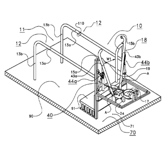
The milking stations 10 are mutually separated by separation fences 12
formed by a horizontal and a vertical bar part 13a, 13b (see figures 2, 3a and
3b). The
horizontal bar part 13a is relatively low, for example around 60-120 cm high.
The cows
8 in adjacent milking stations 10 stand closely next to each other and have
mutual
contact because the milking stations 10 are only separated from each other by
the open
separation fences 12. In this way, the herding behavior of the cows in the
milking
stations 10 is reinforced.
The milking stations 10 each comprise an entry opening 11 for entry of a
cow 8 from the accommodation space 2 to the milking station 10. The entry
opening 11
of each milking station 10 is arranged on one of the short sides of the
milking station 10.
As shown most clearly in figures 2, 3a and 3b, none of the milking stations 10
has an
access gate which is operated by an actuator device between an open state in
which
the entry opening 11 is open, and a closed state in which the entry opening 11
is
closed. The entry openings 11 of the milking stations 10 are each open
permanently.
Incidentally, according to the invention, it is not excluded that a milking
station is taken
out of use by closing the entry opening of that milking station, so that the
milking station
is no longer accessible to milking animals, for example for maintenance or
cleaning
activities in that milking station. During normal operation, the entry
openings 11 are
however permanently open. If a milking station 10 is not occupied by a cow 8,
there is
no obstacle to one of the cows 8 entering said milking station 10 from the
accommodation space 2. The unoccupied milking stations 10 are totally freely
accessible for the cows 8.
On the short sides or head ends opposite to the entry openings 11, the
CA 02996264 2018-02-21
WO 2017/034394 17
PCT/NL2016/050535
milking stations 10 are mutually aligned along a fixed fence 14 (see figure
2). In this
exemplary embodiment, the fence 14 for each milking station 10 has two fence
parts
15a, 15b which, viewed in the transverse direction of the milking station 10,
are
arranged spaced apart from each other, leaving free a central opening 19 with
a first
width WI such that the neck of a cow 8 can pass through as far as the
shoulders. A cow
8 can enter a milking station 10 until the shoulders of the front legs of the
cow 8 come to
rest against the fence parts 15a, 15b on either side of the central opening.
Since the
fence parts 15a, 15b are arranged fixedly, a cow 8 can only leave each milking
station
by walking backward again through the entry opening 11. The entry opening 11
10 therefore also forms an exit opening.
Each milking station 10 furthermore comprises a neck lock device 18
which, in this exemplary embodiment, is arranged on the fence parts 15a, 15b.
The
neck lock device 18 of each milking station 10 can be operated by an actuator
device 40
between a locked state or secured state (see figures 3b and 3d), in which a
cow 8 in the
milking station 10 is held by the neck and hence secured and/or held in the
milking
station 10, and an open state (see figures 3a and 3c), in which a cow 8 is
free to move
its head in and out of the neck lock device 18 and is free to leave the
milking station 10.
Thus the neck lock device 18 of each milking station 10 can be actively
operated. The
neck lock device 18 will be described in more detail below.
In this exemplary embodiment, the milking stations 10 have a drinking
system 16 which is configured to provide water for the milking animals 8. The
drinking
system 16 comprises a plurality of drinking troughs 17; each milking station
10 is
provided with its own drinking trough 17. The drinking troughs 17 are
connected by a
pipe system to a water supply, for example a water mains connection. Water
from the
water mains connection is supplied via the pipe system to the drinking troughs
17. The
water in the separate drinking troughs 17 remains relatively fresh, which is
favorable for
the drinking behavior of the milking animals. It is however also possible that
several
milking stations 10 have a common drinking trough, or even that a single
drinking trough
is provided for all milking stations 10 (not shown).
The drinking trough 17 of each milking station 10 is positioned at a
distance behind the fence parts 15a, 15b of said milking station 10, such that
a cow 8 in
said milking station 10 must push its head and neck through the central
opening 19
between the fence parts 15a, 15b, and through the neck lock device 18 in the
open
state, in order to drink water from the drinking trough 17. In other words,
the drinking
system 16 is configured such that water can only be reached by a cow 8 in a
milking
CA 02996264 2018-02-21
WO 2017/034394 18
PCT/NL2016/050535
station 10 which has pushed its head and neck through the neck lock device 18
in the
open state. In this way, a cow 8 in a milking station 10 which wishes to drink
is secured
safely and reliably at the neck by the neck lock device 18 of said milking
station 10. This
will be explained further below.
In order to identify the cows in the milking stations 10, the system 1 has an
animal identification system, known in itself, for identifying each milking
animal which
visits one of the milking stations. The animal identification system comprises
for
example transponders 23 which are attached to collars worn by the cows 8, and
readout
units 24 for reading the transponders 23. The readout units 24 are arranged at
the head
end of each milking station 10, in particular along the fence 14 (see figure
2). When a
cow 8 walks into one of the milking stations 10 and then pushes its head
through the
fence 14, the transponder 23 in the collar of the cow 8 is read by the readout
units 24 of
said milking station 10, so that the cow 8 is identified. A control system 41,
for example
comprising a computer, laptop and/or smartphone, is actively connected to the
readout
units 24. The identity of the identified cow 8 is entered in the control
system 41.
The cows can be milked in the milking stations 10 by an automatic milking
system 20. With an automatic milking system, the cows voluntarily go to the
milking
stations 10 to be milked. The automatic milking system 20 comprises milking
cups 22.
The milking system 20 is configured to connect the milking cups 22
automatically to the
teats of a cow 8 in a milking station 10, and to milk said cow 8 automatically
provided
that said cow 8 complies with a predefined milking criterion, i.e. is ready
for milking. The
milking system 20 comprises the control system 41 or is actively connected
therewith.
The control system 41 determines whether a cow 8 which is identified on a
visit to a
milking station 10 fulfils the milking criterion, i.e. must be milked.
Different milking
criteria are possible, for example on the basis of the time which has elapsed
since the
last milking of the cow, or on the basis of the expected milk yield, which is
dependent on
the time since the last milking and the milk production rate in the udders,
which can be
calculated from historical data from previous milkings of the cow, or still
other milking
criteria.
The milking stations 10 are placed adjacent to an animal-free space 70
which is closed for the milking animals present in the accommodation space 2.
The
animal-free space 70 forms a "clean" space, i.e. the cows 8 have no access to
the
animal-free space 70 and cannot walk there. The animal-free space 70 has a
substantially flat floor 71. Various components of the milking system 20 are
arranged in
the animal-free space 70. This will be explained further below.
CA 02996264 2018-02-21
WO 2017/034394 19
PCT/NL2016/050535
The automatic milking system 20 comprises a robot device which is
movable relative to the milking stations 10 such that, in each milking station
10, milking
cups 22 can be connected automatically by means of the robot device to the
teats of a
cow 8 present in said milking station 10. The robot device may be configured
in various
ways, for example as an autonomous self-propelled trolley with milking cups 22
(see
figures 1, 2 and 4a - 4d) or as a robot arm (see for example figures 5 and 6a -
6c). The
various embodiments of the automatic milking system 20 will be described in
more
detail below.
In the exemplary embodiment shown, the drinking system 16 of the
milking stations 10 is the only drinking facility for the cows in the
accommodation space
2. In other words, the cows in the accommodation space 2 can only drink from
the
drinking troughs 17 of the milking stations 10. In order to drink, the cows
must visit the
milking stations 10. Since the cows 8 must always drink water, the visit
frequency to the
milking stations 10 is more than sufficient for milking two or three times per
day by
means of the automatic milking system 20. Thus it is not necessary or scarcely
necessary to collect the cows manually for milking. This is a particularly
great
advantage since, in the prior art, collecting cows which do not voluntarily
visit a milking
robot, requires manual labor.
Although the cows can only drink in the milking stations 10, at the same
time the water intake of the cows necessary for milk production is guaranteed.
The
number of milking stations 10 according to the invention is relatively great.
As indicated
above, the accommodation space 2 in this exemplary embodiment is configured to
keep
a predefined number of 60 milking animals. In the prior art, it is normal to
place only one
milking robot in such a production group. According to the invention however,
six
milking stations 10 are provided. With such a number of milking stations, in
practice it
does not occur or rarely occurs that all milking stations 10 are occupied by
cows
simultaneously. Even if cows not ready for milking occupy milking stations 10
for
drinking without being milked, almost always one or more milking stations 10
remain
free in which other cows can drink. Consequently, it is guaranteed that the
cows always
or almost always have unrestricted access to water.
At the same time, it is economically viable to have a relatively large
number of milking stations 10 because the costs per milking station 10 are
particularly
low, since the relatively costly components of the automatic milking system
20, i.e. the
robot device, are shared by the milking stations 10. The robot device is
movable relative
to the milking stations 10 such that, in each milking station 10, milking cups
22 can be
CA 02996264 2018-02-21
WO 2017/034394 20
PCT/NL2016/050535
connected automatically by means of the robot device to the teats of a cow 8
present in
said milking station 10.
The drinking system 16 of the milking stations 10 is furthermore
configured to make water available, in particular in unlimited quantities ( ad
libitum ), for
each cow present in one of the milking stations 10, irrespective of whether or
not said
cow 8 fulfils the milking criterion. In other words, each cow visiting one of
the milking
stations 10 can drink in said milking station 10, irrespective of whether or
not said cow 8
is ready for milking. In this way, the cows are conditioned to associate the
milking
stations 10 primarily with drinking, and only secondarily with milking. The
milking
stations 10 form drinking stations for the cows. Consequently, the cows 8 are
further
encouraged to visit the milking stations 10 voluntarily.
To facilitate the access to water further, the permanently open entry
openings 11 of the milking stations 10 can be reached freely and/or unhindered
via a
walkable connection from the feed fence 4, the concentrate feeding station 6
and from
the lying stalls 9 in the accommodation space 2. The accommodation space 2 is
configured such that the cows can walk around freely in the accommodation
space 2
between the feed fence 4, the lying stalls 9 and each entry opening 11.
Totally free cow
traffic is possible between the feed fence 4, the lying stalls 9 and the entry
openings 11.
To drink water, the cows in the accommodation space 2 are able to walk to the
drinking
system 16 of the milking stations 10 without compulsion and without hindrance.
Therefore with the system according to the invention, not only is it
guaranteed that every cow 8 visits the milking stations 10 frequently, whereby
no cows
or few cows need be collected for milking, but also water is available so
easily that the
water consumption of the cows is comfortably sufficient for optimum milk
production.
Although, in this exemplary embodiment, the drinking system 16 is the
only drinking facility for the cows 8 in the accommodation space 2, the system
according to the invention may comprise a further drinking facility, for
example a
drinking trough in the accommodation space 2. The capacity of the further
drinking
facility is then however selected small enough that, in order to meet their
daily water
.. needs, the cows must still visit the milking stations 10.
In this exemplary embodiment, the neck lock device 18 of each milking
station 10 (see figures 3a - 3d) comprises two retaining posts 43a, 43b, which
are each
pivotable about a respective pivot axis A (see also figure 2) which runs
substantially in a
horizontal plane, obliquely relative to the longitudinal direction of the
milking station 10.
The pivot axes A of the retaining posts 43a, 43b are for example arranged at a
height of
CA 02996264 2018-02-21
WO 2017/034394 21
PCT/NL2016/050535
30 cm. The angle between the pivot axis A of each retaining post 43a, 43b and
the
longitudinal direction of the milking station 10 is around 300 in this
exemplary
embodiment.
As shown in figures 3a and 3c, in the open state of the neck lock device
18, the retaining posts 43a, 43b define a V-shaped opening. A cow 8 walking
into the
milking station 10 first pushes its head through the central opening 19
between the
fence parts 15a, 15b, and through the V-shaped opening to reach the drinking
trough
17. The V-shaped opening is relatively large so that the cow 8 is encouraged
to drink
from the drinking trough 17. In the locked state shown in figures 3b, 3d, the
retaining
posts 43a, 43b run substantially vertically. Between them is a retaining
opening with a
second width w2 which is smaller than the first width vv1 of the central
opening 19
between the fence parts 15a, 15b. The width w2 of the retaining opening is
such that a
cow 8 which pushes its head through the retaining opening cannot then withdraw
it.
The width w2 of the retaining opening is for example 195 mm. With such a
width w2, a cow 8 locked at the neck cannot withdraw its head fully from the
retaining
opening, but can still move to some extent in the longitudinal direction of
the milking
station 10. This freedom of movement is however limited by the fence parts
15a, 15b
which form a stop for the shoulders of the cow 8. The cow 8 can only move its
neck
forward through the retaining opening until the shoulders of its front legs
come to lie
against the fence parts 15a, 15b. By restricting the freedom of movement of
the cow in
the milking station 10, the automatic connection of the milking cups 22 to the
teats of
the cow 8 becomes easier.
The retaining posts 43a, 43b are each connected to one of the fence parts
15a, 15b by means of a hinge arm 44a, 44b. Each hinge arm 44a, 44b consists of
two
arm parts 45a, 46a and 45b, 46b respectively, which are mutually pivotably
connected
by means of a hinge 48. As described above, the neck lock device 18 is
actively
movable by means of the actuator device 40 between the locked state (see
figures 3b
and 3d) and the open state (see figures 3a and 3c). In this exemplary
embodiment, the
actuator device 40 of each neck lock device 18 comprises two pneumatic
cylinders 42a,
42b for moving the respective retaining posts 43a, 43b. To control the
pneumatic
cylinders 42a, 42b, these are actively connected to the control system 41.
The pneumatic cylinders 42a, 42b engage one of the arm parts 45a, 45b
of the hinge arms 44a, 44b. The other arm parts 46a, 46b each comprise a
protruding
lip 47 which forms a stop for the locked state. When the pneumatic cylinders
42a, 42b
are extended, the retaining posts 43a, 43b move from the open state to the
locked
CA 02996264 2018-02-21
WO 2017/034394 22
PCT/NL2016/050535
state, wherein, because of the obliquely running pivot axes A, the retaining
posts 43a,
43b at the same time move slightly forward. When the cow 8 is enclosed, the
retaining
posts 43a, 43b approach the neck of the cow 8 not only from the side but also
to some
extent from the rear, so that the cow 8 does not or scarcely perceives the
movement of
the retaining posts 43a, 43b, even from the corner of its eye. This helps keep
the cow 8
quiet during application of the neck lock.
The pneumatic cylinders 42a, 42b push the arm parts 45a, 45b through a
dead point until the lips 47 of the arm parts 46a, 46b come to lie against the
arm parts
45a, 45b. The retaining posts 43a, 43b have then reached the locked state. The
pneumatic cylinders 42a, 42b need not be dimensioned to absorb, in the locked
state,
forces which the cow 8 may exert to free itself from the neck lock. Such
forces are
dissipated mechanically via the hinge arms 44a, 44b. To open the neck lock 18,
the
retaining posts 43a, 43b are retracted again through the dead point by the
pneumatic
cylinders 42a, 42b.
As described above, the drinking troughs 17 of the drinking system 16 are
configured to provide water for the cows 8. In this exemplary embodiment, each
drinking
trough 17 is provided with a flap or tongue 49, known in itself and operated
by the cow,
which forms a supply valve. The flap 49 is pretensioned in a closed state.
When a cow 8
presses its nose against the flap 49, the flap 49 is moved to an open state
and water
flows into the drinking trough 17. A sensor 50, for example a flow meter, is
provided in
the supply line to the drinking trough 17 (see figures 4a - 4d). The sensor 50
is actively
connected to the control system 41. On the basis of the sensor 50, it is
perceived when
the cow 8 presses its nose against the flap 49. The sensor 50 forms a
detection means
for detecting whether the cow 8 in a milking station 10 has pushed its head
into the
drinking trough 17 of said milking station 10. The detection means may however
also be
configured differently, for example with a sensor for detecting whether a
light beam is
interrupted. It is also possible that the detection means is configured to
detect whether
the cow in a milking station 10 has brought its head above the drinking trough
17,
instead of in the drinking trough 17.
In this exemplary embodiment, the sensor 50 configured as a flow meter
measures the quantity of water supplied to each drinking trough 17. On the
basis of the
quantity of water supplied, the control system 41 can deduce how much water
the cows
8 have drunk during a visit to the milking station 10. Therefore the water
consumption
and drinking behavior of the cows 8 can be monitored individually.
A cow 8 which visits the milking station 10 to drink water from the drinking
CA 02996264 2018-02-21
WO 2017/034394 23
PCT/NL2016/050535
trough 17 pushes its head through the V-shaped opening between the retaining
posts
43a, 43b. The transponder 23 in the collar of the cow 8 is read by the readout
unit 24 of
said milking station 10, so that the cow 8 is identified. Although the readout
unit 24 can
indeed identify the cow 8 by means of the transponder 23, it cannot be
accurately
established whether the cow 8 is in the correct position and/or attitude for
locking at the
neck in the milking station 10. The correct position and/or attitude in the
milking station
can however be established using the sensor 50. When, after identification by
the
transponder 23, the cow 8 operates the flap 49 of the drinking trough 17 with
its nose,
the control system 41 via the sensor 50 establishes that the head of the cow 8
is in the
10 drinking trough 17 and the cow 8 therefore has a position and/or
attitude in the milking
station 10 which is suitable for locking the cow 8 at the neck by means of the
neck lock
device 18 of said milking station 10.
When the control system 41 has established that the cow 8 in the milking
station 10 has a position and attitude which is suitable for locking said cow
8 at the
neck, the control system 41 controls the actuator device 40 of said milking
station 10
such that the cow 8 is locked at the neck. The control system 41 for
controlling the
pneumatic cylinders 42a, 42b is configured and programmed such that the
retaining
posts 43a, 43b are only moved from the open state to the locked state if the
readout unit
24 has identified the transponder of the cow 8 and established, on the basis
of the
sensor 50, that the cow 8 is pressing its nose against the flap of the
drinking trough 17,
i.e. the cow 8 is in the position and attitude in the milking station 10 in
which the cow 8
can be reliably enclosed between the retaining posts 43a, 43b. In other words,
the
control system 41 makes use of the combination of the data from the
transponder
23/readout unit 24 and the sensor 50 to determine whether the cow 8 in the
milking
station 10 has the position and attitude suitable for the neck lock.
On readout of the transponder 23 of a cow 8, the control system 41
furthermore determines whether or not the identified cow 8 fulfils the milking
criterion,
i.e. is/is not ready for milking. According to the invention however, these
data are not
used to operate the retaining posts 43a, 43b from the open state to the locked
state.
According to the invention, locking the cow 8 at the neck is not dependent on
whether
the cow 8 fulfils the milking criterion. It is not relevant whether the cow 8
is ready for
milking or not: both a cow ready for milking and a cow not ready for milking
are locked
by the retaining posts 43a, 43b of the neck lock device 18. The control system
41 is
programmed such that all cows 8 which, on a visit to the milking station 10,
assume the
position and attitude suitable for the neck lock in the milking station 10,
are locked at the
CA 02996264 2018-02-21
WO 2017/034394 24
PCT/NL2016/050535
neck by means of the neck lock device 18. Each cow 8 which walks into a
milking
station 10 and then operates the flap 49 of the drinking trough 17 with its
nose, is
according to the invention then secured at the neck by the retaining posts
43a, 43b.
Because the cows 8 are always locked at the neck when, after walking
into a milking station 10, the cows 8 begin to drink from the drinking trough
17, the cows
8 rapidly become accustomed to the neck lock 18. Consequently, the cows 8
stand
quietly in the milking station 10 when the cows 8 are held at the neck. This
is favorable
for calmness in the herd, and furthermore has the particularly great advantage
that the
milking system 20 can easily and quickly automatically connect the milking
cups 22 in
the case that the cow 8 is ready for milking.
If the cow 8 locked at the neck is not ready for milking, this cow 8 need not
be milked. After locking at the neck, the cow 8 may be released again almost
immediately. The control system 41 is configured to release every cow 8 not
ready for
milking after a predefined period, calculated from the time at which the cow 8
is locked
at the neck. The predefined period in this exemplary embodiment is around 15
seconds,
but may be longer or shorter of course.
If the cow 8 locked at the neck is ready for milking, the control system 41
sends a signal to the milking system 20 to milk said cow 8. The control system
41 is
programmed such that the neck lock device 18 remains locked until the milking
of the
cow 8 is completed. Only when the milking cups have been disconnected is the
neck
lock device operated by the control system 41 from the locked state to the
open state, to
release the cow 8. It is preferred that the neck lock device 18 is opened only
around 5-
minutes after disconnection of the milking cups 22. During this period, the
teat
openings of the milked cow 8 can recover.
25 As described above, in this exemplary embodiment, the entry
openings 11
of the milking stations 10 are permanently accessible for the milking animals
10. The
feature of always locking the cows 8 at the neck however may also be used in a
system
with milking stations which for example comprise an access gate (not shown).
In this
case, the system according to the invention is preferably configured such that
the entry
30 opening 11 of each milking station 10 which is not occupied by milking
animal, is left
open to allow a cow 8 into the milking station 10, irrespective of whether the
cow 8 fulfils
the milking criterion. In other words, if the entry openings 11 of the milking
stations 10
can be closed by an access gate (not shown), the access gates are operated by
the
control system 41 so that each access gate of an unoccupied milking station 10
remains
open. Every cow 8, irrespective of whether or not the cow complies with the
milking
CA 02996264 2018-02-21
WO 2017/034394 25
PCT/NL2016/050535
criterion, can walk into the free milking station 10.
In the exemplary embodiment shown in figures 1, 2 and 4a - 4d, the robot
device of the automatic milking system 20 is configured as an autonomous self-
propelled trolley 21 for connection of the milking cups 22, wherein the
trolley 21 is
connected to the fixed world by means of a flexible connecting string 5
containing one
or more pipes or lines.
The trolley 21 is connected by means of the flexible connecting string 35
to a coupling device 36 which is arranged at a fixed location in the animal-
free space
70, for example on a wall of the barn, i.e. the connecting string 35 is
connected at one
end to the trolley 21 and at the other end to the coupling device 36. The
coupling device
36 comprises a first connector device, while the flexible connecting string
35, at the end
facing away from the trolley 21, is provided with a second connector device
which can
be releasably connected to the first connector device. When the first and
second
connector devices are coupled together, the different pipes or lines of the
connecting
string 35 are connected. This will be explained in more detail below.
The connecting string 35 is configured such that the trolley 21 can travel
over the floor 71 of the animal-free space 70 into each of the milking
stations 10, while
the trolley 21 remains connected to the coupling device 36 by means of the
connecting
string 35. For example, the length and stiffness of the connecting string 35
are adapted
such that the trolley 21 can travel into each milking station 10, up to below
the teats of a
cow 8. In this exemplary embodiment, the connecting string 35 is guided in the
animal-
free space 70 through an eye of a string guide 37 which is movably suspended
on a
guide rail 38. In this way, the connecting string 35 does not obstruct the
trolley 21 in its
travel over the floor 71. Such a string guide is however optional.
Although the connecting string 35 in figures 4a - 4d is indicated
diagrammatically by a single solid line, the connecting string 35 in this
exemplary
embodiment comprises several pipes or lines, as indicated diagrammatically in
figure 7.
The various pipes or lines of the connecting string 35 are described below.
The connecting string 35 comprises four milk lines 80a, 80b, 80c, 80d.
The four milking cups 22, known in themselves, of the trolley 21 each comprise
a teat
space and a pulsation space (not shown). In this exemplary embodiment, each
milking
cup 22 is connected by means of a double-channel hose 66 to a coupling piece
55
which is attached to the trolley 21. Each double-channel hose 66 comprises two
channels (not shown). The one channel of the double-channel hose 66 is a milk-
carrying channel which discharges a mixture of milk and air from the milking
cup 22,
CA 02996264 2018-02-21
WO 2017/034394 26
PCT/NL2016/050535
while the other channel of the double-channel hose 66 forms a vacuum channel
for
application of a pulsating vacuum to the teat space of the milking cup 22. The
vacuum
channel is connected via the coupling piece 55 to a pulsator (not shown),
which is
attached to the trolley 21.
The four milk lines 80a, 80b, 80c, 80d of the connecting string 35 are
connected at one end via the coupling piece 55 to the respective milk-carrying
channels
of the double-channel hoses 66. At the other end, the milk lines 80a, 80b,
80c, 80d are
connected to the coupling device 36. The four milk lines 80a, 80b, 80c, 80d
are each
connected, via the mutually coupled first and second connector devices of the
coupling
device 36 and the connecting string 35 respectively, fluid-tightly and/or air-
tightly to four
milk-carrying lines 57a, 57b, 57c, 57d which are connected to a milk/air
separator 33 for
separating milk and air (see figure 2). The milk/air separator 33 is formed
for example
by a milk jar known in itself. The milk/air separator 33 is fixedly arranged
in the animal-
free space 70.
The milk/air separator 33 is in fluid connection via a milk transport line 34
with a milk storage tank 25 for the cooled storage of milk. The milk storage
tank 25 is
fixedly placed outside the accommodation space 2, for example in the animal-
free
space 70 or elsewhere. The milk transport line 34 comprises a milk pump 32
which
transports milk from the milk/air separator 33 to the milk storage tank 25.
Between the
milk pump 32 and the milk storage tank 25, the milk transport line 34
comprises a three-
way valve 27 for separating pre-milk and/or milk which is unsuitable for human
consumption.
The connecting string 35 furthermore comprises a flexible vacuum line 81
which is in fluid connection with the pulsator attached to the trolley 21. The
flexible
vacuum line 81 connects the pulsator of the trolley 21 to the coupling device
36. The
flexible vacuum line 81 is connected, via the mutually coupled first and
second
connector devices of the coupling device 36 and the connecting string 35
respectively,
air-tightly to a vacuum line 59 which leads to a vacuum source 26. The vacuum
source
26 is placed at a fixed location in the animal-free space 70. The vacuum
source 26 is for
example configured as a vacuum pump, known in itself, with rotation speed
control. The
vacuum source 26 is furthermore connected by means of a vacuum line 58 to the
milk/air separator 33.
In addition, the connecting string 35 comprises a flexible power supply line
85. The power supply line 85 forms part of an electrical connection between
the trolley
21 and an electrical power source 31, for example a high-voltage current
source. The
CA 02996264 2018-02-21
WO 2017/034394 27
PCT/NL2016/050535
trolley 21 comprises several electric motors. For example, the trolley 21 in
this
exemplary embodiment has a drive and steering system for driving and steering
the
trolley 21. The trolley 21 has two tracks 73, and for each track 73 a
respective electric
motor is arranged on the trolley 21 (not shown). In addition, the trolley 21
comprises
electric motors for moving the milking cups 22 relative to the trolley 21 so
that the
milking cups 22 can be connected automatically to the teats of a cow 8. For
teat
detection, the trolley 35 furthermore comprises a camera 74, in particular for
producing
three-dimensional images. Instead of the camera 74, other teat detection means
may
also be used. The electric motors and the camera 74 on the trolley 35 are
supplied with
electrical energy which is supplied via the flexible power supply line 85. At
the coupling
device 36, the power supply line 85 is connected to a supply cable 64, for
example by
means of plugs. The trolley 21 in this exemplary embodiment requires no
electrical
accumulators.
The connecting string 35 furthermore comprises a flexible water line 82,
for example a water hose, which is connected at one end to the trolley 21. On
the trolley
21, water is used for example to rinse the milking cups 22 after milking. The
water line
82 is in fluid connection with the milking cups 22 on the trolley 35 (not
shown). At the
other end, the water line 82 is connected, via the mutually connected
connector devices
of the connecting string 35 and the coupling device 36, fluid-tightly to a
water supply line
62 which is connected to a water connection 29. The water connection 29 is
formed for
example by a tap connected to the water mains.
The connecting string 35 is furthermore provided with a flexible
compressed air line 83. Compressed air is used for example on the trolley 21
to blow
clean a lens of the camera 74 or the milking cups 22 of the trolley 21. The
compressed
air line 82 is connected at one end to the trolley 21, for example in fluid
connection with
a nozzle provided on the trolley 21 (not shown). At the other end, the
compressed air
line 82 is connected, via the mutually connected connector devices of the
connecting
string 35 and coupling device 36, air-tightly to a compressed air line 61
which is
connected to a compressed air source 28.
The connecting string 35 has a flexible data line 86, for example an
ethernet cable, which is connected at one end to a control unit arranged on
the trolley
21 (not shown). The data line 86 is connected via the control unit of the
trolley 21 to the
camera 74 of the trolley 35. In this exemplary embodiment, the image signal
from the
camera 74 is transmitted by the control unit of the trolley 35, via the data
line 86, the
connected connector devices of the connecting string 35 and of the coupling
device 36,
CA 02996264 2018-02-21
WO 2017/034394 28
PCT/NL2016/050535
and a data cable 65, to the control system 41. On the basis of the image
signal of the
camera 74, the control system 41 can determine the position of the teats of a
cow 8. Via
the hard-wired data connection 65, 86, control signals can furthermore be sent
by the
control system 41 to the control unit on the trolley 21. The drive and
steering system of
the trolley 21 is controlled depending on the control signals. Data are sent
from the
trolley 21 to the control system 41 and vice versa via the hard-wired data
connection.
In this exemplary embodiment, the connecting string 35 comprises a
flexible fluid line 84 for disinfectant fluid, which is in fluid connection
with a spray device
arranged on the trolley 21 for spraying disinfectant fluid onto the teats of a
cow 8. The
fluid line 84 for disinfectant fluid is connected in the same manner as
described above,
via the coupling device 36 and an associated line 63, to a holder 30 for
disinfectant. The
sprayer device is aimed for example at one or more brushes for pretreatment of
the
teats of a cow 8 which must be milked. Instead of pretreatment with brushes,
the trolley
21 may contain a pretreatment cup for pretreatment of the teats. In this case,
the fluid
line 84 is connected to the pretreatment cup of the trolley 21.
Also, one or more of the pipes or lines described above of the connecting
string 35 may be omitted. For example, the trolley 21 comprises a holder for
disinfectant, so that disinfectant need not be supplied to the trolley 21 and
the fluid line
84 is not required. In addition to the pipes or lines described above, the
connecting
string 35 may also comprise other pipes or lines and/or cables.
The milking cups 22 of the trolley 21 are arranged on a robot arm
75 which is movable between a lowered state (see figures 4a - 4c) and a raised
state
(see figure 4d). In this exemplary embodiment, the robot arm 75 is connected
to a
chassis of the trolley 21, pivotably between the lowered state and the raised
state. The
robot arm 75 can be driven by means of an electric drive motor (not shown)
which is
actively connected with the control system 41. The milking cups 22 of the
trolley 35 are
tiltable relative to the robot arm 75 between a retracted state (see figures 4
a - c) and an
erected state (see figure 4d). In the retracted state, the milking cups 22 lie
substantially
horizontally, with the openings of the milking cups 22 opposite the direction
of travel of
the trolley 21, while in the erected state the milking cups 22 are tilted
upward, for
example extending substantially vertically upward. In this exemplary
embodiment, the
milking cups 22 are pretensioned in the erected state, for example by means of
a spring
means, and the trolley 21 comprises a tilt drive for tilting the milking cups
22 from the
erected state to the retracted state (not shown). The tilt drive comprises an
electric drive
motor (not shown). The tilt drive is actively connected to the control system
41.
CA 02996264 2018-02-21
WO 2017/034394 29
PCT/NL2016/050535
As shown most clearly in figures 4a - 4d, the milking stations 10 each
comprise a floor with a first floor part 90 and a second floor part 91 which
is raised
relative to the first floor part 90. The first floor part 90 is connected
below the second
floor part 91 to the floor 71 of the animal-free space 70. In this exemplary
embodiment,
the floor 71 of the animal-free space 70 and the first floor part 90 form a
cohesive floor.
The trolley 21 can travel over the flat floor 71 of the animal-free space 70,
under the
second floor part 91, onto the first floor part 90 of each milking station 10.
The raised second floor part 91 is arranged for example 20 cm higher than
the first floor part 90. Such a raised position corresponds in principle to
the normal
height difference between a lying stall and the floor in a barn. The length of
the second
floor part 91, viewed in the longitudinal direction of each milking station
10, is such that
when a cow 8 stands in the milking station 10 with its front legs on the
second floor part
91, the rear legs of said cow 8 stand on the first floor part 90. The length
of the second
floor part in this exemplary embodiment is 50 cm. A cow 8 in a milking station
10 can
only drink from the drinking trough 17 of said milking station if the cow 8
stands with its
front legs on the second floor part 91. When the cow 8 stands with its front
legs on the
second floor part 91, the cow 8 has a position and/or attitude which is
suitable for
connecting the milking cups 22 of the trolley 21 to the teats of said cow 8.
When a cow 8 visits one of the milking stations 10 to drink from the
drinking trough 17 and said cow 8 is ready for milking, the control system 41
controls
the trolley 21 so that the trolley 21 travels automatically over the floor 71
of the animal-
free space 70, onto the first floor part 90 of said milk station 10, to under
the teats of
said cow 8. Since only a restricted height is available under the second floor
part 91, the
trolley 35 with erected milking cups 22 is unable to travel below the second
floor part 91,
even if the robot arm 75 is lowered.
To enable the trolley 21 to travel from the floor 71 of the animal-free space
70, under the fence 14 and the second floor part 91, the milking cups 22 of
the trolley
21, with the robot arm 75 in the lowered state, are tilted down into the
retracted state.
The trolley 21 then fits under the second floor part 91 (see figure 4c). After
the trolley 21
has passed under the second floor part 91, the control system 41 controls the
electric
drive motor of the robot arm 75 to bring this into the raised state, and the
tilt drive to
move the milking cups 22 to the erected state. Then the milking cups 22 are
connected
automatically to the teats of the cow 8 on the basis of control signals from
the control
system 41. The trolley 21 can be moved inside the milking station 10 and/or
the robot
arm 75 can be controlled relative to the trolley 21 to connect the milking
cups 22
CA 02996264 2018-02-21
WO 2017/034394 30
PCT/NL2016/050535
automatically to the teats of a cow 8 in the milking station 10.
During travel over the floor 71 of the animal-free space 70, and up to the
first floor part 90 of the milking station 10, the trolley 21 remains
connected to the
coupling device 36 by means of the flexible connecting string 35. Since the
pipes or
lines of the connecting string 35 are used to discharge the milk, to supply a
vacuum,
water, compressed air and disinfectant, and to exchange data, the trolley 21
can be
configured particularly light and compact.
Also, in an embodiment not shown, according to the invention it is possible
that milk and air discharged from the milking cups 22 are separated from each
other on
the trolley 21. For example, the milking cups 22 are each connected to a
milk/air
separator which is arranged on the trolley 21. The milk/air separator of the
trolley 21 has
a milk discharge opening which is in fluid connection with a milk pump
arranged on the
trolley 21. The milk pump is connected to a single flexible milk line which
extends
through the connecting string 35 to the coupling device 36. Only milk flows
through the
flexible milk line of the connecting string 35. Only one milk line is required
for
transporting the milk. The milk is discharged from the coupling device 36 to
the milk
storage tank 25 as described above. Since the milk pump in this case is
arranged on
the trolley 21, the milk can be transported from the trolley 21 to the milk
storage tank 25
particularly efficiently.
In a further embodiment (not shown), according to the invention, the
system comprises two or more autonomous self-propelled trolleys. For example,
a
second trolley contains a device for pretreatment and/or post-treatment of the
teats of a
cow 8 in a milking station 10. The second trolley can pretreat, for example
clean,
disinfect and/or stimulate, the teats of the cow 8 in a milking station 10,
before the first
trolley 21 automatically connects the milking cups 22 to the teats. In
addition or
alternatively, the second trolley may be configured to post-treat the teats of
the milk cow
8, i.e. after the first trolley 21 has milked the cow 8 and travelled away,
the second
trolley travels under the milk cow 8 for post-treatment. Therefore firstly the
pretreatment
and/or post-treatment, and secondly the milking, are carried out by different
trolleys.
Also, a second trolley may be configured in the same way as the first trolley.
An alternative embodiment of the system is shown in figures 5, 6a - 6c.
The same or similar components carry the same reference numerals. In this
case, the
system comprises a telescopic robot arm 100. The telescopic robot arm 100
comprises
several arm parts 101a, 101b, 101c, 101d which are telescopically connected to
each
other. By extending and retracting the arm parts 101a, 101b, 101c, 101d, the
robot arm
CA 02996264 2018-02-21
WO 2017/034394 31
PCT/NL2016/050535
100 can be moved in the longitudinal direction of the milking station 10. The
first arm
part 101a of the robot arm 100 is fixed to an arm guide 105 which is connected
to a
fixed supporting structure. In this exemplary embodiment, the supporting
structure
comprises a guide rail 106 connected to the floor 71 of the animal-free space
70. The
arm guide 105 with the robot arm 100 attached thereto is guided movably over
the
guide rail 106 by means of rollers, in the transverse direction of the milking
stations 10.
The function of the robot arm 100 is furthermore substantially the same as
that of the
trolley 21 described above, and will not therefore be explained further. It is
also possible
that the flexible connecting string 35 on the robot arm 100 is configured
differently, for
example is replaced by pipes, lines and/or cables which are arranged on the
robot arm
100.
Although the guide rail 106 in this exemplary embodiment is attached to
the floor 71 of the animal-free space 70, the guide rail 106 for the arm guide
105 may
also be suspended. The robot arm 100 may furthermore, instead of a telescopic
arm,
also be configured as a robot arm with several arm parts connected pivotably
relative to
each other (not shown). Instead of a robot arm 100 which can perform a
rectilinear
movement transversely relative to the milking stations 10, according to the
invention it is
also possible that the robot arm is connected to a fixed supporting structure
about a
substantially vertical pivot axis, for example by means of a ball joint. In
this case, the
milking stations may be placed around the pivot axis, i.e. the milking
stations then lie
laterally next to each other in an arc, such that the milking stations are
oriented with
their head sides substantially towards the pivot axis. By pivoting the robot
arm, the robot
arm can be aligned with each of the milking stations so that the robot arm can
connect
milking cups in each milking station. Such robot arms for connection of
milking cups 22
may be designed and produced using techniques known in themselves in practice.
The robot arm 100 shown in figures 5, 6a - 6c is provided with milking
cups 22. The milking cups 22 are arranged on the robot arm 100. During
operation, the
robot arm 100 connects the milking cups 22 one by one to the teats of a cow 8.
It is
however also possible that the milking system 20 is provided with a milking
cup holder
(not shown), configured for holding the milking cups 22 which are not being
used. The
robot arm 100 in this case comprises a gripper member (not shown), which is
configured to take at least one milking cup 22 from the milking cup holder and
connect
this to a teat of a cow 8. During operation, the robot arm 100 takes a first
milking cup 22
from the milking cup holder and connects said milking cup to a teat, then the
robot arm
100 takes a second milking cup 22 from the milking cup holder, and so on.
Also, such a
CA 02996264 2018-02-21
WO 2017/034394 32
PCT/NL2016/050535
robot arm can be produced using techniques known in themselves in practice.
The
milking cup holder with a set of milking cups 22 may be arranged in the animal-
free
space 70, or such a milking cup holder with a set of milking cups 22 may be
arranged in
each milking station 10. With such a robot arm 100, each milking station 10
may
comprise a set of milking cups 22. The milking cups 22 are for example
arranged in sets
in the animal-free space 70 in front of each milking station 10 or in each
milking station
10, for example close to the teats of a cow 8. It is also possible that a
common set of
milking cups 22 is shared by several milking stations 10. The milking cups 22
are then
used successively in several milking stations 10.
After a cow 8 has been milked, in the exemplary embodiments described
above, said cow 8 may remain in the milking station until the cow 8
voluntarily leaves
the milking station, unless the cow 8 complies with a predefined expulsion
criterion and
all milking stations 10 are occupied by other cows. As indicated
diagrammatically in the
figures, each milking station 10 comprises an expulsion means 110 for driving
a cow 8
out of the milking station 10. The expulsion means 110 may be activated, in
each of the
milking stations 10, to give an expulsion stimulus to a milking animal present
in the
milking station 10, to encourage it to leave the milking station 10. The
expulsion means
110 may be configured in various ways, for example for administering an
electric shock
to a cow 8 in the milking station 10. Alternatively or additionally, the
expulsion means
110 may be configured to give a cow 8 an expulsion stimulus in the form for
example of
a light signal, an audible signal or a contact signal, such as by means of a
water-jet, an
air pulse, or a mechanical push or contact element. Also, according to the
invention it is
possible that the expulsion means are movable relative to the milking stations
10, such
that an expulsion stimulus can be given in each milking station 10 to a cow 8
present in
said milking station 10 (not shown). Furthermore, according to the invention
it is
possible that the system 1, instead of or in addition to the expulsion means
110, has an
attraction means and/or other motivation means for giving a stimulus in order
to entice
the cows 8 to leave the milking stations, for example by means of feed
concentrate.
To be able to activate the expulsion means, the expulsion means 110 are
each actively connected to the control system 41. The control system 41
controls the
expulsion means 110 such that the expulsion means 110 are only activated if
two
conditions are fulfilled: (i) a cow 8 in one of the milking stations 10
fulfils the predefined
expulsion criterion, and (ii) all milking stations 10 are occupied. The
expulsion criterion
may comprise different parameters. For example, the expulsion criterion is
dependent
on the milking criterion, such as whether the cow 8 fulfils the milking
criterion or fulfils
CA 02996264 2018-02-21
33
WO 2017/034394
PCT/NL2016/050535
the milking criterion within a predefined period, and/or the visit behavior of
the cow 8,
such as the expected time between two successive visits of the cow 8 to the
milking
stations, and/or the drinking behavior of the cow 8, such as the water intake,
i.e. how
much the cow 8 drinks from the drinking trough, and/or other parameters. The
expulsion
criterion may furthermore be determined individually for each individual cow 8
in the
accommodation space 2. Also with a cow-dependent milking criterion however, an
expulsion criterion may be used which is the same for all cows 8 in the
accommodation
space 2.
As described above, the number of milking stations 10 according to the
invention is selected such that it does not occur or rarely occurs that all
milking stations
10 are occupied simultaneously, i.e. during operation, almost always one or
more
milking stations 10 are free. Since a cow 8 is only expelled from the milking
station if
condition (ii) is fulfilled, i.e. all the milking stations are occupied, a cow
8 is driven out
only in very exceptional cases. This has a positive effect on the extent to
which the
cows 8 voluntarily visit the milking stations 10. The system according to the
invention is
configured to allow every cow 8 visiting a milking station 10 to remain there
in principle
until said cow 8 voluntarily leaves the milking station. The milking animals
are only
subjected to expulsion stimuli, which are perceived by the cows 8 as
uncomfortable, in
the exceptional circumstance that all milking stations 10 are occupied. In
addition, the
control system 41 also determines whether the cow 8 to be driven out complies
with the
predefined expulsion criterion.
Instead of driving out cows by means of the expulsion means 110 only in
very exceptional circumstances, according to the invention it is also possible
to allow
the cows always to remain in the milking stations until the cows voluntarily
leave the
milking stations. In this case, no expulsion means 110 are required, i.e. the
expulsion
means 110 are omitted in this embodiment (not shown). None of the milking
stations 10
comprises expulsion means. Also, the system does not comprise any attraction
means
or other motivation means for encouraging the cows 8 to leave the milking
stations. The
cows 8 may remain in the milking stations 10 until the cows 8 voluntarily
leave the
milking stations 10. As described above, the cows 8 have access to the milking
stations
10 irrespective of whether or not the cows 8 fulfil the milking criterion,
i.e. irrespective of
whether the cows 8 must be milked. Both cows 8 which have been milked, and
cows 8
which visit the milking stations 10 to drink without needing to be milked, may
remain in
the milking stations 10. In this case, it cannot be completely excluded that
all milking
stations 10 are occupied at some time by the cows 8. If all milking stations
10 are
84184687
34
occupied, a cow 8 from the accommodation space 2 which wishes to drink, must
wait until
one of the cows 8 voluntarily leaves the milking station 10. As explained
above, the number
of milking stations 10 is however sufficiently great, relative to the number
of cows 8 contained
in the accommodation space 2, that the risk is minimal that all milking
stations 10 will remain
occupied simultaneously for an unacceptable period.
The invention is not restricted to the exemplary embodiments shown in the
drawing. The person skilled in the art may make various adaptations which lie
within the
scope of the invention. The features described above may be used both
separately and in
any arbitrary combination, and/or be combined with one or more features which
follow. In
particular, according to the invention, the drinking system with drinking
troughs 17 may be
replaced by a feed and/or drinking system for providing feed and/or water for
the milking
animals. The feed and/or drinking system comprises for example a feed and/or
drinking
trough for each milking station. The milking animals then visit the milking
stations to eat and/or
drink. Furthermore, according to the invention, it is possible that the
system, instead of the
neck lock device described in the description and disclosure below, comprises
another
holding device for securing and/or holding a milking animal in a milking
station. For example,
each milking station has a holding device which can be operated by means of an
actuator
device between a holding state, in which a milking animal present in said
milking station is
held by the holding device, and a free state, in which a milking animal
present in said milking
station is free to leave said milking station. Such a holding device for
example comprises a
door or gate to enclose a milking animal in a milking station, such as in a
generally known
milking stall.
Date Recue/Date Received 2022-09-14