Note: Descriptions are shown in the official language in which they were submitted.
CA 02996503 2018-02-23
WO 2017/015674
PCT/US2016/043944
SYSTEM AND METHOD FOR DELIVERING LIGHT DOSE TO TISSUE
Statement Regarding Federally Sponsored Research
[0001] This invention was made with government support under contract
no.
P01CA55791 awarded by the National Institutes of Health. The government has
certain rights in
the invention.
Cross-Reference to Related Applications
[0002] This application claims priority to U.S. Provisional
Application No. 62/196,290,
filed on July 23, 2015, now pending, the disclosure of which is incorporated
herein by reference.
Field of the Disclosure
[0003] The present disclosure relates to non-ionizing light therapy.
Background of the Disclosure
[0004] Light therapy can be used for treatment of conditions in
multiple ways. For
example, interstitial light therapies (ILT) involve the delivery of a
therapeutic light through a
fiber optic placed within a target tumor. Other therapies involve treatment
with a light does at or
above the tissue surface.
[0005] ILT can be combined with prior administration of light
sensitive medicine (i.e.,
photosensitizer) that absorbs the therapeutic light and interacts with
surrounding tissue
constituents (e.g., oxygen) to generate reactive species that can destroy the
target tissue. This
form of therapy is known as photodynamic therapy ("PDT"). PDT uses light (such
as light
provided by a laser) to activate a non-toxic drug called a photosensitizer.
The process works in
three ways: it destroys cancer, shuts down blood vessels that "feed" the
tumor, and prompts the
immune system to kill cancer cells throughout the body. It is associated with
mild side effects
and can be combined with standard chemotherapy and surgery, and followed with
radiation
therapy.
[0006] In addition or alternatively, the energy of the light can be
absorbed by blood or
external additives (such as metal particles) that convert the light energy
into heat, to induce
complete destruction of the target tissue.
1
SUBSTITUTE SHEET (RULE 26)
CA 02996503 2018-02-23
WO 2017/015674 PCT/US2016/043944
[0007] In all light therapies, whether interstitial or not, whether
PDT or not, it can be
important that the entire tumor be illuminated with sufficient dose light in
order to administer a
successful treatment. To that end, proper treatment planning and control must
be used.
[0008] The efficacy of photodynamic therapy is determined in part by
photosensitizer
availability and radiant exposure. Photofrin and other photodynamic
sensitizers can be degraded
by light exposure, a process called photobleaching, and this can be measured
by loss of
photosensitizer characteristic fluorescence. In addition, photobleaching has
been shown to
provide a prediction of the photodynamic dose delivered. However, quantitative
measures of
photosensitizer fluorescence can be complicated by changes in tissue optical
properties during
PDT. Accordingly, there is a need for tools to measure photosensitizer
concentration and optical
properties in target tissue can improve the accuracy of photodynamic dose
calculation.
Brief Summary of the Disclosure
[0009] The present disclosure may be embodied as a method for
interstitial
photodynamic light therapy (I-PDT) of a tissue. A plurality of light-
transmitting catheters
(LTCs) are provided and placed in the tissue according to a pre-determined
treatment plan,
wherein at least one LTC of the plurality of LTCs includes a first treatment
fiber disposed
therethrough, and at least one LTC of the plurality of LTCs includes a
dosimetry fiber disposed
therethrough. A dose light is provided to the tissue by way of the first
treatment fiber according
to the pre-determined treatment plan. Light received at the dosimetry fiber is
measured using a
spectrometer in operable communication with the dosimetry fiber. One or more
properties of a
photosensitizer in the tissue are determined. The treatment plan is modified
based on the
properties of the photosensitizer, and an updated dose light is provided to
the tissue by way of
the first treatment fiber according to the modified treatment plan.
Description of the Drawings
[0010] For a fuller understanding of the nature and objects of the
invention, reference
should be made to the following detailed description taken in conjunction with
the
accompanying drawings, in which:
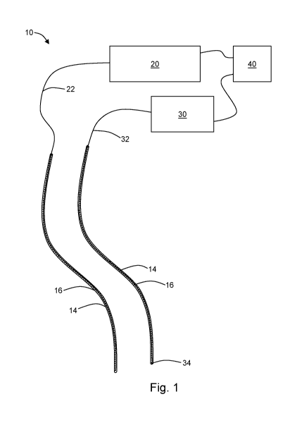
Figure 1 is a system according to an embodiment of the present disclosure;
2
CA 02996503 2018-02-23
WO 2017/015674 PCT/US2016/043944
Figure 2 is a detail view of an embodiment of a light-transmitting catheter
and treatment
catheter;
Figure 3 is a photograph showing an exemplary system according to an
embodiment of
the present disclosure having (a) 8 calibrated spectrometers for measuring
dose light,
(b) treatment laser with delivery fibers, and (c) calibration light source and
integrating
sphere for calibration of dosimetry fibers;
Figure 4 depicts an exemplary screen of the controller used in the system of
Figure 3
wherein (a) is an input value for setting the integration time or acquisition
time, (b) is
a capture dark button to remove background light and electronic noise, (c) is
a grid to
present and record the relative location of the detection fibers and the laser
treatment
fiber(s), (d) is a file name that is assigned to each measurement, (e) is a
slide bar to
select the range of wavelength to be monitored according to the wavelength of
the
treatment light, (0 is a graph to plot the power or energy as function of
wavelength
detected by each detector and spectrometer, (g) is a start, stop and
preferences and
reset buttons, and (h) a number of columns presenting the detector number,
fluence
rate (mW/cm2), dose light (J/cm2) and time to target, which is the time that
required
depositing a prescribed dose light in this location;
Figure 5 depicts an I-PDT treatment schematic according to an embodiment of
the
present disclosure showing where treatment fibers are inserted through
transparent
catheters (light-transmitting catheters, or LTCs);
Figure 6 depicts the geometry of Figure 5, having an array of six LTCs
inserted within
the tumor, and a volumetric mesh for finite element modeling;
Figure 7 is the calculated dose light (J/cm2) distribution within the target
tumor of
Figures 5 and 6;
Figure 8 is the calculated dose light distribution within the non-tumor
tissue, suggesting
that only a small portion of the non-tumor tissue will be exposed to a dose
light that
can induce I-PDT (20 J/cm2 or greater);
Figure 9 depicts an exemplary embodiment of the present disclosure;
Figure 10 is a graph showing Photofrin fluorescence excited at 410 nm in
liquid phantom
containing fetal calf serum;
Figure 11 is a graph showing Photofrin fluorescence excited at 410 nm in
liquid optical
phantom containing 2.6 M hemoglobin and 1 p.m microspheres; psi = 5.0 cm-I);
3
CA 02996503 2018-02-23
WO 2017/015674 PCT/US2016/043944
Figure 12 is a graph showing the signal detected across 0.44 cm of the liquid
optical
phantom of figure 11, where the source light was at 690 nm; and
Figure 13 is a chart of a method according to another embodiment of the
present
disclosure.
Detailed Description of the Disclosure
[0011] The present disclosure provides a method and system for light
therapy treatment
that enable complete and adequate illumination of an entire tumor and margins.
The present
techniques may be used for real-time dosimetry of therapeutic light delivered
to an individual. It
should be noted that, although the present disclosure is described with
reference to interstitial
photodynamic therapy (I-PDT), the disclosure should not be limited to I-PDT.
It will be apparent
to one having skill in the art in light of the disclosure that the disclosed
systems and methods can
be used for other modalities of non-ionizing light therapy. And such
applications make up a part
of the scope of this disclosure.
[0012] With references to figure 6, the present disclosure may be
embodied as a
system 10 for light therapy, such as, for example, I-PDT. Such I-PDT may be
used to treat a
tissue, for example, a tumor. The system 10 includes at least two light-
transmitting catheters
(LTCs) 14. Each catheter 14 includes a lumen 16. The catheters 14 are
transparent over at least a
distal end, such that treatment light can be transmitted through a wall of the
catheter (i.e., from a
location within the lumen 16 to a location outside of the catheter 14). The
distal ends of the
LTCs 14 are configured to be inserted into the tissue to be treated. In an
exemplary embodiment,
the lumen 16 of each LTC 14 is 1.5 mm in diameter. Other diameters can be used
and will be
apparent in light of the present disclosure. Embodiments of the system 10 may
have 1 to 50
LTCs or more. In an exemplary embodiment, six catheters 14 are provided.
[0013] The system 10 includes a light source 20. In some embodiments,
the light
source 20 is a laser. The light source 20 is in operable communication with at
least one treatment
fiber 22. The at least one treatment fiber 22 is configured to be disposed
through the lumen 16 of
the catheter 14. A treatment fiber 22 is configured to transmit light from the
light source 20 to a
distal tip 24 of the fiber 22. In this way, therapeutic light can be
introduced into the tissue to be
treated. In some embodiments, more than one treatment fiber 14 is used. In the
exemplary
embodiment, four treatment fibers 22 are used, although embodiments may have
more or less
than four. The treatment fibers 22 each have a diffuse tip for emitting light
within the tissue. In
4
CA 02996503 2018-02-23
WO 2017/015674 PCT/US2016/043944
an exemplary embodiment, a treatment fiber 22 has a diameter of .98 mm. Such a
treatment
fiber 22 may be disposed through a lumen 16 having a diameter of, for example,
1.5 mm.
[0014] The system 10 includes a dosimetry fiber 32 configured to be
disposed through
the lumen 16 of an LTC 14. A dosimetry fiber 32 is configured to transmit
light from a receiving
end 34 of the dosimetry fiber 32 to a proximal end. A spectrometer 30 is in
operable
communication with the proximal end of the dosimetry fiber 32. In this way,
light received at the
receiving end 34 can be measured by the spectrometer 30. An exemplary
dosimetry fiber 32 is
0.2 mm in diameter. Such a dosimetry fiber may be used with a catheter 14
having a lumen 16
which is, for example, 1.5 mm in diameter. It should be noted that the
catheter 14, treatment
fiber 22, and dosimetry fiber 32 can be configured such that both a treatment
fiber 22 and a
dosimetry fiber 32 may be disposed through the same catheter 14. In the
exemplary embodiment,
the system 10 includes eight dosimetry fibers 32, although more or less
dosimetry fibers can be
used. Each dosimetry fiber 32 / spectrometer 30 pair may be calibrated with a
light source and
integrating sphere that were in turn calibrated with a National Institute of
Standards and
Technology (NIST) traceable standard.
[0015] Advantageously, each treatment fiber 22 and/or dosimetry fiber
32 can be used
for one or more wavelengths. For example, a dosimetry fiber 32 can be used to
detect a single
wavelength or multiple wavelengths (for example, broadband detection). In
embodiments using
multiple dosimetry fibers 32 the fibers need not be used for the same
wavelength as one another.
The present use of a spectrometer 30 allows for broad detection of
wavelengths. Similarly,
treatment fibers 22 need not be used for the same wavelengths as one another.
The wavelengths
and ranges of wavelengths can be changed during treatment. As such, the
present system 10
provides a great deal of flexibility in treating different tumors, using
different drugs, etc.
[0016] The system 10 further comprises a controller 40. The controller
40 is configured
to adjust the light delivered by the light source 20. In this way, light may
be provide to a tissue
from a light source 20 connected to one or more treatment fibers 22, and the
light may be
provided according to a treatment plan by way of control by the controller 40.
The controller 40
may be, for example, a computer or any other suitable control device. The
controller 40 may be
programmed to control each spectrometer 30 / dosimetry fiber 32 pair and
record the dose light
and fluence rate (W/cm2). An exemplary control panel for a controller 40 is
shown in Figure 3,
5
CA 02996503 2018-02-23
WO 2017/015674 PCT/US2016/043944
below. The system 10 may be designed to continuously monitor and record the
delivered and
transmitted dose light.
[0017] In an exemplary embodiment, a light-transmitting catheter 52 is
advantageously
designed with a tip 54 configured to enhance light reception, for example, a
conical tip. Such a
tip 54 can be used to pierce tissue in order to place the catheter 52 into a
desired position. The
lumen 56 may have a flat end 58 at or near the base of the conical tip 54. In
such an embodiment,
a therapy fiber 60 may be cleaved with a flat tip 62. In this way, the therapy
fiber 60 can be
disposed into the lumen 56 of the catheter 52 until the flat tip 62 abuts the
flat end 58. In some
embodiments, light emitted from the flat tip 62 of the catheter 52 will be
diffused or otherwise
spread by the conical tip 54.
[0018] Embodiments of the present disclosure may be used to provide
therapeutic light
according to a pre-determined treatment plan. Such treatment plans are known
in the art to be
determined based on models an assumptions of the tissue to be treated. The
present disclosure
advantageously allows for modification of the treatment plan according to
light received by the
dosimetry fiber(s) and measured by the corresponding spectrometer(s). For
example, the optical
properties of the tissue may be different than the optical properties modelled
for the pre-
determined treatment plan. The optical properties of the actual tissue may be
determined based
on the light measured by the spectrometers. These actual optical properties
can then be used to
recalculate/modify the treatment plan to better suit the tissue being treated.
Such modification
may be done in real-time. In this way, the presently disclosed techniques may
provide more
accurate and/or efficient dose lights (e.g., treating a tumor and its margins
while minimizing the
exposure of the surrounding tissue).
[0019] In an example where a tumor is to be treated (see, e.g., Figure
5), a computed
tomography (CT) or magnetic resonance (MR) image is used to obtain an image of
the target
tumor. Software is used to create a 3D model of the geometry of the target
tissue and relevant
anatomical structures (see, e.g., Figure 6). A computer simulation is used to
calculate the number
and location of light transparent catheters 14 through which the treatment
fibers 22 will be
inserted for illuminating the tumor and margins. During therapy, a physician
uses the simulation
to decide where it would be best to insert catheters 14. Prior to insertion,
the physician utilitizes
standard medical imaging (typically ultrasound) to image the sites of where
the LTCs will be
inserted, to assure patient's safety. Insertion may be accomplished using, for
example, real-time
6
CA 02996503 2018-02-23
WO 2017/015674 PCT/US2016/043944
image guidance using ultrasound or CT, or insertion can be guided with a
robotic arm that will
register the location in 3-D with reference to the images simulation, model,
and/or images
described above.
[0020] Once the LTCs 14 are in place, ultrasound, MRI, or CT can be
used to measure
the actual location of the fibers and each LTC 14 is marked with a number. A
target dose light is
prescribed for each location. The target light does is the amount of light
that should be delivered
from each treatment fiber 22 at a specific LTC 14. The target dose light is
based on prior clinical
data or prior work in pre-clinical settings that showed promising results in
an effective drug
activation and response to I-PDT or ILT.
[0021] Treatment fibers 22, dosimetry fibers 32, or both are placed in the
various marked
LTCs 14. The number of LTCs can be 1-50 or more, and the number of dosimetry
fibers may be
1-8 (but can be as high as 24 or more). In some embodiments, more dosimetry
fibers than
treatment fibers are placed in the LTC array. In some embodiments, the
diameter of our
dosimetry fibers is 0.2 mm, the diameter of the treatment fibers is 0.98 mm,
and the inside
diameter of the LTCs is about 1.5 mm; as such, a dosimetry fiber and a
treatment fiber may be
placed in the same LTC. This combination allows measurement of the light
output from
treatment fibers during therapy, and the light delivery to nearby LTCs that
have no treatment
fibers.
[0022] Measuring the dose light from the treatment fibers and at a
distance is not trivial,
because the dose light next to the treatment fiber is much higher than the
dose as measured from,
for example, 10 mm away. Obtaining both dosage measurements (near and far) at
the same time
is beneficial, because it allows for calculating optical properties in real
time. Embodiments of the
present disclosure allow measurement of very high and relatively low dose
lights at the same
time by modifying the acquisition time of a measurement in order to record a
wide range of dose
lights.
[0023] The real-time measurement data may then be used to calculate
the optical
properties within the treated tumor. In some embodiments, a look-up table may
be provided for
determining relevant optical properties from measured values of light dosage.
These optical
properties can then be used to recalculate the light distribution within the
target tumor¨thereby
modifying the treatment plan. As such, regions of the tumor and/or surrounding
tissue can be
identified as being over treated or under treated (see Figures 6-8).
7
CA 02996503 2018-02-23
WO 2017/015674 PCT/US2016/043944
[0024] In a simulation of the exemplary method, therapy required 1-1.5
min, whereas a
typical therapy takes at least 20-30 minutes. The presently disclosed system
is suitable for any
drug and light wavelength in the range of, for example, 400-1200 nm. The
presently disclosed
systems and methods are suitable for use on heterogonous tumors such as, for
example, head or
neck cancer.
[0025] In another aspect, the present disclosure is embodied as a
method 100 for
interstitial photodynamic light therapy (I-PDT) of a tissue (see, e.g., Figure
13). The method 100
includes providing 103 a plurality of light-transmitting catheters (LTCs)
placed in the tissue
according to a pre-determined treatment plan. At least one LTC of the
plurality of LTCs includes
a first I-PDT treatment fiber disposed therethrough. At least one LTC of the
plurality of LTCs
includes a dosimetry fiber disposed therethrough. A dose light is provided 106
to the tissue by
way of the treatment fiber according to the pre-determined treatment plan (as
discussed above).
[0026] Light received at the dosimetry fiber is measured 109 using a
spectrometer in
operable communication with the dosimetry fiber. The light measured 109 at the
dosimetry fiber
may be a measurement light. The measurement light may be a different
wavelength from that of
the dose light. In some embodiments, the measurement light is the same
wavelength as light
emitted by a photosensitizer when the photosensitizer is excited. For example,
when Photofrin is
used, the dose light may be at 630 nm and the measurement light may be at 690
nm. In some
embodiments, the measurement light is provided by a second treatment fiber. In
such cases, the
method 100 includes providing 121 a second treatment fiber in an LTC which is
different from
the LTC of the first treatment fiber. The dose light may be stopped 124 during
a time of light
measurement 109 at the dosimetry fiber.
[0027] One or more properties of a photosensitizer in the tissue are
determined 112 based
on the light measured 109 at the dosimetry fiber. For example, the rate and/or
response of the
photosensitizer may be determined 112. The treatment plan is modified 115
based on the
determined 112 properties of the photosensitizer. An updated dose light is
provided 118 to the
tissue by way of the treatment fiber(s) according to the modified treatment
plan.
EXEMPLARY EMBODIMENTS
[0028] In the exemplary embodiment depicted in Figure 9, catheter A
contains two
optical fibers, Al and A2. The excitation fiber Al (i.e., the treatment fiber)
delivers light to
8
CA 02996503 2018-02-23
WO 2017/015674 PCT/US2016/043944
excite the photosensitizer to generate singlet oxygen for PDT of the target
tissue. For example,
for Photofrin, the delivered light is at 630 nm. This same light also excites
characteristic
fluorescence emission of Photofrin at 690 nm. The detection fiber A2 (i.e.,
the dosimetry fiber) is
attached to a spectrometer to measure fluorescence emission wavelength and
intensity.
Alternatively, fiber Al can deliver 405 nm light to provide a much stronger
fluorescence signal
because: (i) Photofrin absorbs light at 410 nm ¨15-fold more than at 630 nm;
and (ii) excitation
at 405 nm light will result in two emission bands (630 nm and 690 nm).
[0029] In the exemplary embodiment, catheter B contains a single
fiber. Source fiber B1
emits light (for Photofrin, 690 nm) that travels through tissue and is
collected by detection
fiber A2 in catheter A. The intensity of the light collected by fiber A2 is
used to monitor changes
in tissue optical properties during the course of therapy. To do this, the 630-
nm light is
momentarily turned off so that only 690-nm light from source Bl, and not
Photofrin-
characteristic fluorescence emission at 690 nm, will be collected.
[0030] Proof of principle for fluorescence detection of Photofrin was
demonstrated in
solution, containing phosphate buffered saline, 10% fetal calf serum and 5
g/mL Photofrin.
12 mL of solution was placed in a black, light-tight Delrin well. The well-
cover included ports to
allow insertion of closed-end, 15G polycarbonate Flexi-Needle needle guide
catheters into the
well.
[0031] Excitation fiber Al was a Medlight RD20 fiber-optic with a 2-cm
length
cylindrical diffuser; this fiber was attached to either a Modulight 630-nm
laser diode or
Powertech Inc. 410-nm laser diode. Detection fiber A2 was a 200 p.m, flat-cut,
0.22 NA quartz
fiber-optic; this fiber was attached to an Ocean Optics USB200+ spectrometer.
Fluorescence
()Lex = 410 nm) from Photofrin in solution is shown in Figure 10.
[0032] In a subsequent study, a more robust liquid optical phantom was
prepared from a
mixture of microspheres and hemoglobin (Hb) (experimental conditions are shown
in Figures 11
and 12). Figure 11 shows the detection of backscattered Photofrin fluorescence
using 410 nm
(fiber Al) and detection fiber A2 placed in catheter A. Figure 12 shows the
detection of 690 nm
light from source fiber B1 to detection fiber A2 through 5 mm of liquid
optical phantom.
[0033] Although the present disclosure has been described with respect
to one or more
particular embodiments, it will be understood that other embodiments of the
present disclosure
9
CA 02996503 2018-02-23
WO 2017/015674
PCT/US2016/043944
may be made without departing from the spirit and scope of the present
disclosure. Hence, the
present disclosure is deemed limited only by the appended claims and the
reasonable
interpretation thereof