Note: Descriptions are shown in the official language in which they were submitted.
TRACK SYSTEM FOR TRACTION OF A VEHICLE
FIELD
The invention relates generally to off-road vehicles (e.g., snowmobiles, snow
bikes, all-
terrain vehicles (AN), agricultural vehicles, etc.) and, more particularly, to
track systems
for traction of such vehicles.
BACKGROUND
Certain off-road vehicles may be equipped with track systems which enhance
their
traction and floatation on soft, slippery and/or irregular grounds (e.g.,
snow, ice, soil, mud,
sand, etc.) on which they operate.
For example, snowmobiles allow efficient travel on snowy and in some cases icy
grounds.
A snowmobile comprises a track system which engages the ground to provide
traction.
The track system comprises a track-engaging assembly and a track that moves
around
the track-engaging assembly and engages the ground to generate traction. The
track
typically comprises an elastomeric body in which are embedded certain
reinforcements,
such as transversal stiffening rods providing transversal rigidity to the
track, longitudinal
cables providing tensional strength, and/or fabric layers. The track-engaging
assembly
comprises wheels and in some cases slide rails around which the track is
driven.
1
Date Recue/Date Received 2022-10-21
CA 02996648 2018-02-26
WO 2017/031591 PCT/CA2016/051004
A snowmobile's user often leans on a side of the snowmobile in order to adjust
the
snowmobile's course and/or to stabilize the snowmobile over uneven terrain. In
some
cases, the user may even stand on the side of the snowmobile (generally known
as
"sidehilling"). Such practices subject the snowmobile to an off-centered
loading (i.e., a
loading offset from a center of the snowmobile along a widthwise direction of
its track
system) which can cause part of its track to apply less pressure onto the
ground. The
track may thus generate less traction on the ground in such instances.
A snow bike, which is a motorcycle equipped with a ski system and a track
system
respectively replacing its front and rear wheels, may similarly experience a
decrease in
traction when its rider leans towards a side of the snow bike.
Similar considerations may arise for track systems of other types of off-road
vehicles
(e.g., all-terrain vehicles (ATVs), agricultural vehicles, or other vehicles
that travel on
uneven grounds) in certain situations.
For these and other reasons, there is a need to improve track systems for off-
road
vehicles.
SUMMARY
In accordance with various aspects of the invention, there is provided a track
system for
traction of a vehicle. The track system comprises a track and a track-engaging
assembly for driving and guiding the track around the track-engaging assembly.
The
track system may be configured to enhance traction of the vehicle on the
ground, such
as by maintaining proper contact on the ground when the vehicle is leaned
(e.g., for
steering and/or over uneven terrain) and/or when the track system is subject
to other
loading that would otherwise tend to reduce tractive forces that it generates.
For
instance, the track system may be configured such that, when the vehicle
travels on the
ground, a surface of the track-engaging assembly in contact with a bottom run
of the
track is movable relative to a frame of the vehicle to change an orientation
of the
2
surface of the track-engaging assembly in contact with the bottom run of the
track relative
to the frame of the vehicle.
According to a general aspect of the disclosure, there is provided a track
system for
traction of a vehicle, the track system comprising: a track comprising a
ground-engaging
outer side for engaging the ground and an inner side opposite to the ground-
engaging
outer side; and a track-engaging assembly for driving and guiding the track
around the
track-engaging assembly, the track-engaging assembly comprising: a drive wheel
for
driving the track; and an elongate support comprising a rail extending in a
longitudinal
direction of the track system along a bottom run of the track, the elongate
support
comprising a sliding surface for sliding on the inner side of the track along
the bottom run
of the track, the rail comprising an upper portion and a lower portion between
the upper
portion and the sliding surface, wherein, when the vehicle travels on the
ground, the upper
portion of the rail is movable relative to the sliding surface to change an
orientation of the
upper portion of the rail relative to the sliding surface; wherein the lower
portion of the rail
is resiliently deformable to allow movement of the upper portion of the rail
relative to the
sliding surface; and wherein a stiffness of the lower portion of the rail is
less than a
stiffness of the upper portion of the rail.
According to another general aspect, there is provided a track system for
traction of a
vehicle, the vehicle comprising a frame and a powertrain mounted to the frame,
the track
system comprising: a track comprising a ground-engaging outer side for
engaging the
ground and an inner side opposite to the ground-engaging outer side; and a
track-
engaging assembly for driving and guiding the track around the track-engaging
assembly,
the track-engaging assembly comprising: a drive wheel for driving the track;
and a rail
extending in a longitudinal direction of the track system along a bottom run
of the track,
the rail overlapping a centerline of the track in a widthwise direction of the
track system;
wherein, when the vehicle travels on the ground, a surface of the track-
engaging
assembly in contact with the bottom run of the track is movable relative to
the frame of
the vehicle to change an orientation of the surface of the track-engaging
assembly in
contact with the bottom run of the track relative to the frame of the vehicle;
and wherein
the vehicle is one of a snow bike and an ATV.
3
Date Recue/Date Received 2022-10-21
According to another general aspect, there is provided a track system for
traction of a
motorcycle, the track system being mountable in place of a rear wheel of the
motorcycle,
the track system comprising: a track comprising a ground-engaging outer side
for
engaging the ground and an inner side opposite to the ground-engaging outer
side; and
a track-engaging assembly for driving and guiding the track around the track-
engaging
assembly, the track-engaging assembly comprising: a drive wheel for driving
the track;
and an elongate support comprising a rail extending in a longitudinal
direction of the track
system along a bottom run of the track, the elongate support comprising a
sliding surface
for sliding on the inner side of the track along the bottom run of the track,
the rail
comprising an upper portion and a lower portion between the upper portion and
the sliding
surface, wherein, when the motorcycle travels on the ground, the upper portion
of the rail
is movable relative to the sliding surface to change an orientation of the
upper portion of
the rail relative to the sliding surface.
According to another general aspect, there is provided a track system for
traction of a
vehicle, the track system comprising: a track comprising a ground-engaging
outer side
for engaging the ground and an inner side opposite to the ground-engaging
outer side;
and a track-engaging assembly for driving and guiding the track around the
track-
engaging assembly, the track-engaging assembly comprising: a drive wheel for
driving
the track; and an elongate support comprising a rail extending in a
longitudinal direction
of the track system along a bottom run of the track, the elongate support
comprising a
sliding surface for sliding on the inner side of the track along the bottom
run of the track,
the rail comprising an upper portion and a lower portion between the upper
portion and
the sliding surface, wherein, when the vehicle travels on the ground, the
upper portion of
the rail is movable relative to the sliding surface to change an orientation
of the upper
portion of the rail relative to the sliding surface; wherein the lower portion
of the rail is
resiliently deformable to allow movement of the upper portion of the rail
relative to the
sliding surface; and wherein a stiffness of the lower portion of the rail is
no more than
1.0E4 GPa/mm4.
3a
Date Recue/Date Received 2022-10-21
According to another general aspect, there is provided a track system for
traction of a
vehicle, the track system comprising: a track comprising a ground-engaging
outer side
for engaging the ground and an inner side opposite to the ground-engaging
outer side;
and a track-engaging assembly for driving and guiding the track around the
track-
engaging assembly, the track-engaging assembly comprising: a drive wheel for
driving
the track; and an elongate support comprising a rail extending in a
longitudinal direction
of the track system along a bottom run of the track, the elongate support
comprising a
sliding surface for sliding on the inner side of the track along the bottom
run of the track,
the rail comprising an upper portion and a lower portion between the upper
portion and
the sliding surface, wherein, when the vehicle travels on the ground, the
upper portion of
the rail is movable relative to the sliding surface to change an orientation
of the upper
portion of the rail relative to the sliding surface; wherein the lower portion
of the rail is
resiliently deformable to allow movement of the upper portion of the rail
relative to the
sliding surface; and wherein a modulus of elasticity of a material of the
lower portion of
the rail is no more than 10 GPa.
According to another general aspect, there is provided a track system for
traction of a
vehicle, the track system comprising: a track comprising a ground-engaging
outer side
for engaging the ground and an inner side opposite to the ground-engaging
outer side;
and a track-engaging assembly for driving and guiding the track around the
track-
engaging assembly, the track-engaging assembly comprising: a drive wheel for
driving
the track; and an elongate support comprising a rail extending in a
longitudinal direction
of the track system along a bottom run of the track, the elongate support
comprising a
sliding surface for sliding on the inner side of the track along the bottom
run of the track,
the rail comprising an upper portion and a lower portion between the upper
portion and
the sliding surface, wherein, when the vehicle travels on the ground, the
upper portion of
the rail is movable relative to the sliding surface to change an orientation
of the upper
portion of the rail relative to the sliding surface; wherein the lower portion
of the rail is
resiliently deformable to allow movement of the upper portion of the rail
relative to the
sliding surface; and wherein the lower portion of the rail comprises a
polymeric material.
3b
Date Recue/Date Received 2022-10-21
According to another general aspect, there is provided a track system for
traction of a
vehicle, the track system comprising: a track comprising a ground-engaging
outer side
for engaging the ground and an inner side opposite to the ground-engaging
outer side;
and a track-engaging assembly for driving and guiding the track around the
track-
engaging assembly, the track-engaging assembly comprising: a drive wheel for
driving
the track; and an elongate support comprising a rail extending in a
longitudinal direction
of the track system along a bottom run of the track, the elongate support
comprising a
sliding surface for sliding on the inner side of the track along the bottom
run of the track,
the rail comprising an upper portion and a lower portion between the upper
portion and
the sliding surface, wherein, when the vehicle travels on the ground, the
upper portion of
the rail is movable relative to the sliding surface to change an orientation
of the upper
portion of the rail relative to the sliding surface; wherein the lower portion
of the rail is
resiliently deformable to allow movement of the upper portion of the rail
relative to the
sliding surface; wherein the rail comprises a hollow interior; and wherein the
rail
comprises a wall defining the hollow interior and a thickness of the wall is
no more than
8 mm.
According to another general aspect, there is provided a track system for
traction of a
vehicle, the track system comprising: a track comprising a ground-engaging
outer side
for engaging the ground and an inner side opposite to the ground-engaging
outer side;
and a track-engaging assembly for driving and guiding the track around the
track-
engaging assembly, the track-engaging assembly comprising: a drive wheel for
driving
the track; and an elongate support comprising a rail extending in a
longitudinal direction
of the track system along a bottom run of the track, the elongate support
comprising a
sliding surface for sliding on the inner side of the track along the bottom
run of the track,
the rail comprising an upper portion and a lower portion between the upper
portion and
the sliding surface, wherein, when the vehicle travels on the ground, the
upper portion of
the rail is movable relative to the sliding surface to change an orientation
of the upper
portion of the rail relative to the sliding surface; wherein the lower portion
of the rail is
resiliently deformable to allow movement of the upper portion of the rail
relative to the
sliding surface; and wherein the rail is a blow-molded rail.
3c
Date Recue/Date Received 2022-10-21
According to another general aspect, there is provided a track system for
traction of a
vehicle, the track system comprising: a track comprising a ground-engaging
outer side
for engaging the ground and an inner side opposite to the ground-engaging
outer side;
and a track-engaging assembly for driving and guiding the track around the
track-
engaging assembly, the track-engaging assembly comprising: a drive wheel for
driving
the track; and an elongate support comprising a rail extending in a
longitudinal direction
of the track system along a bottom run of the track, the elongate support
comprising a
sliding surface for sliding on the inner side of the track along the bottom
run of the track,
the rail comprising an upper portion and a lower portion between the upper
portion and
the sliding surface, wherein, when the vehicle travels on the ground, the
upper portion of
the rail is movable relative to the sliding surface to change an orientation
of the upper
portion of the rail relative to the sliding surface; wherein the elongate
support comprises
a slider mounted to the lower portion of the rail and the slider comprises the
sliding
surface; and wherein the slider is fastened to the rail.
According to another general aspect, there is provided a track system for
traction of a
vehicle, the track system comprising: a track comprising a ground-engaging
outer side
for engaging the ground and an inner side opposite to the ground-engaging
outer side;
and a track-engaging assembly for driving and guiding the track around the
track-
engaging assembly, the track-engaging assembly comprising: a drive wheel for
driving
the track; and an elongate support comprising a rail extending in a
longitudinal direction
of the track system along a bottom run of the track, the elongate support
comprising a
sliding surface for sliding on the inner side of the track along the bottom
run of the track,
the rail comprising an upper portion and a lower portion between the upper
portion and
the sliding surface, wherein, when the vehicle travels on the ground, the
upper portion of
the rail is movable relative to the sliding surface to change an orientation
of the upper
portion of the rail relative to the sliding surface; wherein the elongate
support comprises
a slider mounted to the lower portion of the rail and the slider comprises the
sliding
surface; and wherein the slider is resiliently deformable to allow movement of
the upper
3d
Date Recue/Date Received 2022-10-21
portion of the rail relative to the sliding surface; and wherein a stiffness
of the slider is less
than a stiffness of the upper portion of the rail.
According to another general aspect, there is provided a track system for
traction of a
vehicle, the track system comprising: a track comprising a ground-engaging
outer side
for engaging the ground and an inner side opposite to the ground-engaging
outer side;
and a track-engaging assembly for driving and guiding the track around the
track-
engaging assembly, the track-engaging assembly comprising: a drive wheel for
driving
the track; and an elongate support comprising a rail extending in a
longitudinal direction
of the track system along a bottom run of the track, the elongate support
comprising a
sliding surface for sliding on the inner side of the track along the bottom
run of the track,
the rail comprising an upper portion and a lower portion between the upper
portion and
the sliding surface, wherein, when the vehicle travels on the ground, the
upper portion of
the rail is movable relative to the sliding surface to change an orientation
of the upper
portion of the rail relative to the sliding surface; wherein the elongate
support comprises
a slider mounted to the lower portion of the rail and the slider comprises the
sliding
surface; and wherein the slider is resiliently deformable to allow movement of
the upper
portion of the rail relative to the sliding surface; and wherein a stiffness
of the slider is no
more than 1.0E4 GPa/m m4.
According to another general aspect, there is provided a track system for
traction of a
vehicle, the track system comprising: a track comprising a ground-engaging
outer side
for engaging the ground and an inner side opposite to the ground-engaging
outer side;
and a track-engaging assembly for driving and guiding the track around the
track-
engaging assembly, the track-engaging assembly comprising: a drive wheel for
driving
the track; and an elongate support comprising a rail extending in a
longitudinal direction
of the track system along a bottom run of the track, the elongate support
comprising a
sliding surface for sliding on the inner side of the track along the bottom
run of the track,
the rail comprising an upper portion and a lower portion between the upper
portion and
the sliding surface, wherein, when the vehicle travels on the ground, the
upper portion of
the rail is movable relative to the sliding surface to change an orientation
of the upper
3e
Date Recue/Date Received 2022-10-21
portion of the rail relative to the sliding surface; wherein the elongate
support comprises
a slider mounted to the lower portion of the rail and the slider comprises the
sliding
surface; and wherein the slider is resiliently deformable to allow movement of
the upper
portion of the rail relative to the sliding surface; and wherein a modulus of
elasticity of a
material of the slider is no more than 10 GPa.
According to another general aspect, there is provided a track system for
traction of a
vehicle, the track system comprising: a track comprising a ground-engaging
outer side
for engaging the ground and an inner side opposite to the ground-engaging
outer side;
and a track-engaging assembly for driving and guiding the track around the
track-
engaging assembly, the track-engaging assembly comprising: a drive wheel for
driving
the track; and an elongate support comprising a rail extending in a
longitudinal direction
of the track system along a bottom run of the track, the elongate support
comprising a
sliding surface for sliding on the inner side of the track along the bottom
run of the track,
the rail comprising an upper portion and a lower portion between the upper
portion and
the sliding surface, wherein, when the vehicle travels on the ground, the
upper portion of
the rail is movable relative to the sliding surface to change an orientation
of the upper
portion of the rail relative to the sliding surface; wherein the elongate
support comprises
a slider mounted to the lower portion of the rail and the slider comprises the
sliding
surface; and wherein the slider is resiliently deformable to allow movement of
the upper
portion of the rail relative to the sliding surface; and wherein the slider
comprises a
polymeric material.
For example, in accordance with an aspect of the invention, there is provided
a track
system for traction of a vehicle. The track system comprises a track
comprising a ground-
engaging outer side for engaging the ground and an inner side opposite to the
ground-
engaging outer side. The track system further comprises a track-engaging
assembly for
driving and guiding the track around the track-engaging assembly. The track-
engaging
assembly comprises a drive wheel for driving the track and an elongate support
comprising a rail extending in a longitudinal direction of the track system
along a bottom
run of the track. The elongate support comprises a sliding surface for sliding
on the inner
side of the track along the bottom run of the track. The rail comprises an
upper portion
3f
Date Recue/Date Received 2022-10-21
and a lower portion between the upper portion and the sliding surface. When
the vehicle
travels on the ground, the upper portion of the rail is movable relative to
the sliding surface
to change an orientation of the upper portion of the rail relative to the
sliding surface.
In accordance with another aspect of the invention, there is provided a track
system for
traction of a vehicle. The vehicle comprises a frame and a powertrain mounted
to the
frame. The track system comprises a track comprising a ground-engaging outer
side for
engaging the ground and an inner side opposite to the ground-engaging outer
side. The
track system further comprises a track-engaging assembly for driving and
guiding the
track around the track-engaging assembly. The track-engaging assembly
comprises a
drive wheel for driving the track and a rail extending in a longitudinal
direction of the track
system along a bottom run of the track. The rail overlaps a centerline of the
track in a
widthwise direction of the track system. When the vehicle travels on the
ground, a surface
of the track-engaging assembly in contact with the bottom run of the track is
movable
relative to the frame of the vehicle to change an orientation of the surface
of the track-
engaging assembly in contact with the bottom run of the track relative to the
frame of the
vehicle.
3g
Date Recue/Date Received 2022-10-21
CA 02996648 2018-02-26
WO 2017/031591 PCT/CA2016/051004
In accordance with another aspect of the invention, there is provided a track
system for
traction of a motorcycle. The track system is mountable in place of a rear
wheel of the
motorcycle. The track system comprises a track comprising a ground-engaging
outer
side for engaging the ground and an inner side opposite to the ground-engaging
outer
side. A ratio of a width of the track over a width of a tire of the rear wheel
of the
motorcycle is greater than two. The track system also comprises a track-
engaging
assembly for driving and guiding the track around the track-engaging assembly.
The
track-engaging assembly comprises a drive wheel for driving the track and a
rail
extending in a longitudinal direction of the track system along a bottom run
of the track.
The rail overlaps a centerline of the track in a widthwise direction of the
track system.
In accordance with another aspect of the invention, there is provided a track
system for
traction of a motorcycle. The track system is mountable in place of a rear
wheel of the
motorcycle. The track system comprises a track comprising a ground-engaging
outer
side for engaging the ground and an inner side opposite to the ground-engaging
outer
side. The track system also comprises a track-engaging assembly for driving
and
guiding the track around the track-engaging assembly. The track-engaging
assembly
comprises a drive wheel for driving the track and an elongate support
comprising a rail
extending in a longitudinal direction of the track system along a bottom run
of the track.
The elongate support comprises a sliding surface for sliding on the inner side
of the
track along the bottom run of the track. The rail overlaps a centerline of the
track in a
widthwise direction of the track system. A ratio of a width of the track over
a width of the
sliding surface is at least 5.
In accordance with another aspect of the invention, there is provided a track
system for
traction of a motorcycle. The track system is mountable in place of a rear
wheel of the
motorcycle. The track system comprises a track comprising a ground-engaging
outer
side for engaging the ground and an inner side opposite to the ground-engaging
outer
side. A width of the track is greater than 10 inches. The track system also
comprises a
track-engaging assembly for driving and guiding the track around the track-
engaging
assembly. The track-engaging assembly comprises a drive wheel for driving the
track
4
CA 02996648 2018-02-26
WO 2017/031591 PCT/CA2016/051004
and a rail extending in a longitudinal direction of the track system along a
bottom run of
the track. The rail overlaps a centerline of the track in a widthwise
direction of the track
system.
In accordance with another aspect of the invention, there is provided a track
system for
traction of a motorcycle. The track system is mountable in place of a rear
wheel of the
motorcycle. The track system comprises a track comprising a ground-engaging
outer
side for engaging the ground and an inner side opposite to the ground-engaging
outer
side. The track system also comprises a track-engaging assembly for driving
and
guiding the track around the track-engaging assembly. The track-engaging
assembly
comprises a drive wheel for driving the track and an elongate support
comprising a rail
extending in a longitudinal direction of the track system along a bottom run
of the track.
The elongate support comprises a sliding surface for sliding on the inner side
of the
track along the bottom run of the track. The rail comprises an upper portion
and a lower
portion between the upper portion and the sliding surface. When the motorcycle
travels
on the ground, the upper portion of the rail is movable relative to the
sliding surface to
change an orientation of the upper portion of the rail relative to the sliding
surface.
These and other aspects of the invention will now become apparent to those of
ordinary
skill in the art upon review of the following description of embodiments of
the invention
in conjunction with the accompanying drawings.
BRIEF DESCRIPTION OF THE DRAWINGS
A detailed description of embodiments of the invention is provided below, by
way of
example only, with reference to the accompanying drawings, in which:
Figure 1 shows an example of a vehicle comprising a track system in accordance
with
an embodiment of the invention, in which the vehicle is a snowmobile;
Figures 2 and 3 respectively show a perspective and a side view of the track
system;
CA 02996648 2018-02-26
WO 2017/031591 PCT/CA2016/051004
Figures 4 and 5 respectively show a perspective and a side view of a track-
engaging
assembly of the track system;
Figure 6 shows a cross-sectional perspective view of the track system as
indicated in
Figure 3;
Figures 7 to 10 respectively show a perspective view, a plan view, an
elevation view,
and a longitudinal cross-sectional view of part of a track of the track
system;
Figure 11 shows a widthwise cross-sectional view of part of the track;
Figure 12 shows a cross-sectional view of a rail of an elongate support of the
track
system as indicated in Figure 5;
Figure 13 shows a perspective view of a slider of the elongate support of the
track
system;
Figure 14 shows a cross-sectional view of the slider as indicated in Figure
13;
Figures 15 and 16 respectively show the rail in a neutral and a biased
configuration;
Figure 17 is a flowchart illustrating an example of a blow-molding process
used to mold
the frame;
Figure 18 shows a cross-sectional view of a slider in accordance to another
embodiment of the track system;
Figures 19 and 20 respectively show the slider of Figure 18 in a neutral and a
biased
configuration;
6
CA 02996648 2018-02-26
WO 2017/031591 PCT/CA2016/051004
Figures 21 and 22 respectively show a rail of a plurality of rails of the
elongate support
in a neutral and a biased configuration in accordance to a variant of the
track system;
Figures 23 and 24 respectively show the rail and the slider in accordance to
another
variant of the track system in which the track-engaging assembly of the track
comprises
a movable mechanical joint between an upper part and a lower part of the track-
engaging assembly;
Figures 25 and 26 respectively show an upper portion of the rail of the track
system of
Figures 23 and 24 in a neutral position and in an inclined position;
Figure 27 shows an embodiment in which the movable mechanical joint comprises
a
resilient device;
Figures 28 to 31 are perspective, side, top and front views of the track-
engaging
assembly of the track system in accordance with another embodiment of the
invention;
Figure 32 is a partial cross-sectional view of the track-engaging assembly of
Figure 28
as it engages the track;
Figure 33 is a side view of a roller wheel of the track-engaging assembly of
Figure 28
showing a vertical offset of a bottom of the roller wheel relative to a
sliding surface of
the elongate support;
Figure 34 is an exploded view of part of the elongate support of the track-
engaging
assembly of Figure 28;
Figures 35 and 36 are side and top views of part of the elongate support of
the track-
engaging assembly of Figure 28;
7
CA 02996648 2018-02-26
WO 2017/031591 PCT/CA2016/051004
Figures 37 and 38 show a ski system and a track system of a vehicle in
accordance
with another embodiment of the invention in which the vehicle is a snow bike,
in this
case where the ski system and the track system are respectively replacing a
front wheel
and a rear wheel of a motorcycle to convert the motorcycle into the snow bike;
Figure 39 is a side view of the track system of Figures 37 and 38 showing a
mounting
arrangement of the track system;
Figure 40 is a side view of the track system of Figures 37 and 38 showing a
transmission of the mounting arrangement;
Figure 41 is a perspective view of the transmission and a tensioner of the
mounting
arrangement;
Figure 42 is an enlarged perspective view of part of the transmission and
tensioner of
the mounting arrangement;
Figure 43 is a cross-sectional view of an elongated lateral member of a
subframe of the
mounting arrangement;
Figure 44 is an enlarged perspective view of part of the mounting arrangement
of the
track system, showing a pivot of the subframe;
Figure 45 is a side view of the snow vehicle showing a swing arm of the
motorcycle
when equipped with the front and rear wheels;
Figure 46 shows a cross-sectional perspective view of the track system of
Figures 37
and 38;
Figure 47 shows the snow bike of Figures 37 and 38 as the motorcycle when it
is
equipped with its front and rear wheels instead of the ski system and the
track system;
8
CA 02996648 2018-02-26
WO 2017/031591 PCT/CA2016/051004
Figure 48 shows a cross-section of the rear wheel of the motorcycle of Figure
47;
Figures 49 and 50 respectively show side and top views of a vehicle, in this
case an all-
terrain vehicle (ATV), comprising track systems in accordance with another
embodiment
of the invention;
Figures 51 and 52 respectively show side and top views of the ATV of Figures
49 and
50 when the ATV is equipped with ground-engaging wheels;
Figures 53 and 54 respectively show a perspective and a side view of the track
system
of the ATV;
Figure 55 shows a bottom view of the track system of the ATV;
Figures 56 and 57 respectively show a perspective and a side view of a track-
engaging
assembly of the track system of the ATV;
Figures 58 and 59 respectively show perspective views of a ground-engaging
outer side
and an inner side of the track of the track system of the ATV;
Figure 60 shows a partial cross-sectional view of the track of the track
system of the
ATV, the track being free of stiffening rods; and
Figure 61 shows a partial cross-sectional view of the track of the track
system of the
ATV in an embodiment in which the track comprises stiffening rods.
It is to be expressly understood that the description and drawings are only
for the
purpose of illustrating certain embodiments of the invention and are an aid
for
understanding. They are not intended to be a definition of the limits of the
invention.
9
CA 02996648 2018-02-26
WO 2017/031591 PCT/CA2016/051004
DETAILED DESCRIPTION OF EMBODIMENTS
Figure 1 shows an example of a tracked vehicle 10 in accordance with an
embodiment
of the invention. In this embodiment, the vehicle 10 is a snowmobile. The
snowmobile
is designed for travelling on snow and in some cases ice.
The snowmobile 10 comprises a frame 11, a powertrain 12, a track system 14, a
ski
assembly 17, a seat 18, and a user interface 20, which enables a user to ride,
steer and
otherwise control the snowmobile 10.
As further discussed below, in this embodiment, the track system 14 is
configured to
enhance traction of the snowmobile 10 on the ground, including by maintaining
proper
contact on the ground when the user leans (and possibly even stands) on a
lateral side
of the snowmobile 10 to steer the snowmobile 10 and/or stabilize the
snowmobile 10
over uneven terrain and/or when the track system 14 is subject to other
loading that
would otherwise tend to reduce tractive forces that it generates.
The powertrain 12 is configured for generating motive power and transmitting
motive
power to the track system 14 to propel the snowmobile 10 on the ground. To
that end,
the powertrain 12 comprises a prime mover 15, which is a source of motive
power that
comprises one or more motors (e.g., an internal combustion engine, an electric
motor,
etc.). For example, in this embodiment, the prime mover 15 comprises an
internal
combustion engine. In other embodiments, the prime mover 15 may comprise
another
type of motor (e.g., an electric motor) or a combination of different types of
motor (e.g.,
an internal combustion engine and an electric motor). The prime mover 15 is in
a driving
relationship with the track system 14. That is, the powertrain 12 transmits
motive power
from the prime mover 15 to the track system 14 in order to drive (i.e., impart
motion to)
the track system 14.
CA 02996648 2018-02-26
WO 2017/031591 PCT/CA2016/051004
The ski assembly 17 is turnable to allow steering of the snowmobile 10. In
this
embodiment, the ski assembly 17 comprises a pair of skis 191, 192 connected to
the
frame 11 via a front suspension unit.
The seat 18 accommodates the user of the snowmobile 10. In this case, the seat
18 is a
straddle seat and the snowmobile 10 is usable by a single person such that the
seat 18
accommodates only that person driving the snowmobile 10. In other cases, the
seat 18
may be another type of seat, and/or the snowmobile 10 may be usable by two
individuals, namely one person driving the snowmobile 10 and a passenger, such
that
the seat 18 may accommodate both of these individuals (e.g., behind one
another) or
the snowmobile 10 may comprise an additional seat for the passenger.
The user interface 20 allows the user to interact with the snowmobile 10 to
control the
snowmobile 10. More particularly, the user interface 20 comprises an
accelerator, a
brake control, and a steering device that are operated by the user to controJ
motion of
the snowmobile 10 on the ground. In this case, the steering device comprises
handlebars, although it may comprise a steering wheel or other type of
steering element
in other cases. The user interface 20 also comprises an instrument panel
(e.g., a
dashboard) which provides indicators (e.g., a speedometer indicator, a
tachometer
indicator, etc.) to convey information to the user.
The track system 14 engages the ground to generate traction for the snowmobile
10.
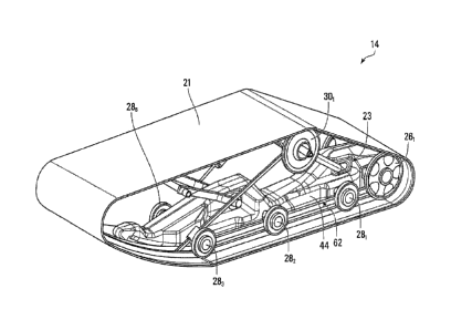
With additional reference to Figures 2 to 5, the track system 14 comprises a
track-
engaging assembly 24 and a track 21 disposed around the track-engaging
assembly
24. More particularly, in this embodiment, the track-engaging assembly 24
comprises a
frame 23 and a plurality of track-contacting wheels which includes a plurality
of drive
wheels 221, 222 and a plurality of idler wheels that includes rear idler
wheels 261, 262,
lower roller wheels 281-286, and upper roller wheels 301, 302. As it is
disposed between
the track 21 and the frame 11 of the snowmobile 10, the track-engaging
assembly 24
can be viewed as implementing a suspension for the snowmobile 10. The track
system
14 has a longitudinal direction and a first longitudinal end and a second
longitudinal end
11
CA 02996648 2018-02-26
WO 2017/031591 PCT/CA2016/051004
that define a length of the track system 14, a widthwise direction and a width
that is
defined by a width of the track 21, and a height direction that is normal to
its longitudinal
direction and its widthwise direction.
The track 21 engages the ground to provide traction to the snowmobile 10. A
length of
the track 21 allows the track 21 to be mounted around the track-engaging
assembly 24.
In view of its closed configuration without ends that allows it to be disposed
and moved
around the track-engaging assembly 24, the track 21 can be referred to as an
"endless"
track. With additional reference to Figures 6 to 9, the track 21 comprises an
inner side
25 for facing the track-engaging assembly 24 and a ground-engaging outer side
27 for
engaging the ground. A top run 65 of the track 21 extends between the
longitudinal
ends of the track system 14 and over the track-engaging assembly 24 (including
over
the wheels 221, 222, 261, 262, 281-286, 301, 302), and a bottom run 66 of the
track 21
extends between the longitudinal ends of the track system 14 and under the
track-
engaging assembly 24 (including under the wheels 221, 222, 281, 282, 281-286,
301, 302).
The bottom run 66 of the track 11 defines an area of contact 59 of the track
21 with the
ground which generates traction and bears a majority of a load on the track
system 14,
and which will be referred to as a "contact patch" of the track 21 with the
ground. The
track 21 has a longitudinal axis which defines a longitudinal direction of the
track 21
(i.e., a direction generally parallel to its longitudinal axis) and
transversal directions of
the track (i.e., directions transverse to its longitudinal axis), including a
widthwise
direction of the track (i.e., a lateral direction generally perpendicular to
its longitudinal
axis). The track 21 has a thickness direction normal to its longitudinal and
widthwise
directions.
The track 21 is elastomeric, i.e., comprises elastomeric material, to be
flexible around
the track-engaging assembly 24. The elastomeric material of the track 21 can
include
any polymeric material with suitable elasticity. In this embodiment, the
elastomeric
material of the track 21 includes rubber. Various rubber compounds may be used
and,
in some cases, different rubber compounds may be present in different areas of
the
12
CA 02996648 2018-02-26
WO 2017/031591 PCT/CA2016/051004
track 21. In other embodiments, the elastomeric material of the track 21 may
include
another elastomer in addition to or instead of rubber (e.g., polyurethane
elastomer).
More particularly, the track 21 comprises an endless body 35 underlying its
inner side
25 and ground-engaging outer side 27. In view of its underlying nature, the
body 35 will
be referred to as a "carcass". The carcass 35 is elastomeric in that it
comprises
elastomeric material 38 which allows the carcass 35 to elastically change in
shape and
thus the track 21 to flex as it is in motion around the track-engaging
assembly 24. The
elastomeric material 38 can be any polymeric material with suitable
elasticity. In this
embodiment, the elastomeric material 38 includes rubber. Various rubber
compounds
may be used and, in some cases, different rubber compounds may be present in
different areas of the carcass 35. In other embodiments, the elastomeric
material 38
may include another elastomer in addition to or instead of rubber (e.g.,
polyurethane
elastomer).
In this embodiment, the carcass 35 comprises a plurality of reinforcements 451-
45p
embedded in its rubber 38. These reinforcements 451-45p can take on various
forms.
For example, in this embodiment, a subset of the reinforcements 451-4-5p is a
plurality of
transversal stiffening rods 361-36N that extend transversally to the
longitudinal direction
of the track 21 to provide transversal rigidity to the track 21. More
particularly, in this
embodiment, the transversal stiffening rods 361-36N extend in the widthwise
direction of
the track 21. Each of the transversal stiffening rods 361-36N may have various
shapes
and be made of any suitably rigid material (e.g., metal, polymer or composite
material).
As another example, in this embodiment, the reinforcement 45; is a layer of
reinforcing
cables 371-37m that are adjacent to one another and extend generally in the
longitudinal
direction of the track 21 to enhance strength in tension of the track 21 along
its
longitudinal direction. In this case, each of the reinforcing cables 371-37m
is a cord
including a plurality of strands (e.g., textile fibers or metallic wires). In
other cases, each
of the reinforcing cables 371-37m may be another type of cable and may be made
of any
13
CA 02996648 2018-02-26
WO 2017/031591 PCT/CA2016/051004
material suitably flexible longitudinally (e.g., fibers or wires of metal,
plastic or composite
material). In some examples of implementation, respective ones of the
reinforcing
cables 371-37m may be constituted by a single continuous cable length wound
helically
around the track 21. In other examples of implementation, respective ones of
the
transversal cables 371-37m may be separate and independent from one another
(i.e.,
unconnected other than by rubber of the track 21).
As yet another example, in this embodiment, the reinforcement 45j is a layer
of
reinforcing fabric 43. The reinforcing fabric 43 comprises thin pliable
material made
usually by weaving, felting, knitting, interlacing, or otherwise crossing
natural or
synthetic elongated fabric elements, such as fibers, filaments, strands and/or
others,
such that some elongated fabric elements extend transversally to the
longitudinal
direction of the track 21 to have a reinforcing effect in a transversal
direction of the track
21. For instance, the reinforcing fabric 43 may comprise a ply of reinforcing
woven
fibers (e.g., nylon fibers or other synthetic fibers). For example, the
reinforcing fabric 43
may protect the transversal stiffening rods 361-36N, improve cohesion of the
track 21,
and counter its elongation.
The carcass 35 may be molded into shape in a molding process during which the
rubber 38 is cured. For example, in this embodiment, a mold may be used to
consolidate layers of rubber providing the rubber 38 of the carcass 35, the
reinforcing
cables 371-37m and the layer of reinforcing fabric 43.
In this embodiment, the track 21 is a one-piece "jointless" track such that
the carcass 35
is a one-piece jointless carcass. In other embodiments, the track 21 may be a
"jointed"
track (i.e., having at least one joint connecting adjacent parts of the track
21) such that
the carcass 35 is a jointed carcass (i.e., which has adjacent parts connected
by the at
least one joint). For example, in some embodiments, the track 21 may comprise
a
plurality of track sections interconnected to one another at a plurality of
joints, in which
case each of these track sections includes a respective part of the carcass
35. In other
14
CA 02996648 2018-02-26
WO 2017/031591 PCT/CA2016/051004
embodiments, the track 21 may be a one-piece track that can be closed like a
belt with
connectors at both of its longitudinal ends to form a joint.
The ground-engaging outer side 27 of the track 21 comprises a ground-engaging
outer
surface 31 of the carcass 35 and a plurality of traction projections 581-58T
that project
from the ground-engaging outer surface 31 to enhance traction on the ground.
The
traction projections 581-58T, which can be referred to as "traction lugs" or
"traction
profiles", may have any suitable shape (e.g., straight shapes, curved shapes,
shapes
with straight parts and curved parts, etc.).
In this embodiment, each of the traction projection 581-58T is an elastomeric
traction
projection in that it comprises elastomeric material 41. The elastomeric
material 41 can
be any polymeric material with suitable elasticity. More particularly, in this
embodiment,
the elastomeric material 41 includes rubber. Various rubber compounds may be
used
and, in some cases, different rubber compounds may be present in different
areas of
each of the traction projections 581-58T. In other embodiments, the
elastomeric material
41 may include another elastomer in addition to or instead of rubber (e.g.,
polyurethane
elastomer).
The traction projections 581-58T may be provided on the ground-engaging outer
side 27
in various ways. For example, in this embodiment, the traction projections 581-
58T are
provided on the ground-engaging outer side 27 by being molded with the carcass
35.
The inner side 25 of the track 21 comprises an inner surface 32 of the carcass
35 and a
plurality of inner projections 341-34D that project from the inner surface 32
and are
positioned to contact the track-engaging assembly 24 (e.g., at least some of
the wheels
221, 222, 261, 262, 281-286, 301, 302) to do at least one of driving (i.e.,
imparting motion
to) the track 21 and guiding the track 21. Since each of them is used to do at
least one
of driving the track 21 and guiding the track 21, the inner projections 341-
34D can be
referred to as "drive/guide projections" or "drive/guide lugs". In some cases,
a
drive/guide lug 34; may interact with a given one of the drive wheels 221, 222
to drive the
CA 02996648 2018-02-26
WO 2017/031591 PCT/CA2016/051004
track 21, in which case the drive/guide lug 34. is a drive lug. In other
cases, a
drive/guide lug 34. may interact with a given one of the idler wheels 261,
262, 281-282,
301, 302 and/or another part of the track-engaging assembly 24 to guide the
track 21 to
maintain proper track alignment and prevent de-tracking without being used to
drive the
track 21, in which case the drive/guide lug 34; is a guide lug. In yet other
cases, a
drive/guide lug 34; may both (i) interact with a given one of the drive wheels
221, 223 to
drive the track 21 and (ii) interact with a given one of the idler wheels 261,
262, 281-286,
301, 302 and/or another part of the track-engaging assembly 24 to guide the
track 21, in
which case the drive/guide lug 34i is both a drive lug and a guide lug.
In this embodiment, each of the drive/guide lugs 341-34D is an elastomeric
drive/guide
lug in that it comprises elastomeric material 42. The elastomeric material 42
can be any
polymeric material with suitable elasticity. More particularly, in this
embodiment, the
elastomeric material 42 includes rubber. Various rubber compounds may be used
and,
in some cases, different rubber compounds may be present in different areas of
each of
the drive/guide lugs 341-34D. In other embodiments, the elastomeric material
42 may
include another elastomer in addition to or instead of rubber (e.g.,
polyurethane
elastomer).
The drive/guide lugs 341-34D may be provided on the inner side 25 in various
ways. For
example, in this embodiment, the drive/guide lugs 341-34D are provided on the
inner
side 25 by being molded with the carcass 35.
In this embodiment, the carcass 35 has a thickness Tc which is relatively
small. The
thickness -lc of the carcass 35 is measured from the inner surface 32 to the
ground-
engaging outer surface 31 of the carcass 35 between longitudinally-adjacent
ones of the
traction projections 581-58T. For example, in some embodiments, the thickness
Tc of the
carcass 35 may be no more than 0.25 inches, in some cases no more than 0.22
inches,
in some cases no more than 0.20 inches, and in some cases even less (e.g., no
more
than 0.18 or 0.16 inches). The thickness Tc of the carcass 35 may have any
other
suitable value in other embodiments.
16
CA 02996648 2018-02-26
WO 2017/031591 PCT/CA2016/051004
The track-engaging assembly 24 is configured to drive and guide the track 21
around
the track-engaging assembly 24.
Each of the drive wheels 221, 222 is rotatable by an axle for driving the
track 21. That is,
power generated by the prime mover 15 and delivered over the powertrain 12 of
the
snowmobile 10 rotates the axle, which rotates the drive wheels 221, 222, which
impart
motion of the track 21. In this embodiment, each drive wheel 22; comprises a
drive
sprocket engaging some of the drive/guide lugs 341-34D of the inner side 25 of
the track
21 in order to drive the track 21. In other embodiments, the drive wheel 22;
may be
configured in various other ways. For example, in embodiments where the track
21
comprises drive holes, the drive wheel 22i may have teeth that enter these
holes in
order to drive the track 21. As yet another example, in some embodiments, the
drive
wheel 22; may frictionally engage the inner side 25 of the track 21 in order
to frictionally
drive the track 21. The drive wheels 221, 222 may be arranged in other
configurations
and/or the track system 14 may comprise more or less drive wheels (e.g., a
single drive
wheel, more than two drive wheels, etc.) in other embodiments.
The idler wheels 261, 262, 281-286, 301, 302 are not driven by power supplied
by the
prime mover 15, but are rather used to do at least one of guiding the track 21
as it is
driven by the drive wheels 221, 222, tensioning the track 21, and supporting
part of the
weight of the snowmobile 10 on the ground via the track 21. More particularly,
in this
embodiment, the rear idler wheels 261, 262 are trailing idler wheels that
maintain the
track 21 in tension, guide the track 21 as it wraps around them, and can help
to support
part of the weight of the snowmobile 10 on the ground via the track 21. The
lower roller
wheels 281-286 roll on the inner side 25 of the track 21 along the bottom run
66 of the
track 21 to apply the bottom run 66 on the ground. The upper roller wheels
301, 302 roll
on the inner side 25 of the track 21 along the top run 65 of the track 21 to
support and
guide the top run 65 as the track 21 moves. The idler wheels 261, 262, 281-
286, 301, 302
may be arranged in other configurations and/or the track assembly 14 may
comprise
more or less idler wheels in other embodiments.
17
CA 02996648 2018-02-26
WO 2017/031591 PCT/CA2016/051004
The frame 23 of the track system 14 supports various components of the track-
engaging assembly 24, including, in this embodiment, the idler wheels 261,
262, 281-286,
301, 302. More particularly, in this embodiment, the frame 23 comprises an
elongate
support 62 extending in the longitudinal direction of the track system 14
along the
bottom run 66 of the track 21 and frame members 491-49F extending upwardly
from the
elongate support 62.
The elongate support 62 comprises a rail 44 extending in the longitudinal
direction of
the track system 14 along the bottom run 66 of the track 21. In this example,
the idler
wheels 261, 262, 231-286 are mounted to the rail 44. In this embodiment, the
elongate
support 62 comprises a sliding surface 77 for sliding on the inner side 25 of
the track 21
along the bottom run 66 of the track 21. Thus, in this embodiment, the idler
wheels 261,
262, 281-286 and the sliding surface 77 of the elongate support 62 can contact
the
bottom run 66 of the track 21 to guide the track 21 and apply it onto the
ground for
traction.
The rail 44 is an elongate structure that is elongated in the longitudinal
direction of the
track system 14 and comprises an upper portion 61 and a lower portion 63
between the
upper portion 61 and the sliding surface 77, as shown in Figure 12. More
particularly,
the rail 44 comprises a top 80, lateral surfaces 821, 822 opposite one
another, and a
bottom 84. Axles of the idler wheels 261, 262, 281-286 are carried by the rail
44 such that
the idler wheels 261, 262, 281-286 are adjacent to respective ones of the
lateral surfaces
821, 822 of the rail 44,
In this example, the rail 44 is a sole rail of the track-engaging assembly 24,
which may
thus be viewed as implementing a "single-rail suspension". In other words, the
track-
engaging assembly 24 has a single rail (i.e., it is free of any other rail).
The rail 44 is
disposed in a central region of the track-engaging assembly 24. More
particularly, in this
embodiment, the rail 44 overlaps a centerline 85 of the track 21 (i.e., a line
that bisects
the width of the track 21) in the widthwise direction of the track system 14.
In this
18
CA 02996648 2018-02-26
WO 2017/031591 PCT/CA2016/051004
example, the sliding surface 77 overlaps the centerline 85 of the track 21.
This is in
contrast to a snowmobile's conventional track system which comprises a
plurality of
rails that are spaced apart from one another in the track system's widthwise
direction
such that they do not overlap a centerline of a track of the track system.
In some embodiments, as shown in Figures 2 to 6, in a cross-section of the
track
system 14 in the widthwise direction of the track system 14, the sliding
surface 77 of the
rail 44 and a bottom 55 of each of the roller wheels 281-286 between which the
rail 44 is
disposed may be aligned in the heightwise direction of the track system 14.
The inner
surface 32 of the track 21 in contact with the sliding surface 77 of the rail
44 and the
bottom 55 of each of the roller wheels 281-286 is thus substantially even
(i.e., flat) in the
widthwise direction of the track 21.
In other embodiments, as shown in Figures 28 to 36, in a cross-section of the
track
system 14 in the widthwise direction of the track system 14, the sliding
surface 77 of the
rail 44 and the bottom 55 of at least some of the roller wheels 281-284
between which
the rail 44 is disposed may be offset in the heightwise direction of the track
system 14
(in this example, the track-engaging assembly 24 comprises four roller wheels
281-284,
but could comprise more or less such roller wheels in other examples). There
is thus an
offset V1 between the sliding surface 77 of the rail 44 and the bottom 55 of
some of the
roller wheels 281-284 in the heightwise direction of the track system 14. The
inner
surface 32 of the track 21 in contact with the sliding surface 77 of the rail
44 and the
bottom 55 of each of the roller wheels 281-284 is therefore uneven (i.e., not
flat) in the
widthwise direction of the track 21. This may help to facilitate transitioning
of the
snowmobile from its upright position towards its leaning position.
More particularly, in this embodiment, the bottom 55 of at least some of the
roller
wheels 281-284 is located higher than the sliding surface 77 of the rail 44 in
the
heightwise direction of the track system 14. The inner surface 32 of the track
21 in
contact with the sliding surface 77 of the rail 44 and the bottom 55 of each
of the roller
wheels 281-284 is thus generally concave, curving or otherwise extending
upwardly from
19
CA 02996648 2018-02-26
WO 2017/031591 PCT/CA2016/051004
the sliding surface 77 of the rail 44 towards the bottom 55 of each of the
roller wheels
281-284.
The offset V, between the sliding surface 77 of the rail 44 and the bottom 55
of at least
some of the roller wheels 281-284 may have any suitable value. For example, in
some
embodiments, a ratio Vr/Ht of the offset V, between the sliding surface 77 of
the rail 44
and the bottom 55 of at least some of the roller wheels 281-284 over a height
Ht of the
track system 14 may be at least 0.01, in some cases at least 0.02; in some
cases at
least 0.03, and in some cases even more. As another example, in some
embodiments,
a ratio Vr/Dr of the offset V, between the sliding surface 77 of the rail 44
and the bottom
55 of at least some of the roller wheels 281-284 over a diameter Dr of a
roller wheel 28;
may be at least 0.05, in some cases at least 0.07, in some cases at least 0.1,
and in
some cases even more.
Furthermore, in the embodiment of Figures 42 to 50, the offset V, between the
sliding
surface 77 of the rail 44 and the bottom 55 of at least some of the roller
wheels 281-284
is implemented by a selected pair of laterally-adjacent ones of the roller
wheels roller
wheels 281-284 (roller wheels which are adjacent to one another in the
widthwise
direction of the track system 14). This selected pair of laterally-adjacent
ones of the
roller wheels roller wheels 281-284 are therefore not used for relieving
pressure on the
sliding surface 77 of the rail 44, but rather to provide a limit to the
leaning position of the
snowmobile 10 (e.g., when the snowmobile 10 is turning). In this example, the
selected
pair of laterally-adjacent ones of the roller wheels 281-284 which implements
the offset
V, is the roller wheels 282, 284 which constitute a frontmost pair of the
roller wheels 281-
284 (i.e., a pair of the roller wheels which is closest to a frontmost point
of the track
system 14 in its longitudinal direction). The other roller wheels 281, 283 do
no implement
the offset V, such that the sliding surface 77 of the rail 44 and the bottom
55 of each of
the roller wheels 281, 283 is generally aligned in the heightwise direction of
the track
system 14. Moreover, as shown in Figures 42, 44 and 45, in this embodiment,
the roller
wheels 282, 284 which implement the offset V, are spaced laterally from the
rail 44 more
CA 02996648 2018-02-26
WO 2017/031591 PCT/CA2016/051004
than the remainder of the roller wheels 281-284 (i.e., more than the roller
wheels 281,
283). =
In other examples, more than a single pair of the roller wheels 281-284 may
implement
the offset Vr. For instance, in cases where the track system 14 comprises more
than
four roller wheels (such as in the embodiment of Figures 2 to 6), two pairs of
the roller
wheels 281-286 may implement the offset Vr.
Furthermore, in this embodiment, the offset V,- between the sliding surface 77
of the rail
44 and the bottom 55 of at least some of the roller wheels 281-284 (i.e., the
roller wheels
282, 284) is implemented by making the diameter Dr of the at least some of the
roller
wheels 281-284 smaller than the diameter of the other roller wheels 281-284.
More
particularly, since an axle AX1 of the roller wheels 282, 284 is aligned with
an axle AX2
of the roller wheels 281, 283 in the heightwise direction of the track system
14, making
the diameter Dr of the roller wheels 282, 284 smaller than the diameter of the
roller
wheels 281, 283, implements the offset Vr between the sliding surface 77 of
the rail 44
and the bottom 55 of the roller wheels 282, 284.
The offset Vr between the sliding surface 77 of the rail 44 and the bottom 55
of the roller
wheels 282, 284 may be implemented differently in other embodiments. For
instance, in
some embodiments, rather than making the diameter Dr of the roller wheels 282,
284
smaller, the axle AX1 of the roller wheels 282, 284 may be supported at a
point higher in
the heightwise direction of the track system 14 than the axle AX2 of the
roller wheels
281, 283, such that the axle AX1 of the roller wheels 282, 284 is not aligned
with the axle
AX2 of the roller wheels 281, 283 in the heightwise direction of the track
system 14.
The frame members 491-49F extend upwardly from the elongate support 62 to hold
the
upper roller wheels 301, 302 such that the upper roller wheels 301, 302 roll
on the inner
side 25 of the track 21 along the top run 65 of the track 21.
21
CA 02996648 2018-02-26
WO 2017/031591 PCT/CA2016/051004
The frame 23 of the track system 14, including the rail 44, may comprise any
suitable
material imparting strength to the frame 23. In some cases, a single material
may make
up an entirety of the frame 23. In other cases, different materials may make
up different
portions of the frame 23 (e.g., one material making up the rail 44, another
material
making up another part of the frame 23 above the rail 44).
In this embodiment, the frame 23 comprises a nonmetallic material 86 making up
at
least a significant part (e.g., at least a majority) of the frame 23,
including the rail 44.
More particularly, in this embodiment, the nonmetallic material 86 is a
polymeric
material. In some cases, the polymeric material 86 may include a single
polymer. In
other cases, the polymeric material 86 may include a combination of polymers.
In yet
other cases, the polymeric material 86 may include a polymer-matrix composite
comprising a polymer matrix in which reinforcements are embedded (e.g., a
fiber-
reinforced polymer such as a carbon-fiber-reinforced polymer or glass-fiber-
reinforced
polymer). In this example of implementation, the polymeric material 86
includes high-
density polyethylene (e.g., high molecular weight high-density polyethylene).
Any other
suitable polymer may be used in other examples of implementation (e.g.,
polypropylene,
polyurethane, polycarbonate, low-density polyethylene, nylon, etc.).
In other embodiments, the frame 23 may comprise a metallic material (e.g.,
aluminum,
steel, etc.) or any other suitable material making up at least a significant
part (e.g., at
least a majority) of the frame 23, including the rail 44.
The sliding surface 77 of the elongate support 62 is configured to slide on
the inner side
25 of the track 21 along the bottom run 66 of the track 21 to guide the track
21 and
apply it onto the ground. In this embodiment, the sliding surface 77 can slide
against the
inner surface 32 of the carcass 35 and can contact respective ones of the
drive/guide
lugs 341-34D to guide the track 21 in motion. Also, in this embodiment, the
sliding
surface 77 is curved upwardly in a front region of the track system 14 to
guide the track
21 towards the drive wheels 22i, 222. In some cases, the track 21 may comprise
slide
members 391-39s that slide against the sliding surface 77 to reduce friction.
The slide
22
CA 02996648 2018-02-26
WO 2017/031591 PCT/CA2016/051004
members 391-39s, which can sometimes be referred to as "clips", may be mounted
via
holes 401-40K of the track 21. In other cases, the track 21 may be free of
such slide
members. The sliding surface 77 may be arranged in other configurations in
other
embodiments.
In this embodiment, the elongate support 62 comprises a slider 33 mounted to
the rail
44 and comprising the sliding surface 77. More particularly, in this
embodiment, the
slider 33 is mechanically interlocked with the rail 44. The slider 33
comprises an
interlocking portion 78 that is interlockable with an interlocking portion 88
of the rail 44 in
order to mechanically interlock the slider 33 and the rail 44. The
interlocking portion 88
of the rail 44 and the interlocking portion 78 of the slider 33 are
mechanically interlocked
by a given one of the interlocking portion 88 of the rail 44 and the
interlocking portion 78
of the slider 33 comprising an interlocking space (e.g., one or more holes,
one or more
recesses, and/or one or more other hollow areas) into which extends an
interlocking
part of the other one of the interlocking portion 88 of the rail 44 and the
interlocking
portion 78 of the slider 33.
More particularly, with additional reference to Figures 13 and 14, in this
embodiment,
the slider 33 comprises a base 70 extending in the widthwise direction of the
track
system 14, a pair of projections 72, 74 that project upwardly from the base
70, and a
mating portion 76 that is configured to mate with the rail 44 and defines the
interlocking
portion 78 of the slider 33. In this example, the interlocking portion 78 of
the slider 33
comprises an aperture for receiving the interlocking portion 88 of the rail
44.
In other embodiments, instead of or in addition to being mechanically
interlocked with
the rail 44, the slider 33 may be fastened to the rail 44. For example, in
some
embodiments, the slider 33 may be fastened to the rail 44 by one or more
mechanical
fasteners (e.g., bolts, screws, etc.), by an adhesive, and/or by any other
suitable
fastener.
23
CA 02996648 2018-02-26
WO 2017/031591 PCT/CA2016/051004
In some examples, the slider 33 may comprise a low-friction material which may
reduce
friction between its sliding surface 77 and the inner side 25 of the track 21.
For instance,
the slider 33 may comprise a polymeric material having a low coefficient of
friction with
the rubber of the track 21. For example, in some embodiments, the slider 33
may
comprise a thermoplastic material (e.g., a Hifax0 polypropylene). The slider
33 may
comprise any other suitable material in other embodiments. For instance, in
some
embodiments, the sliding surface 77 of the slider 33 may comprise a coating
(e.g., a
polytetrafluoroethylene (PTFE) coating) that reduces friction between it and
the inner
side 25 of the track 21, while a remainder of the slider 33 may comprise any
suitable
material (e.g., a metallic material, another polymeric material, etc.).
While in embodiments considered above the sliding surface 77 is part of the
slider 33
which is separate from and mounted to the rail 44, in other embodiments, the
sliding
surface 77 may be part of the rail 44. That is, the sliding surface 77 may be
integrally
formed (e.g., molded, cast, or machined) as part of the rail 44. For example,
the sliding
surface 77 may be part of the lower portion 63 of the rail 44.
In some embodiments, as shown in Figures 28, 29 and 34 to 36, the frame 23 may
comprise an elongate reinforcement 95 that extends along at least part of the
rail 44
and includes a reinforcing material 97 that is more rigid than the material 86
of the rail
44. This may lend reinforcement (e.g., rigidity) to the material 86 of the
rail 44 such as to
avoid overstressing the material 86 of the rail 44.
The reinforcing material 97 of the elongate reinforcement 95 may be
significantly stiffer
than the material 86 of the rail 44. For instance, a ratio of a modulus of
elasticity (i.e.,
Young's modulus) of the reinforcing material 97 of the elongate reinforcement
95 over a
modulus of elasticity of the material 86 of the rail 44 may be at least 1.5,
in some cases
at least 2, in some cases at least 5, in some cases at least 10, and in some
cases even
more.
24
CA 02996648 2018-02-26
WO 2017/031591 PCT/CA2016/051004
In this embodiment, the reinforcing material 97 of the elongate reinforcement
95 is
metallic material. For instance, the metallic material 97 may be an alloy
steel. Any other
suitable metal may be used (e.g., a titanium alloy). In other embodiments, the
reinforcing material 97 of the elongate reinforcement 95 may be a polymeric
material
that is more rigid than the material 86 of the rail 44 (e.g.,
polyvinylchloride (PVC),
polyethylene terephthalate (PET), a fiber-reinforced polymer).
In this embodiment, the elongate reinforcement 95 comprises a body 87
extending
along the longitudinal direction of the snowmobile 10 and a plurality of
locating openings
991-99N disposed in the body 87. The elongate reinforcement 95 extends along a
substantial portion of a length of the rail 44. For instance, the elongate
reinforcement 95
may extend along at least a majority (i.e., a majority or an entirety) of the
length of the
rail 44. The locating openings 991-99N are configured to reduce a weight of
the elongate
reinforcement 95 since the reinforcing material 97 may be denser than the
material 86
of the rail 44. Moreover, the locating openings 991-99N may allow to more
easily locate
the elongate reinforcement 95 relative to the rail 44 upon installing the
elongate
reinforcement 95. For instance, in this example of implementation, the rail 44
comprises
a plurality of protrusions 1011-101N that have a shape (e.g., rounded
rectangular) that
matches a shape of the locating openings 991-99N of the elongate reinforcement
95
such that a protrusion 101; of the plurality of protrusions 1011-101 N can be
inserted in a
respective opening 99; of the elongate reinforcement 95.
The elongate reinforcement 95 also comprises axle-receiving openings for
receiving
respective axles of the lower roller wheels 281-284. The axle-receiving
openings of the
elongate reinforcement 95 are aligned with axle-receiving openings of the rail
44 such
that the axles of the roller wheels (i.e., one axle for each pair of the lower
roller wheels
281-284 that is aligned in the longitudinal direction of the track system 14)
are received
in the axle-receiving openings of the elongate reinforcement 95 and the axle-
receiving
openings of the rails 44. In this example, as there are two pairs of the lower
roller
wheels 281-284 that are aligned in the longitudinal direction of the track
system 14, the
elongate reinforcement 95 comprises two axle-receiving openings.
CA 02996648 2018-02-26
WO 2017/031591 PCT/CA2016/051004
In order to secure the elongate reinforcement 95 to the rail 44, the elongate
reinforcement also comprises a plurality of fastener-receiving openings 1031-
103N for
receiving a respective fastener 205 therein. More particularly, the fastener-
receiving
openings 1031-103N are through holes such that the fasteners 205 extend
through the
fastener-receiving openings 1031-103N. In such embodiments, the rail 44
comprises a
plurality of fastener-engaging mounts 1061-106N for securedly engaging the
fasteners
205. In this example, each of the fastener-engaging mounts 1061-106N comprises
a
threaded insert to threadedly engage a corresponding one of the fasteners 205.
In this embodiment, the frame 23 comprises two elongate reinforcements 95, one
disposed on each lateral side of the rail 44. However, in some embodiments,
the frame
23 may comprise a single elongate reinforcement 95.
Moreover, as shown in Figures 29 and 30, in this example of implementation,
the track
system 14 comprises a tensioner 150 for tensioning the track 21. For instance,
in this
embodiment, the tensioner 150 comprises an actuator mounted at one end of the
frame
23 of the track system 14 and at another end to a member 155 which supports an
axle
of the rear idler wheels 261, 262. This allows the tensioner 150 to modify a
distance
between the rear idler wheels 261, 262 and the roller wheels 281-284 in the
longitudinal
direction of the track system 14. A similar tensioner could be implemented in
the
embodiment of the track system 14 depicted in Figures 2 to 6.
A lower part 90 of the track-engaging assembly 24 comprises an interface 92 of
the
track-engaging assembly 24 with the bottom run 66 of the track 21. The
interface 92 of
the track-engaging assembly 24 with the bottom run 66 of the track 21
comprises
surfaces of the track-engaging assembly 24 that are in contact with the bottom
run 66 of
the track 21, including, in this embodiment, a circumferential surface 94 of
each of the
idler wheels 261, 262, 281-286 and the sliding surface 77 of the elongate
support 62.
26
CA 02996648 2018-02-26
WO 2017/031591 PCT/CA2016/051004
The track system 14 is configured to enhance traction of the snowmobile 10 on
the
ground, including by maintaining proper engagement of the track 21 with the
ground
when the user leans (and possibly even stands) on a lateral side of the
snowmobile 10
to adjust a course of the snowmobile 10 and/or stabilize the snowmobile 10
over
uneven terrain and/or when the track system 14 is subject to other loading
that would
otherwise tend to reduce tractive forces generated by the track 21.
In this embodiment, with additional reference to Figures 15 and 16, the track
system 14
is configured such that, when the snowmobile 10 travels on the ground, at
least part of
the interface 92 of the track-engaging assembly 24 with the bottom run 66 of
the track
21 is movable relative to the frame 11 of the snowmobile 10 to change an
orientation of
one or more of the Surfaces of the track-engaging assembly 24 that are in
contact with
the bottom run 66 of the track 21 (i.e., the circumferential surface 94 of
each of the idler
wheels 261, 262, 281-286 and the sliding surface 77 of the elongate support
62) relative
to the frame 11 of the snowmobile 10. This relative movement may help to
maintain
proper engagement of the track 21 with the ground during maneuvers of the
snowmobile 10 and/or under other loading conditions which would otherwise tend
to
reduce tractive forces generated by the track 21. For example, this relative
movement
may occur in response to leaning of the snowmobile 10 relative to the ground
(e.g.,
when the user banks the snowmobile 10 to turn). Alternatively or additionally,
this
relative movement may occur in response to an unevenness of the ground 14
(e.g., a
bump, obstacle or other change in ground level) in the widthwise direction of
the track
system 14.
More particularly, in this embodiment, the track system 14 is configured such
that, when
the snowmobile 10 travels on the ground, one or more of the surfaces of the
track-
engaging assembly 24 that are in contact with the bottom run 66 of the track
21 (i.e., the
circumferential surface 94 of each of the idler wheels 261, 262, 281-286 and
the sliding
surface 77 of the elongate support 62) are rotatable relative to the frame 11
of the
snowmobile 10 about a roll axis RA substantially parallel to the longitudinal
direction of
the track system 14. That is, a surface of the track-engaging assembly 24 that
is in
27
CA 02996648 2018-02-26
WO 2017/031591 PCT/CA2016/051004
contact with the bottom run 66 of the track 21 is movable relative to the
frame 11 of the
snowmobile 10 such that movement of that surface of the track-engaging
assembly 24
relative to the frame 11 of the snowmobile 10 includes a rotation of that
surface of the
track-engaging assembly 24 relative to the frame 11 of the snowmobile 10 about
the roll
axis RA.
This is achieved, in this embodiment, by the track system 14 being configured
such that,
when the snowmobile 10 travels on the ground, an upper part 91 of the track-
engaging
assembly 24 is movable relative to the lower part 90 of the track-engaging
assembly 24
to change an orientation of the upper part 91 of the track-engaging assembly
24 relative
to the lower part 90 of the track engaging assembly 24. In this example, the
upper part
91 of the track-engaging assembly 24 is rotatable relative to the lower part
90 of the
track-engaging assembly 24 about the roll axis RA. That is, the upper part 91
of the
track-engaging assembly 24 is movable relative to the lower part 90 of the
track-
engaging assembly 24 such that movement of the upper part 91 of the track-
engaging
assembly 24 relative to the lower part 90 of the track-engaging assembly 24
includes a
rotation of the upper part 91 of the track-engaging assembly 24 relative to
the lower part
90 of the track-engaging assembly 24 about the roll axis RA.
Notably, in this embodiment, the track system 14 is configured such that, when
the
snowmobile 10 travels on the ground, the sliding surface 77 of the elongate
support 62
is movable relative to the frame 11 of the snowmobile 10 to change an
orientation of the
sliding surface 77 relative to the frame 11 of the snowmobile 10. Thus, in
this example,
the sliding surface 77 is rotatable relative to the frame 11 of the snowmobile
10 about
the roll axis RA. That is, the sliding surface 77 is movable relative to the
frame 11 of the
snowmobile 10 such that movement of the sliding surface 77 relative to the
frame 11 of
the snowmobile 10 includes a rotation of the sliding surface 77 relative to
the frame 11
of the snowmobile 10 about the roll axis RA.
In this embodiment, the track system 14 is configured such that, when the
snowmobile
travels on the ground, the upper portion 61 of the rail 44 is movable relative
to the
28
CA 02996648 2018-02-26
WO 2017/031591 PCT/CA2016/051004
sliding surface 77 to change an orientation of the upper portion 61 of the
rail 44 relative
to the sliding surface 77. Thus, in this example, the upper portion 61 of the
rail 44 is
rotatable relative to the sliding surface 77 about the roll axis RA. That is,
the upper
portion 61 of the rail 44 is movable relative to the sliding surface 77 such
that movement
of the upper portion 61 of the rail 44 relative to the sliding surface 77
includes a rotation
of the upper portion 61 of the rail 44 relative to the sliding surface 77
about the roll axis
RA.
Movement of the upper portion 61 of the rail 44 relative to the sliding
surface 77 may be
implemented in any suitable way. Examples of how this may be achieved in
various
embodiments are discussed below.
I. Resilient deformation
In some embodiments, as shown in Figures 15 and 16, the track-engaging
assembly 24
comprises a resiliently deformable area 96 that is resiliently deformable to
allow
movement of the upper part 91 of the track-engaging assembly 24 relative to
the lower
part 90 of the track-engaging assembly 24.
More particularly, in this embodiment, the lower portion 63 of the rail 44 is
resiliently
deformable to allow movement of the upper portion 61 of the rail 44 relative
to the
sliding surface 77. The resiliently deformable area 96 is thus part of the
lower portion 63
of the rail 44 in this example.
The resiliently deformable area 96 may be implemented in various ways. For
instance,
the resiliently deformable area 96 may have a relatively low stiffness. More
specifically,
in this embodiment, the stiffness of the lower portion 63 of the rail 44 may
be less than a
stiffness of the upper portion 61 of the rail 44 (i.e., the lower portion 63
of the rail 44 is
more flexible than the upper portion 61 of the rail 44).
29
CA 02996648 2018-02-26
WO 2017/031591 PCT/CA2016/051004
In this embodiment, the lower portion 63 of the rail 44 comprises a resilient
material 98
which provides compliance to the lower portion 63 of the rail 44. In this
case, the
resilient material 98 is the polymeric material 86 making up the rail 44,
including the
lower portion 63 of the rail 44. More specifically, the resilient material 98
of the lower
portion 63 of the rail 44 is operable to deform from a first configuration to
a second
configuration in response to a load and recover the first configuration in
response to
removal of the load.
More particularly, in this embodiment, a modulus of elasticity (i.e., Young's
modulus) of
the resilient material 98 may be no more than 10 GPa, in some cases no more
than 5
GPa, in some cases no more than 1 GPa, and in some cases even less (e.g., no
more
than 0.5 GPa). The modulus of elasticity of the resilient material 98 may have
any other
suitable value in other embodiments.
For instance, in some examples, the stiffness of the lower portion 63 of the
rail 44 may
be calculated, based on a minimal cross-section of the lower portion 63 of the
rail 44
taken parallel to the longitudinal direction of the track system, as a product
of (i) the
modulus of elasticity of the material 98 of the lower portion 53 of the rail
44 at that
minimal cross-section and (i) an area moment of inertia (i.e., a second moment
of area)
of the minimal cross-section of the lower portion 63 of the rail 44 with
respect to an axis
parallel to the longitudinal direction of the track system. For example, in
some
embodiments, the stiffness of the lower portion 63 of the rail 44 may be no
more than
1.0E4 GPa/mm4, in some cases no more than 5.0E3 GPa/mm4, in some cases no more
than 1.0E3 GPa/mm4, and in some cases even less (e.g., no more than 5.0E2
GPa/mm4). The stiffness of the lower portion 63 of the rail 44 may have any
other
suitable value in other embodiments.
In this embodiment, the rail 44 is a hollow structure. That is, the rail 44
comprises a
hollow interior 68. More particularly, in this embodiment, the hollow interior
68 occupies
a majority of a volume of the rail 44. The hollow interior 68 therefore
occupies at least
50%, in some cases at least 65%, in some cases at least 80%, and in some cases
an
CA 02996648 2018-02-26
WO 2017/031591 PCT/CA2016/051004
even greater proportion (e.g., at least 90% or 95%) of the volume of the rail
44. In other
embodiments, the hollow interior 68 may occupy a smaller proportion of the
volume of
the rail 44. This hollowness of the rail 44 may help to facilitate resilient
deformation of
the rail 44 for movement of the upper portion 61 of the rail 44 relative to
the sliding
surface 77 as well as to reduce a weight of the track system 14. In this case,
as further
discussed later, the hollowness of the rail 44 is created during molding of
the rail 44.
The hollow interior 68 is defined by a wall 29 of the rail 44. In this
embodiment, the wall
29 encloses the hollow interior 68 such that the hollow interior 68 is closed.
This
prevents mud, rocks, debris and/or other undesirable ground matter from
entering into
the hollow interior 68 of the rail 44.
The wall 29 has a thickness suitable for providing sufficient rigidity to the
rail 44. This
depends on the material 86 making up the rail 44 and on loads to which the
rail 44 is
expected to be subjected to. For example, in some embodiments, the thickness
of the
wall 29 may be at least 1 mm, in some cases at least 3 mm, in some cases at
least 5
mm, and in some cases at least 8 mm. For instance, in this example of
implementation
in which the wall 29 includes high-density polyethylene, the thickness of the
wall 29 may
be between 2 mm and 8 mm. In cases in which the thickness of the wall 29
varies such
that it takes on different values in different regions of the rail 44, the
thickness of the
wall 29 may be taken as its minimum thickness. In other cases, the thickness
of the wall
29 may be generally constant over an entirety of the rail 44.
The rail 44 may be manufactured in any suitable manner. In this embodiment,
the rail 44
is molded into shape in a mold such that it is a molded structure. In
particular, in this
case, the hollowness and the upper and lower portions 61, 63 of the rail 44
are realized
during molding of the rail 44.
More specifically, in this embodiment, the rail 44 is blow-molded into shape
such that it
is a blow-molded structure. For instance, Figure 17 is a flowchart
illustrating an example
of a blow-molding process used to mold the rail 44.
31
CA 02996648 2018-02-26
WO 2017/031591 PCT/CA2016/051004
At step 200, the polymeric material 86 that will make up the rail 44 is
provided. For
instance, in some cases, the polymeric material 86 may be provided as a
preform (also
sometimes called "parison"), which is essentially a hot hollow tube of
polymeric material.
In other cases, the polymeric material 86 may be provided as one or more hot
sheets.
At step 220, pressurized gas (e.g., compressed air) is used to expand the
polymeric
material 86 against a mold. The mold has an internal shape generally
corresponding to
the shape of the rail 44 such that, as it is expanded against the mold, the
polymeric
material 86 is shaped into the rail 44. In this embodiment, this creates a
shape of the rail
44, including its hollow interior space 68. Pressure is held until the
polymeric material 86
cools and hardens.
At step 240, once the polymeric material 86 has cooled and hardened, the rail
44 is
retrieved from the mold.
At optional step 260, one or more additional operations (e.g., trimming) may
be
performed on the rail 44 which has been molded.
The rail 44 is thus constructed in this embodiment to enhance the performance
of the
track system 14. For example, owing to its polymeric material 86 that provides
compliance and to its configuration, the resiliently deformable area 96 of the
lower
portion 63 of the rail 44 allows for movement of the upper portion 61 of the
rail 44
relative to the sliding surface 77 when the snowmobile 10 travels. Also, due
to the
hollowness of the rail 44, the frame 23 may be voluminous yet lightweight,
thus helping
to contain the weight of the track system 14. As another example, by being
voluminous,
the rail 44 occupies space within the track system 14 which would otherwise be
available for unwanted ground matter (i.e., snow, ice and/or other debris) to
accumulate
in, and, therefore, helps to reduce a potential for unwanted ground matter
accumulation
in the track system 14.
32
CA 02996648 2018-02-26
WO 2017/031591 PCT/CA2016/051004
Although it is configured in a certain manner in this embodiment, the rail 44
may be
configured in various other manners in other embodiments.
For example, while the rail 44 has a certain shape in this embodiment, the
rail 44 may
have any other suitable shape in other embodiments.
As another example, although in this embodiment the rail 44 is blow-molded, in
other
embodiments, the rail 44 may be manufactured using other manufacturing
processes.
For example, in some embodiments, the rail 44 may be manufactured by a
rotational
molding (sometimes also referred to as "rotomolding") process in which a
heated mold
is filled with material and then rotated (e.g., about two perpendicular axes)
to cause the
material to disperse and stick to a wall of the mold. As another example, in
some
embodiments, the rail 44 may be manufactured by individually forming two or
more
pieces and then assembling these pieces together (e.g., individually forming
two halves
of the rail 44 and then assembling these two halves together; individually
forming the
upper and lower portions 61, 63 of the rail 44 and then assembling these
pieces
together; etc.). Such individual forming of two or more pieces may be effected
by
individually molding (e.g., by an injection or other molding process),
extruding, or
otherwise forming these two or more pieces. Such assembling may be effected by
welding (e.g., sonic welding), adhesive bonding, using one or more fasteners
(e.g.,
bolts, screws, nails, etc.), or any other suitable technique.
In this embodiment, the resiliently deformable area 96 defines the roll axis
RA about
which the upper portion 61 of the rail 44 is rotatable relative to the sliding
surface 77 of
the elongate support 62. In other words, the upper portion 61 of the rail 44
is rotatable
about the resiliently deformable area 96 and more specifically about the roll
axis RA
which is substantially parallel to the longitudinal direction of the track
system 14. The
weight of the track system 14 is generally balanced in its widthwise direction
about a
central axis CA bisecting a width of the rail 44 and extending through the
roll axis RA
such that the central axis CA is normal to the sliding surface 77 of the
elongate support
62.
33
CA 02996648 2018-02-26
WO 2017/031591 PCT/CA2016/051004
More particularly, in this embodiment, the rail 44 is operable to resiliently
deform from a
neutral configuration to a biased configuration and vice-versa. More
specifically, with
additional reference to Figure 15, the rail 44 adopts the neutral
configuration when the
track system 14 is unloaded (i.e., when the rail 44 is not subjected to any
load external
to the track system 14) or centrally-loaded (i.e., the rail 44 is subjected to
a net load F
external to the track system 14 that is generally aligned with the central
axis CA). For
example, the rail 44 may adopt the neutral configuration when a center of
gravity of the
user of the snowmobile 10 is generally aligned with respect to the central
axis CA (e.g.,
when the user is sitting up straight on the seat 18 of the snowmobile 10).
In the neutral configuration of the rail 44, a lateral axis LA of the upper
portion 61 of the
rail 44 (i.e., an axis extending in a widthwise direction of the upper portion
61 of the rail
44) is generally orthogonal to the central axis CA of the rail 44. In other
words, in the
neutral configuration, the lateral axis LA is substantially parallel to the
sliding surface 77
of the elongate support 62.
As shown in Figure 16, the rail 44 transitions to the biased configuration in
response to
the net load F being offset from the central axis CA of the rail 44. More
specifically, as
the net load F is offset from the central axis CA, a bending moment is
generated at the
roll axis RA which causes the rail 44 to deform and adopt the biased
configuration. For
example, the rail 44 may adopt the biased configuration when the center of
gravity of
the user is offset from the central axis CA (e.g., when the user is leaning
towards a
lateral side of the snowmobile 10).
When the rail 44 transitions to the biased configuration, the orientation of
the upper
portion 61 of the rail 44 is changed relative to the sliding surface 77 of the
elongate
support 62. More specifically, the rail 44 transitions to the biased
configuration through a
rotation of the upper portion 61 of the rail 44 relative to the sliding
surface 77 about the
roll axis RA by a roll angle (1) (e.g., measured between the sliding surface
77 and the
lateral axis LA of the upper portion 61 of the rail 44). The roll angle (1)
may depend on
34
CA 02996648 2018-02-26
WO 2017/031591 PCT/CA2016/051004
the magnitude of the net load F and its distance from the central axis CA of
the rail 44
amongst other factors (e.g., elasticity of the resilient material 98 of the
deformable area
96). For example, in some embodiments, the roll angle (1) may be at least 5 ,
in some
cases at least 100, in some cases at least 15 , in some cases at least 20 , in
some
cases at least 25 , and in some cases even more.
The rotational motion of the upper portion 61 of the rail 44 about the roll
axis RA may
enable the sliding surface 77 to substantially remain in contact with the
inner side 25 of
the track 21 to apply the bottom run 66 of the track 21 onto the ground on
which the
snowmobile 10 travels. This may enhance traction between the track 21 and the
ground.
Once the net load F is substantially aligned with the central axis CA of the
rail 44 (or the
rail 44 is no longer subjected to the net load F), the rail 44 transitions
from the biased
configuration to the neutral configuration. That is, the upper portion 61 of
the rail 44
rotates about the roll axis RA such that the lateral axis LA of the upper
portion 61 of the
rail 44 is substantially parallel with the sliding surface 77.
Although the rail 44 is illustrated as being biased towards one lateral side
of the track
system 14, it will be appreciated that the rail 44 may be biased towards an
opposite
lateral side of the track system 14 when the net load F is applied on an
opposite side of
the central axis CA. Moreover, although the net load F is depicted in the
drawings as
being applied at a location within a widthwise extent of the rail 44, this is
merely to
simplify the illustrations. In many cases, the net load F may be applied at a
location in
the widthwise direction of the track system 14 beyond the widthwise extent of
the rail
44.
The upper portion 61 of the rail 44 may be configured to move relative to the
sliding
surface 77 of the elongate support 62 in any other suitable way in other
embodiments.
CA 02996648 2018-02-26
WO 2017/031591 PCT/CA2016/051004
For instance, in some embodiments, the slider 33 of the elongate support 62
may be
configured to resiliently deform rather than the rail 44. More specifically,
with additional
reference to Figures 18 to 20, the slider 33 of the elongate support 62 may
comprise a
resiliently deformable area 196 that is resiliently deformable to allow
movement of the
mating portion 76 of the slider 33 relative to the base 70 of the slider 33.
In view of its
mating engagement with the rail 44, the resiliently deformable slider 33
allows
movement of the rail 44, including the upper portion 61 of the rail 44,
relative to the
sliding surface 77 of the slider 33.
The resiliently deformable area 196 of the slider 33 may be implemented in any
suitable
way, including in a manner similar to that described above in respect of the
resiliently
deformable area 96 of the rail 44. For instance, the resiliently deformable
area 196 may
have a relatively low stiffness. More specifically, in some embodiments, the
stiffness of
the slider 33 may be less than the stiffness of the upper portion 61 of the
rail 44 (i.e., the
slider 33 may be more flexible than the upper portion 61 of the rail 44). For
example, in
some embodiments, the stiffness of the slider 33 may be no more than 1.0E4
GPaimm4,
in some cases no more than 5.0E3 GPa/mm4, in some cases no more than 1.0E3
GPa/mm4, and in some cases even less (e.g., no more than 5.0E2 GPa/mm4). The
stiffness of the slider 33 may have any other suitable value in other
embodiments.
More particularly, in this embodiment, the slider 33 comprises a resilient
material 198
which provides compliance to the slider 33. More specifically, the resilient
material 198
of the slider 33 is operable to deform from a first configuration to a second
configuration
in response to a load and recover the first configuration in response to
removal of the
load. For instance, in some embodiments, a modulus of elasticity of the
resilient
material 198 may be smaller than the modulus of elasticity of the polymeric
material 86
of the rail 44. For example, in some embodiments, a modulus of elasticity of
the resilient
material 198 may no more than 10 GPa, in some cases no more than 5 GPa , in
some
cases no more than 1 GPa, and in some cases even less (e.g., no more than 0.5
GPa).
The modulus of elasticity of the resilient material 198 may have any other
suitable value
in other embodiments.
36
CA 02996648 2018-02-26
WO 2017/031591 PCT/CA2016/051004
In this example of implementation, the resilient material 198 of the slider 33
comprises a
polymeric material. For instance, the resilient material 198 of the slider 33
may be a
thermoplastic material (e.g., a Hifaxe polypropylene). The resilient material
198 of the
slider 33 may be any other suitable material in other examples of
implementation.
In this embodiment, the resiliently deformable area 196 of the slider 33
defines the roll
axis RA about which the mating portion 76 of the slider 33, and consequently
the upper
portion 61 of the rail 44, is rotatable. In other words, the upper portion 61
of the rail 44 is
rotatable about the resiliently deformable area 196 and more specifically
about the roll
axis RA which is substantially parallel to the longitudinal direction of the
track system 14.
The weight of the track system 14 is generally balanced in its widthwise
direction about
the central axis CA bisecting the width of the rail 44 and extending through
the roll axis
RA such that the central axis CA is normal to the sliding surface 77 of
elongate support
62.
In this embodiment, the slider 33 is operable to resiliently deform from a
neutral
configuration to a biased configuration and vice-versa. As shown in Figure 19,
the slider
33 adopts the neutral configuration when the track system 14 is unloaded
(i.e., the slider
33 is not subjected to any load external to the track system 14) or centrally-
loaded (i.e.,
the slider 33 is subjected to the net load F that is generally aligned with
the central axis
CA of the rail 44). In the neutral configuration of the slider 33, the rail 44
is in a first
position in which the lateral axis LA of its upper portion 61 is substantially
parallel with
the sliding surface 77 of the slider 33.
With additional reference to Figure 20, the slider 33 transitions to the
biased
configuration in response to the net load F being offset from the central axis
CA of the
rail 44. More specifically, as the net load F is offset from the central axis
CA, a bending
moment is generated at the roll axis RA which causes the slider 33 to deform
and adopt
the biased configuration.
37
CA 02996648 2018-02-26
WO 2017/031591 PCT/CA2016/051004
When the slider 33 transitions to the biased configuration, the rail 44 (which
is mateably
engaged with the slider 33) is moved to a second position. More specifically,
the rail 44,
including the upper portion 61 of the rail 44, is rotated about the roll axis
RA relative to
the sliding surface 77 by a roll angle 0 (e.g., measured from the sliding
surface 77 of the
slider 33 to the lateral axis LA of the rail 44). For example, in some
embodiments, the
roll angle 0 may be at least 5 , in some cases at least 100, in some cases at
least 15 ,
in some cases at least 20 , in some cases at least 25 , and in some cases even
more.
The rotational motion of the upper portion 61 of the rail 44 about the roll
axis RA may
allow the slider 33 and its sliding surface 77 to substantially remain in
place to apply the
bottom run 66 of the track 21 onto the ground on which the snowmobile 10
travels. This
may enhance traction between the track 21 and the ground.
Once the net load F is aligned with the central axis CA of the slider 33 (or
the slider 33 is
no longer subjected to the net load F), the slider 33 again transitions from
the biased
configuration to the neutral configuration which causes the rail 44 to
transition from the
second position back to the first position. Although the slider 33 is
illustrated as being
biased towards one lateral side of the track system 14, it will be appreciated
that the
slider 33 may be biased towards an opposite lateral side of the track system
14 when
the net load F is applied on an opposite side of the central axis CA.
In some embodiments, the rail 44 may not be resiliently deformable since,
through its
compliance, the slider 133 causes the rail 44 to rotate about the roll axis
RA. Thus, in
this embodiment, the rail 44 may comprise a non-resilient material, including
metallic
material, polymeric material, or any other suitable material. Moreover, the
rail 44 may be
manufactured in any suitable way.
In other embodiments, both the rail 44 and the slider 33 may be resiliently
deformable
(i.e., both the resiliently deformable area 96 of the rail 44 and the
resiliently deformable
area 196 of the slider 33 may be provided) so that the movement of the upper
portion
38
CA 02996648 2018-02-26
WO 2017/031591 PCT/CA2016/051004
61 of the rail 44 relative to the sliding surface 77 involves resilient
deformations of the
rail 44 and the slider 33.
II. Movable mechanical joint
In some embodiments, as shown in Figures 23 to 26, the track-engaging assembly
24
comprises a movable mechanical joint 300 between the upper part 91 of the
track-
engaging assembly 24 and the lower part 90 of the track-engaging assembly 24
to allow
movement of the upper part 91 of the track-engaging assembly 24 relative to
the lower
part 90 of the track-engaging assembly 24.
More particularly, in this embodiment, the movable mechanical joint 300 is
between the
upper portion 61 of the rail 44 and the sliding surface 77 to allow movement
of the upper
portion 61 of the rail 44 relative to the sliding surface 77. In this example,
the movable
mechanical joint 300 is between the rail 44 and the slider 33.
In this embodiment, the movable mechanical joint 300 comprises a pivot 310 to
allow
pivoting of the upper portion 61 of the rail 44 relative to the sliding
surface 77.
The pivot 310 may be implemented in any suitable way. For instance, in this
embodiment, the pivot 310 comprises a connection between the lower portion 63
of the
rail 44 and the slider 33. More particularly, in this embodiment, the lower
portion 63 of
the rail 44 comprises a first engaging member 312 that is configured to engage
a
second engaging member 314 of the slider 33 such that the first engaging
member 312
is movable relative to the second engaging member 314. The connection between
the
first and second engaging members 312, 314 defines the roll axis RA about
which the
upper portion 61 of the rail 44 is pivotable.
As shown in Figures 23 and 24, in this embodiment, the first engaging member
312
comprises a housing 316 and the second engaging member 314 comprises a
circular
stud 318, the housing 316 being configured to receive the circular stud 318.
The
39
CA 02996648 2018-02-26
WO 2017/031591 PCT/CA2016/051004
housing 316 of the first engaging member 312 comprises a bearing 320 (e.g., a
polymer
bearing) defining a cavity 322 configured to securely receive the circular
stud 318. The
circular stud 318 is thus rotatable within the cavity 322 against the bearing
320.
In this embodiment, the roll axis RA is located at a center of the circular
stud 318 and is
substantially parallel to the longitudinal direction of the track system 14. A
central axis
CA' of the pivot 310 extends through the roll axis RA and is normal to the
sliding surface
77 of the slider 33.
The upper portion 61 of the rail 44 is rotatable from a neutral position to an
inclined
position and vice-versa. More specifically, with additional reference to
Figure 25, the
upper portion 61 of the rail 44 adopts the neutral position when the track
system 14 is
centrally-loaded (i.e., the rail 44 is subjected to a net load F external to
the track system
14 that is generally aligned with the central axis CA'). For example, the
upper portion 61
of the rail 44 is in the neutral position when a center of gravity of the user
of the
snowmobile 10 is generally aligned with respect to the central axis CA' (e.g.,
when the
user is sitting up straight on the seat 18 of the snowmobile 10).
In the neutral position, the lateral axis LA of the upper portion 61 of the
rail 44 is
generally orthogonal to the central axis CA'. In other words, in the neutral
position, the
lateral axis LA is substantially parallel to the sliding surface 77 of the
slider 33.
As shown in Figure 26, the upper portion 61 of the rail 44 transitions to the
inclined
position in response to the net load F being offset from the central axis CA'.
More
specifically, as the net load F is offset from the central axis CA', a moment
is generated
at the roll axis RA which causes the upper portion 61 of the rail 44 to move
to the
inclined position. For example, the upper portion 61 of the rail 44 may adopt
the inclined
position when the center of gravity of the user is offset from the central
axis CA' (e.g.,
when the user is leaning towards the side of the snowmobile 10).
CA 02996648 2018-02-26
WO 2017/031591 PCT/CA2016/051004
When the upper portion 61 of the rail 44 moves to the inclined position, the
orientation
of the upper portion 61 of the rail 44 is changed relative to the sliding
surface 77 of the
elongate support 62. More specifically, the upper portion 61 of the rail 44
transitions to
the inclined position through a rotation of the upper portion 61 of the rail
44 relative to
the sliding surface 77 about the roll axis RA by a roll angle a (e.g.,
measured from the
sliding surface 77 of the slide rail 33 to the lateral axis LA of the upper
portion 61 of the
rail 44). The roll angle a may depend on the magnitude of the net load F and
its
distance from the central axis CA' amongst other factors. For example, in some
embodiments, the roll angle a may be at least 50, in some cases at least 100,
in some
cases at least 15 , in some cases at least 20 , in some cases at least 25 ,
and in some
cases even more.
The rotational motion of the upper portion 61 of the rail 44 about the roll
axis RA may
enable the slider 33 and its sliding surface 77 to substantially remain in
contact with the
inner side 25 of the track 21 to apply the bottom run 66 of the track 21 onto
the ground
matter on which the snowmobile 10 travels. This may enhance traction between
the
track 21 and the ground.
Once the net load F is substantially aligned with the central axis CA', the
upper portion
61 of the rail 44 moves from the inclined position to the neutral position.
That is, the
upper portion 61 of the rail 44 rotates about the roll axis RA such that the
lateral axis LA
of the rail 44 substantially parallel with the sliding surface 77 of the
slider 33.
Although the upper portion 61 of the rail 44 is illustrated as being moved
towards one
lateral side of the track system 14, it will be appreciated that the upper
portion 61 of the
rail 44 may be moved towards an opposite lateral side of the track system 14
when the
net load F is applied on an opposite side of the central axis CA'. Moreover,
although the
net load F is depicted in the drawings as being applied at a location within a
widthwise
extent of the rail 44, this is merely to simplify the illustrations. In many
cases, the net
load F may be applied at a location in the widthwise direction of the track
system 14
beyond the widthwise extent of the rail 44.
41
CA 02996648 2018-02-26
WO 2017/031591 PCT/CA2016/051004
In this embodiment, the rail 44 and the slider 33 may comprise any suitable
material
(e.g., metallic material, polymeric material, etc.) since neither the rail 44
nor the slider
33 needs to be resiliently deformable. In some embodiments, the rail 44 and/or
the
slider 33 may comprise resilient material as discussed above to be resiliently
deformable, in addition to motion allowed by the movable mechanical joint 300.
In some embodiments, with additional reference to Figure 27, the movable
mechanical
joint 300 of the track-engaging assembly 24 may comprise a resilient device
350 for
biasing the orientation of the upper portion 61 of the rail 44 relative to the
sliding surface
77 towards a predetermined orientation. The resilient device 350 comprises a
spring
352. The spring 352 may be a coil spring, a torsion spring, a leaf spring, an
elastomeric
spring (e.g., a rubber spring), a fluid spring (e.g., an air spring), or any
other object that
is operable to change in configuration from a first configuration to a second
configuration in response to a load and recover the first configuration in
response to
removal of the load.
For example, in this embodiment, the spring 352 of the resilient device 350
may
comprise a torsion spring mounted on a pin 354 which is connected to the
slider 33 (not
shown in Figure 27). The spring 352 comprises first and second ends 356, 358
which
are respectively connected to the slider 33 and the rail 44. More
specifically, the first
end 356 of the spring 352 may be connected to the base 70 of the slider 33
while the
second end 358 of the spring 352 may be connected to the first engaging member
312
of the lower portion 63 of the rail 44 (e.g., to the housing 316).
Thus, when the upper portion 61 of the rail 44 moves to its inclined position
(as
illustrated in Figure 26), the first engaging member 312 of the rail 44
rotates about the
roll axis RA and moves the second end 358 of the spring 352 such as to cause a
bending moment at the spring 352. The spring 352 resists this movement by
applying a
force proportional to a stiffness of the spring 352 on the first engaging
member 312 via
the second end 358. The force applied by the spring 352 on the first engaging
member
42
CA 02996648 2018-02-26
WO 2017/031591 PCT/CA2016/051004
312 tends to bias the orientation of the upper portion 61 of the rail 44
relative to the
sliding surface 77 towards a predetermined orientation which in this case
coincides with
the neutral position of the upper portion 61 of the rail 44 (i.e., when the
lateral axis LA is
substantially parallel to the sliding surface 77 of the slider 33).
The resilient device 350 may thus aid the user of the snowmobile 10 in
centering his/her
body mass relative to the snowmobile 10 such that his/her center of gravity is
substantially aligned with the central axis CA'. More specifically, the
stiffness of the
spring 352 may not be sufficient to stop the user from changing the
orientation of the
upper portion 61 of the rail 44 when he/she offsets his/her center of gravity
from the
central axis CA', but the spring 352 may facilitate the movement of the upper
portion 61
of the rail 44 towards its neutral position (i.e., when the lateral axis LA is
substantially
parallel to the sliding surface 77 of the slider 33) when the user wishes to
reorient the
upper portion 61 of the rail 44 towards the neutral position.
The resilient device 350 may comprise another spring similar to the spring 352
on an
opposite lateral side of the rail 44 to have a similar effect on movement of
the upper
portion 61 of the rail 44 relative to the sliding surface 77 towards the
opposite side of the
track system 14.
Movement of the upper portion 61 of the rail 44 relative to the sliding
surface 77 may be
implemented in any other suitable way in other embodiments.
Although embodiments considered above relate to movement of the upper portion
61 of
the rail 44 relative to the sliding surface 77, principles disclosed herein
may be applied
to other components of the interface 92 of the track-engaging assembly 24 with
the
bottom run 66 of the track 21 such that, when the snowmobile 10 travels on the
ground,
an orientation of one or more other surfaces of the track-engaging assembly 24
that are
in contact with the bottom run 66 of the track 21, such as the circumferential
surface 94
of each of one or more of the idler wheels 261, 262, 281-286, relative to the
frame 11 of
the snowmobile 10 is variable.
43
CA 02996648 2018-02-26
WO 2017/031591 PCT/CA2016/051004
For example, in some embodiments, the circumferential surface 94 of each of
one or
more of the idler wheels 261, 262, 281-286 may be rotatable relative to the
frame of the
11 of the snowmobile 10 about the roll axis RA due to compliance of the
polymeric
material 86 of the rail 44 (e.g., which has been blow-molded) that provides
some "give"
allowing a change in orientation of the axle of each of these one or more
idler wheels
relative to the frame 11 of the snowmobile 10 (i.e., (i.e., deformation of the
polymeric
material 86 around the idler wheel's axle). For instance, in some embodiments,
the
polymeric material 86 of the rail 44 may deform to allow an angular
displacement of the
axle of the idler wheel relative to the frame 11 of the snowmobile 10 of at
least 50, in
some cases at least 10 , in some cases at least 15 , in some cases at least 20
, and in
some cases even more. In some examples, this may allow a linear displacement
of the
axle of the idler wheel relative to the frame 11 of the snowmobile 10 of at
least 5 mm, in
some cases at least 10 mm, and in some cases even more.
The track system 14 may be implemented in any other suitable way in other
embodiments.
For example, in some embodiments, as shown in Figures 21 and 22, the elongate
support 62 of the frame 23 of the track system 14 may comprise a plurality of
rails 1441,
1442 that are spaced apart in the widthwise direction of the track system 14
and a
plurality of sliding surfaces 1771, 1772 that are spaced apart in the
widthwise direction of
the track system 14. In this embodiment, when the snowmobile 10 travels on the
ground, an upper portion 161 of each rail 144 is movable relative to a sliding
surface
177; below it in order to change an orientation of the upper portion 161 of
the rail 144
relative to the sliding surface 177i, similarly to what was discussed
previously.
In this example, the rail 144 is nnateably engaged with a corresponding slider
133; of a
plurality of sliders 1331, 1332 via an interlocking portion of the rail 144.
Each slider 133;
comprises a sliding surface 177; of the plurality of sliding surfaces 1771,
1772. In other
44
CA 02996648 2018-02-26
WO 2017/031591 PCT/CA2016/051004
embodiments, the sliders 1331, 1332 may be made integrally with the rails
1441, 1442
such that the sliding surfaces 1771, 1772 are part of the rails 1441, 1442.
In this embodiment, the plurality of rails 1441, 1442 are linked via
structural members
(not shown) such that the plurality of rails 1441, 1442, together, support
axles of the idler
wheels 261, 262, 281-286.
In this embodiment, a resiliently deformable area 296 of each rail 144,
defines the roll
axis RA about which the upper portion 161 of the rail 144, is rotatable. In
other words,
the upper portion 161 of the rail 144, is rotatable about the resiliently
deformable area
296 of the rail 144, and more specifically about the roll axis RA which is
substantially
parallel to the longitudinal direction of the track system 14. The resiliently
deformable
area 296 may be implemented in a manner similar to that described above in
respect of
the resiliently deformable area 96. The weight of the track system 14 is
balanced in its
widthwise direction between normal axes NAi, NA2 of respective ones of the
rails 1441,
1442, each normal axis NA, extending through a corresponding roll axis RA such
that the
normal axis NA i is normal to a corresponding sliding surface 177,.
Each rail 144, is operable to resiliently deform from a neutral configuration
to a biased
configuration and vice-versa. More specifically, with additional reference to
Figure 21,
the rail 144; adopts the neutral configuration when the track system 14 is
unloaded (i.e.,
when the elongate support 62 is not subjected to any load external to the
track system
14) or centrally-loaded (i.e., the elongate support 62 is subjected to a net
load F
external to the track system 14 and applied at a location between the normal
axes NMI
NA2 or coinciding with one of the normal axes NAi , NA2 of the rails 1441,
1442). For
example, the rail 144, may adopt the neutral configuration when the center of
gravity of
the user of the snowmobile 10 is located between the normal axes NA1, NA2 of
the rails
1441, 1442 (e.g., when the user is sitting up straight on the seat 18 of the
snowmobile
10).
CA 02996648 2018-02-26
WO 2017/031591 PCT/CA2016/051004
In the neutral configuration, a lateral axis LA' of the upper portion 161 of
each of the rails
1441, 1442 (i.e., an axis extending in a widthwise direction of the upper
portion 161 of
each of the rails 1441, 1442) is generally orthogonal to the normal axes NA-1,
NA2 of the
rails 1441, 1442. In other words, in the neutral configuration, the lateral
axis LA' is
substantially parallel to the sliding surfaces 1771, 1772 of the sliders 1331,
1332.
As shown Figure 22, at least one rail 144; of the plurality of rails 1441,
1442 transitions to
the biased configuration in response to the net load F being applied at a
location not
between the normal axes NAi, NA2. More specifically, as the net load F is
moved to a
location not between the normal axes NAi, NA2, a bending moment is generated
at the
roll axis RA of the rail 144; closest to the location of the net load F which
causes the rail
144; to deform and adopt the biased configuration. For example, the rail 144;
adopts the
biased configuration when the center of gravity of the user is applied at a
location not
between the normal axes NAi, NA2 of the elongate support 62 (e.g., when the
user is
leaning towards the side of the snowmobile 10).
When the rail 144; transitions to the biased configuration, an orientation of
the upper
portion 161 of the rail 144; is changed relative to the sliding surface 177;
of the
corresponding slider 133. More specifically, the rail 144; transitions to the
biased
configuration through a rotation of the upper portion 161 of the rail 144;
relative to the
sliding surface 177 about the roll axis RA by a roll angle 13 (e.g., measured
between the
sliding surface 177; and the lateral axis LA' of the upper portion 161 of the
rail 144). The
roll angle p may depend on the magnitude of the net load F and its distance
from the
normal axis NA., of the rail 144; amongst other factors (e.g., elasticity of a
resilient
material of the rail 1440. For example, in some embodiments, the roll angle 13
may be at
1east5 , in some cases at least 10 , in some cases at least 15 , in some cases
at least
200, in some cases at least 25 , and in some cases even more.
In the example shown in Figure 22, the rail 1441 resiliently deforms since the
net load F
is applied at a location not between the normal axes NAi, NA2 and closest to
the rail
1441. As illustrated, while the motion of the lateral axis LA' of the elongate
support 62
46
CA 02996648 2018-02-26
WO 2017/031591 PCT/CA2016/051004
relative to the sliding surface 1771 may cause the sliding surface 1772 to
lose contact
with the inner side 25 of the track 21, it may also enable the slider 1331 and
its sliding
surface 1771 to substantially remain in contact with the inner side 25 of the
track 21 to
apply the bottom run 66 of the track 21 onto the ground matter on which the
snowmobile
travels. This may enhance traction between the track 21 and the ground
compared
to prior art track systems comprising a plurality of rails.
Once the net load F is applied at a location between the normal axes NAi , NA2
(or the
elongate support 62 is no longer subjected to the net load F), the rail 1441
transitions
from the biased configuration to the neutral configuration.
Although the rail 1441 is illustrated as being biased in Figure 22, it will be
appreciated
that the rail 1442 may equally be biased when the net load F is applied on an
opposite
lateral side of the track system 14 at a location not between the normal axes
NA1, NA2.
Moreover, although the net load F is depicted in the drawings as being applied
at a
location within a widthwise extent of the elongate support 62, this is merely
to simplify
the illustrations. In many cases, the net load F may be applied at a location
in the
widthwise direction of the track system 14 beyond the widthwise extent of the
elongate
support 62.
In a variant, each slider 133; may be configured similarly to the resiliently
deformable
slider 33 described above. For instance, in such a variant, the slider 133;
may be
resiliently deformable to transition from a neutral configuration to a biased
configuration
thus enabling the corresponding rail 144; to rotate about a roll axis of the
slider 133. In
such cases, the rails 1441, 1442 may comprise any suitable material (e.g.,
metallic
material, polymeric material, etc.).
While in this embodiment the track system 14 is part of the snowmobile 10, in
other
embodiments, a track system constructed according to principles discussed
herein may
be used as part of other types of off-road vehicles.
47
CA 02996648 2018-02-26
WO 2017/031591 PCT/CA2016/051004
For example, in some embodiments, as shown in Figures 38 to 46 a track system
514
including a track 521 constructed according to principles discussed herein may
be used
as part of a snow bike 510. The snow bike 510 comprises a frame 511, a
powertrain
512, a ski system 517, the track system 514, a seat 518, and a user interface
520 which
enables a user to ride, steer and otherwise control the snow bike 510. The
snow bike
510 has a length, a width, and a height that respectively define a
longitudinal direction,
a widthwise direction, and a heightwise direction of the snow bike 510.
In this embodiment, with additional reference to Figure 47, the snow bike 510
is a
motorcycle equipped with the ski system 517 mounted in place of a front wheel
602 of
the motorcycle and the track system 514 mounted in place of a rear wheel 604
of the
motorcycle. In this example, the track system 514 also replaces a rear
suspension unit
525 (e.g., a shock absorber 559 and a swing arm 561) of the motorcycle.
Basically, in
this embodiment, the ski system 517 and the track system 514 are part of a
conversion
system 513 that converts the motorcycle into a skied and tracked vehicle for
travelling
on snow.
As further discussed below, in this embodiment, the ski system 517 and the
track
system 514 are designed to enhance travel of the snow bike 510 on the ground,
including to facilitate banking of the snow bike 510 (e.g., to turn, on a side
hill, etc.),
steering of the snow bike 510 by turning the ski system 14, and/or moving on
harder
snow (e.g., packed snow).
The powertrain 512 is configured for generating motive power and transmitting
motive
power to the track system 514 to propel the snow bike 510 on the ground. To
that end,
the powertrain 512 comprises a prime mover 515, which is a source of motive
power
that comprises one or more motors (e.g., an internal combustion engine, an
electric
motor, etc.). For example, in this embodiment, the prime mover 515 comprises
an
internal combustion engine. In other embodiments, the prime mover 515 may
comprise
another type of motor (e.g., an electric motor) or a combination of different
types of
motor (e.g., an internal combustion engine and an electric motor). The prime
mover 515
48
CA 02996648 2018-02-26
WO 2017/031591 PCT/CA2016/051004
is in a driving relationship with the track system 514. That is, the
powertrain 512
transmits motive power from the prime mover 515 to the track system 514 in
order to
drive (i.e., impart motion to) the track system 514.
The seat 518 accommodates the user of the snow bike 510. In this case, the
seat 518 is
a straddle seat and the snow bike 510 is usable by a single person such that
the seat
518 accommodates only that person driving the snow bike 510. In other cases,
the seat
518 may be another type of seat, and/or the snow bike 510 may be usable by two
individuals, namely one person driving the snow bike 510 and a passenger, such
that
the seat 518 may accommodate both of these individuals (e.g., behind one
another).
The user interface 520 allows the user to interact with the snow bike 510 to
control the
snow bike 510. More particularly, in this embodiment, the user interface 520
comprises
an accelerator, a brake control, and a steering device comprising handlebars
522 that
are operated by the user to control motion of the snow bike 510 on the ground.
The user
interface 520 also comprises an instrument panel (e.g., a dashboard) which
provides
indicators (e.g., a speedometer indicator, a tachometer indicator, etc.) to
convey
information to the user.
The ski system 517 is disposed in a front 524 of the snow bike 510 to engage
the
ground and is turnable to steer the snow bike 510. To that end, the ski system
14 is
turnable about a steering axis 526 of the snow bike 10. As shown in Figure 38,
the ski
system 14 comprises a ski 528 to slide on the snow and a ski mount 530 that
connects
the ski 28 to a front steerable member 532 of the snow bike 510. In this
embodiment
where the snow bike 510 is a motorcycle and the ski system 14 replaces the
front wheel
602 of the motorcycle, the front steerable member 532 comprises a front fork
534 of the
snow bike 510 that would otherwise carry the front wheel 602.
The ski 528 is a sole ski of the snow bike 510. That is, the snow bike 510 has
no other
ski. Notably, the ski 528 is disposed in a center of the snow bike 510 in a
widthwise
direction of the snow bike 510. In this embodiment in which the snow bike 510
is a
49
CA 02996648 2018-02-26
WO 2017/031591 PCT/CA2016/051004
motocycle and the ski system 517 replaces the front wheel 602 of the
motorcycle, the
ski 528 contacts the ground where the front wheel 602 would contact the
ground.
In this embodiment, the track system 514 comprises a mounting arrangement 519
to
mount the track system 514 to the motorcycle 510. More particularly, in this
embodiment, the mounting arrangement 519 comprises a transmission 527 for
transmitting power from the powertrain 512 of the snow bike 510 to drive
wheels 5221,
5222 of a track-engaging assembly 524 of the track system 514, and a subframe
529 for
interconnecting a frame 523 of the track-engaging assemb1y524 and the frame
511 of
the snow bike 510.
In this example, with reference to Figures the transmission 527 comprises an
input
transmission portion 531 and an output transmission portion 533. The input
transmission portion 531 comprises wheels 532, 535 and an elongated
transmission link
530 for transmitting motion between the wheel 532 and the wheel 535. The wheel
532
of the input transmission portion 531 is configured to be rotated by power
from the
powertrain 512 of the snow bike 510 (e.g., mounted to a driven axle of the
powertrain
512). The output transmission portion 533 comprises wheels 538, 540 and an
elongated
transmission link 536 for transmitting motion between the wheel 538 and the
wheel 540.
The wheel 540 is configured to rotate the drive wheels 5221, 5222 of the track
system
514 (e.g., mounted to an axle to which the drive wheels 5221, 5222 are
mounted). The
wheel 535 of the input transmission portion 531 and the wheel 538 of the
output
transmission portion 533 are mounted on a floating axle 537 which defines an
axis of
rotation 539 that is common to both of the wheels 535, 538. In this case, each
of the
elongate transmission links 530, 536 is a chain and each of the wheels 532,
535, 538,
540 is a sprocket. The elongate transmission links 530, 536 and/or the wheels
532, 535,
538, 540 may be implemented in any other suitable way in other embodiments
(e.g.,
transmission belts).
In this embodiment, the mounting arrangement 519 of the track system 514
comprises a
tensioner 542 for adjusting a tension in each of the chains 530, 536. In this
example, the
CA 02996648 2018-02-26
WO 2017/031591 PCT/CA2016/051004
tensioner 542 is configured to simultaneously adjust the tension in each of
the chains
530, 536.
More particularly, in this embodiment, the tensioner 542 comprises an actuator
545
movable in response to a command to adjust the tension in each of the chains
530, 536.
In this example, the actuator 545 is manually operable by a user such that the
command can be provided by the user by manually operating the actuator 545.
The actuator 545 may be implemented in any suitable way. For example, in this
embodiment, the actuator 545 comprises a lever 546 carrying the sprockets 535,
538
and movable relative to the frame 523 of the track system 514 to change a
position of
the sprockets 535, 538 relative to the sprockets 532, 540. More particularly,
the lever
546 comprises a proximal end portion 541 from which the lever 546 may be
grasped
and a distal end portion 543 receiving the floating axle 537 (e.g., via a
bearing) which
supports the sprockets 535, 538. The lever 546 also comprises a first opening
547
between the proximal and distal end portions 541, 543 and a second opening 549
at the
proximal end portion 541. The first opening 547 receives therein a fixed axle
551 of the
subframe 529 that extends in the widthwise direction of the track system 514.
The
second opening 549 is configured to receive a fastener 553 for affixing the
lever 546 to
the subframe 529.
The floating axle 537 is selectively movable via actuation of the lever 546.
In particular,
when the fastener 553 is loosened from engagement with a corresponding
fastening
element (e.g., a nut), the lever 546 is pivotable about a pivot 548 defined by
the fixed
axle 551 and having a pivot axis 557. This allows the floating axle 537, which
is
supported at the distal portion 543 of the lever 546, to pivot about the pivot
axis 557. In
this example, the second opening 549 of the lever 232 is a slot (e.g., an
arcuate slot) in
order to allow the proximal end portion 541 of the lever 546 to be secured to
the
subframe 529 once the lever 546 has been pivoted.
51
CA 02996648 2018-02-26
WO 2017/031591 PCT/CA2016/051004
The floating axle 537 may also be displaced linearly by the lever 546. More
specifically,
the first opening 547 of the lever 546 can be a slot extending in a
longitudinal direction
of the lever 546 such that the lever 546 can be displaced linearly through the
engagement of the fixed axle 551 with the slot 547 of the lever 546. In this
case, an
opening in an elongated lateral member of the subframe 529 which receives
therein the
fastener 553 may be configured as a slot that extends in the longitudinal
direction of the
track system 514.
The pivoting and linear motions of the floating axle 537 allows selectively
moving the
floating axle 537 and therefore the sprockets 535, 538 closer to or further
from the
sprockets 532, 540. This movement of the sprockets 535, 538 induces a change
in the
tension of each of the chains 530, 536 that can be effected simultaneously.
In other embodiments, the actuator 545 may comprise any other type of
actLiator. For
instance, in some embodiments, the actuator 545 may comprise an
electromechanical
actuator (e.g., a linear actuator) or a fluidic actuator (e.g., a hydraulic or
pneumatic
actuator). Also, in other embodiments, the command for moving the actuator 545
may
be generated automatically (e.g., by a sensor sensing that the tension is
inappropriate
and is to be changed).
The subframe 529 of the mounting arrangement 519 comprises a plurality of
links 550,
552 between the frame 523 of the track system 514 and the frame 511 of the
motorcycle 510. In this embodiment, the link 550 pivotally interconnects the
frame 523
of the track system 514 and the frame 511 of the motorcycle 510 (to allow
vertical
movement of the frame 523 of the track system 514 relative to the frame 511 of
the
motorcycle 510. In this case, the link 550 pivotally interconnects the frame
523 of the
track system 514 and the frame 511 of he motorcycle 510 at a pivot axis 565 of
the
frame 511 of the motorcycle 510 at which the swing arm 561 of the motorcycle
510
would be connected. The link 552 extends between the frame 523 of the track
system
514 and a mount 555 on the frame 511 of the motorcycle 510 at which the shock
absorber 559 of the motorcycle's rear suspension unit 525 would be connected.
52
CA 02996648 2018-02-26
WO 2017/031591 PCT/CA2016/051004
In this embodiment, the link 552 is resiliently deformable (i.e., changeable
in
configuration) to allow the frame 523 of the track system 514 to move relative
to the
frame 511 of the motorcycle 510. This may help to absorb shocks and/or
otherwise
improve ride comfort. More particularly, the link 552 comprises a resilient
element 554
that is configured to resiliently deform (i.e., change in configuration) from
a first
configuration to a second configuration in response to a load and recover the
first
configuration in response to removal of the load. For example, in this
embodiment, the
resilient element 554 comprises an elastomeric material 556 (e.g., rubber). In
other
embodiments, the resilient element 554 comprises a spring, such as a coil
spring (e.g.,
a metallic or polymeric coil spring), an elastomeric spring (e.g., a rubber
spring), a leaf
spring, a fluid spring (i.e., a spring including a liquid or gas contained in
a container
such as a cylinder or a bellows and variably compressed by a piston or other
structure,
such as an air spring or other gas spring or a piston-cylinder arrangement),
or any other
elastic object that changes in configuration under load and recovers its
initial
configuration when the load is removed.
The frame 523 of the track system 514 may be configured in any suitable way.
In this
embodiment, the frame 523 of the track system 514 comprises an elongate
support 562
that has a single rail 544 (e.g., a single-rail suspension, as discussed
above) disposed
in a central region of the track-engaging assembly 524 where it overlaps a
centerline
585 of the track 521. The frame 523, including the rail 544, may be
constructed
according to principles discussed herein, including as discussed above in
respect of the
frame 23 and the rail 44 of the track system 14, notably such that, when the
snow bike
510 travels on the ground, a sliding surface 577 of the elongate support 562
is movable
relative to the frame 511 of the snow bike 510 to change an orientation of the
sliding
surface 577 relative to the frame 511 of the snow bike 510. In this example,
the rail 544,
including its sliding surface 577, is aligned (i.e., overlaps) with the ski
528 of the ski
system 517 in the widthwise direction of the snow bike 510.
53
CA 02996648 2018-02-26
WO 2017/031591 PCT/CA2016/051004
In this embodiment, the subframe 529 comprises a pair of elongated lateral
members
5581, 5582 that are elongated in a longitudinal direction of the track system
514 and
disposed outside of lateral edges 5661, 5662 of the track 521. As shown in
Figure 43
which portrays a top cross-sectional view of an elongated lateral member 558,,
in this
embodiment, the elongated lateral member 558, comprises a first portion 560
and a
second portion 563 that projects laterally outwardly from the first portion
560 to define a
recess 564 to receive the sprockets 538, 540 and the chain 536. The first
portion 560 of
the elongated lateral member 558, is thus closer to the track 521 than the
second
portion 563 of that elongated lateral member 558, in the widthwise direction
of the track
system 514. This reduces an envelope of the track system 514, which may
provide
more space for the user (e.g., around footrests of the motorcycle 510).
In this embodiment, each of the elongated lateral members 5581, 5582 is plate-
like with
its first portion 560 being generally planar. The elongated lateral members
5581, 5582
may have any other suitable shape in other embodiments. Moreover, in some
embodiments, the subframe 529 may comprise additional elongated lateral
members
5671, 5672 configured to be connected with the elongated lateral members 5581,
5582 in
order to cover the transmission 527.
In this embodiment, as shown in Figure 44, a frame member 5691 of the frame
523 of
the track system 514 (corresponding generally to the frame member 491 of the
frame 23
of the track system 14) extends upwardly and forwardly from the rail 544 to
the
subframe 529 of the mounting arrangement 519 to interconnect the rail 544 and
the
subframe 529 such that the rail 544 is movable relative to the subframe 529.
In this
embodiment, the rail 544 is pivotable relative to the subframe 529. More
particularly, in
this embodiment, the frame member 5691 is pivotally mounted to the subframe
529 at a
pivot 570 and pivotally mounted to the rail 544 at a pivot 571.
In some embodiments, a pivot axis 572 of the pivot 570 between the frame
member
5691 of the frame 523 and the subframe 529 may be located so as to optimally
balance
54
CA 02996648 2018-02-26
WO 2017/031591 PCT/CA2016/051004
loading (e.g., weight) between the track system 514 in the rear of the snow
bike 510
and the ski system 517 in the front of the snow bike 10.
For example, in this embodiment where the track system 514 replaces the rear
wheel
604 of the motorcycle 510 that would be carried by the swing arm 561, a
distance
between the pivot axis 565 of the motorcycle 510 and the pivot axis 258 of the
pivot 253
between the frame member 5691 and the subframe 529 may be related to (e.g.,
less
than) a length Lsa of the swing arm 561 of the motorcycle 510 that has been
removed.
For instance, with additional reference to Figure 45, in some embodiments, a
ratio of (i)
the distance between the pivot axis 565 of the motorcycle 510 and the pivot
axis 572 of
the pivot 570 between the frame member 5691 and the subframe 529 over (ii) the
length
Lsa of the swing arm 561 of the motorcycle 510 that has been removed may be no
more
than 0.8, in some cases no more than 0.7, in some cases no more than 0.6, and
in
some cases even less (e.g., 0.5).
This positioning of the pivot axis 572 of the pivot 570 may allow a better
distribution of
the weight of the snow bike 510 between the ski system 517 and the track
system 514
compared to conventional track system designs. For example, this may allow a
decreased weight being applied at the ski system 517 compared to similar
vehicles
equipped with conventional track designs. In some cases, it may enhance
performance
of the snow bike 10 on flat and rough terrain and/or result in a better
balance of stability
and hill climbing ability of the snow bike 510.
The track 521 may be relatively wide. This may provide enhanced floatation in
deep
snow and/or enhance traction in wet snow. Moreover, this may allow the track
system
514 to be mounted to larger or heavier motorcycles. Also, in this example, the
track 521
may be relatively wide because the track system 514 does not rely on the
motorcycle's
rear suspension unit and is therefore less constrained. For example, in some
embodiments, with reference to Figures 47 and 49 a ratio of a width Wt of the
track 521
over a width Wõ,,, of a tire 606 of the rear wheel 604 of the motorcycle that
is replaced by
the track system 514 may be greater than two, in some cases at least 2.1, in
some
CA 02996648 2018-02-26
WO 2017/031591 PCT/CA2016/051004
cases at least 2.2, in some cases at least 2.3, in some cases at least 2.4,
and in some
cases even more (e.g., at least 2.5) This ratio may have any other value in
other
embodiments. As another example, in some embodiments, a ratio of the width Wt
of the
track 521 over a width Ws of a sliding surface 577 of an elongate support 562
of the
track-engaging assembly 524 may be greater than 4.5, in some cases at least 5,
in
some cases at least 5.5, in some cases at least 6, in some cases at least 6.5
and in
some cases even more. This ratio may have any other value in other
embodiments. For
instance, in some embodiments, the width Wt of the track 521 may be greater
than 10
inches, in some cases at least 11 inches, in some cases at least 12 inches,
and in some
cases even more (e.g., at least 12.5 inches).
Although in this embodiment the snow bike 510 is a motorcycle in which the ski
system
517 and the track system 514 are part of the conversion system 513 that is
mounted in
place of the front wheel 602 and the rear wheel 604 of the motorcycle, in
other
embodiments, the snow bike 510 may be designed and originally built with the
ski
system 517 and the track system 514 by a manufacturer of the snow bike 510,
i.e., the
snow bike 10 may never have been a motorcycle.
As another example, in some embodiments, as shown in Figures 50 and 51, a
track
system 414 including a track 421 constructed according to principles discussed
herein
may be used as part of an all-terrain vehicle (ATV) 410. More specifically, in
this
example, the track system 414 is one of a plurality of track systems 4141-4144
of the
ATV 410 that engages the ground to provide traction to the ATV 410. In this
example,
front ones of the track systems 4141-4144 provide front traction to the ATV
410 while
rear ones of the track systems 4141-4144 provide rear traction to the ATV 410.
Moreover, in this example, each track system 414; is mounted in place of a
ground-
engaging wheel 415 that may otherwise be mounted at a position of the track
system
414 to propel the ATV 410 on the ground. For example, as shown in Figures 52
and 53,
the ATV 410 may be propelled on the ground by four ground-engaging wheels 4151-
4154 having tires instead of by the track systems 4141-4144. Basically, in
this
56
CA 02996648 2018-02-26
WO 2017/031591 PCT/CA2016/051004
embodiment, the track systems 4141-4144 may be used to convert the ATV 410
from a
wheeled vehicle into a tracked vehicle, thereby enhancing its traction and
floatation on
the ground.
With additional reference to Figures 54 to 58, in this embodiment, each track
system
414; comprises a track-engaging assembly 422 and a track 421 disposed around
the
track-engaging assembly 422. In this example, the track-engaging assembly 422
comprises a frame 423 and a plurality of track-contacting wheels which
includes a drive
wheel 442 and a plurality of idler wheels 4501-45012. The track system 414;
has a front
longitudinal end 457 and a rear longitudinal end 459 that define a length of
the track
system 414i. The frame 423 supports the plurality of idler wheels 4501-45012.
The track 421 is mounted around the track-engaging assembly 422 and engages
the
ground to provide traction to the ATV 410. Referring additionally to Figures
59 and 60,
the track 421 comprises an inner side 445 facing the wheels 442, 4501-45012
and
defining an inner area of the track 421 in which these wheels are located. The
track 421
also comprises a ground-engaging outer side 447 opposite the inner side 445
for
engaging the ground on which the ATV 410 travels. Lateral edges 4631, 4632 of
the
track 421 define the track's width. The track 421 has a top run 465 which
extends
between the longitudinal ends 457, 459 of the track system 414; and over the
drive
wheel 442, and a bottom run 466 which extends between the longitudinal ends
457, 459
of the track system 4.14; and under the idler wheels 4501-45012. The bottom
run 466 of
the track 421 defines an area of contact 458 of the track 421 with the ground
which
generates traction and bears a majority of a load on the track system 414i,
and which
will be referred to as a "contact patch" of the track 421 with the ground.
The track 421 comprises an elastomeric belt-shaped body 436 underlying its
inner side
445 and its ground-engaging outer side 447. In view of its underlying nature,
the body
436 can be referred to as a "carcass". The carcass 436 comprises elastomeric
material
437 which allows the track 421 to flex around the wheels 442, 4501-45012.
57
CA 02996648 2018-02-26
WO 2017/031591 PCT/CA2016/051004
As shown in Figure 60, in this embodiment, the carcass 436 comprises a
plurality of
reinforcements embedded in its elastomeric material 437. One example of a
reinforcement is a layer of reinforcing cables 4381-438c that are adjacent to
one another
and that extend in the longitudinal direction of the track 421 to enhance
strength in
tension of the track 421 along its longitudinal direction. In some cases, a
reinforcing
cable may be a cord or wire rope including a plurality of strands or wires. In
other cases,
a reinforcing cable may be another type of cable and may be made of any
material
suitably flexible longitudinally (e.g., fibers or wires of metal, plastic or
composite
material). Another example of a reinforcement is a layer of reinforcing fabric
440.
Reinforcing fabric comprises pliable material made usually by weaving,
felting, or
knitting natural or synthetic fibers. For instance, a layer of reinforcing
fabric may
comprise a ply of reinforcing woven fibers (e.g., nylon fibers or other
synthetic fibers).
Various other types of reinforcements may be provided in the carcass 436 in
other
embodiments.
The carcass 436 may be molded into shape in the track's molding process during
which
its elastomeric material 437 is cured. For example, in this embodiment, layers
of
elastomeric material providing the elastomeric material 437 of the carcass
436, the
reinforcing cables 4381-438c and the layer of reinforcing fabric 40 may be
placed into
the mold and consolidated during molding.
In this embodiment, the inner side 445 of the track 421 comprises an inner
surface 432
of the carcass 436 and a plurality of wheel-contacting projections 4481-448N
that project
from the inner surface 432 to contact at least some of the wheels 442, 4501-
45010 and
that are used to do at least one of driving (i.e., imparting motion to) the
track 421 and
guiding the track 421. In that sense, the wheel-contacting projections 4481-
448N can be
referred to as "drive/guide projections", meaning that each drive/guide
projection is used
to do at least one of driving the track 421 and guiding the track 421. Also,
such
drive/guide projections are sometimes referred to as "drive/guide lugs" and
will thus be
referred to as such herein. More particularly, in this embodiment, the
drive/guide lugs
4481448N interact with the drive wheel 442 in order to cause the track 421 to
be driven,
58
CA 02996648 2018-02-26
WO 2017/031591 PCT/CA2016/051004
and also interact with the idler wheels 4501-45012 in order to guide the track
421 as it is
driven by the drive wheel 442.
The ground-engaging outer side 447 of the track 421 comprises a ground-
engaging
outer surface 431 of the carcass 436 and a plurality of traction projections
4611-461m
that project from the outer surface 431 and engage and may penetrate into the
ground
to enhance traction. The traction projections 4611-461m, which can sometimes
be
referred to as "traction lugs" or "traction profiles", are spaced apart in the
longitudinal
direction of the track system 414 The ground-engaging outer side 447 comprises
a
plurality of traction-projection-free areas 4711-471F (i.e., areas free of
traction
projections) between successive ones of the traction projections 4611-461m. In
this
example, each of the traction projections 4611-461m is an elastomeric traction
projection
in that it comprises elastomeric material 469. The traction projections 4611-
461m can be
provided and connected to the carcass 436 in the mold during the track's
molding
process.
The frame 423 of the track system 414 may be configured in any suitable way.
In this
embodiment, the frame 423 of the track system 414 comprises an elongate
support 462
that has a single rail 444 (e.g., a single-rail suspension, as discussed
above) disposed
in a central region of the track-engaging assembly 424 where it overlaps a
centerline
485 of the track 421. The frame 423, including the rail 444, may be
constructed
according to principles discussed herein, including as discussed above in
respect of the
frame 23 and the rail 44 of the track system 14, notably such that, when the
ATV 410
travels on the ground, a sliding surface 477 of the elongate support 462 is
movable
relative to a frame 411 of the ATV 410 to change an orientation of the sliding
surface
477 relative to the frame 411 of the ATV 410.
In this embodiment, as shown in Figure 60, the track 421 is free of
transversal stiffening
rods embedded in its elastomeric material. That is, the track 421 does not
comprise
transversal stiffening rods embedded in its elastomeric material and extending
transversally to its longitudinal direction. Figure 61 shows a variant in
which the track
59
CA 02996648 2018-02-26
WO 2017/031591 PCT/CA2016/051004
421 may comprise transversal stiffening rods 4531-453m embedded in its
elastomeric
material and extending transversally to its longitudinal direction in other
embodiments.
This absence of transversal stiffening rods in some embodiments, such as shown
in
Figure 60, makes the track 421 more flexible in its widthwise direction than
if the track
421 had the transversal stiffening rods 4531-453m but was otherwise identical.
This implementation may be particularly useful where the track 421 is free of
stiffening
rods 4531-453m. More specifically, proper engagement of the track 421 with the
ground
(i.e., the contact patch 458) may be further improved in light of principles
described
herein when the track 421 is free Of stiffening rods 4531-453m relative to
when the track
comprises stiffening rods 4531-453m.
The snowmobile 10, the snow bike 510, and the ATV 410 considered above are
examples of recreational vehicles. While they can be used for recreational
purposes,
such recreational vehicles may also be used for utility purposes in some
cases.
While these examples pertain to recreational vehicles, a track system
constructed
according to principles discussed herein may be used as part of off-road
vehicles other
than recreational ones in other embodiments. For example, in some embodiments,
a
track system constructed according to principles discussed herein may be used
as part
of an agricultural vehicle (e.g., a tractor, a harvester, etc.), as part of a
construction
vehicle, forestry vehicle or other industrial vehicle, or as part of a
military vehicle.
Certain additional elements that may be needed for operation of some
embodiments
have not been described or illustrated as they are assumed to be within the
purview of
those of ordinary skill in the art. Moreover, certain embodiments may be free
of, may
lack and/or may function without any element that is not specifically
disclosed herein.
Any feature of any embodiment discussed herein may be combined with any
feature of
any other embodiment discussed herein in some examples of implementation.
Although various embodiments and examples have been presented, this was for
the
purpose of describing, but not limiting, the invention. Various modifications
and
enhancements will become apparent to those of ordinary skill in the art and
are within the
scope of the invention, which is defined by the appended claims.
61
Date Recue/Date Received 2022-10-21