Note: Descriptions are shown in the official language in which they were submitted.
VAPOR GENERATION AND DISTRIBUTION DEVICES, SYSTEMS, AND METHODS
PRIORITY
The present application is related to, and claims the priority benefit of, a)
U.S.
Provisional Patent Application Serial No. 62/210,466, filed August 27, 2015,
b) U.S. Provisional
Patent Application Serial No. 62/334,252, filed May 10, 2016, and c) U.S.
Provisional Patent
Application Serial No. 62/377,735, filed August 22, 2016.
BACKGROUND
Landfills, farms, and other industrial/commercial locations that generate
noxious or
otherwise offensive odors not only make the immediate locations less than
desirable due to said
odors, but also cause surrounding areas, especially when wind is present, to
also be impacted by
said odors.
One way to address said odors is to introduce a chemical having its own odor,
with the
goal of masking the noxious or offensive odor with a more pleasant odor.
Another way is to
introduce some sort of chemical that reacts with the noxious or offensive odor
to neutralize or
otherwise reduce the severity of said noxious or otherwise offensive odor.
Systems currently on the market used to distribute said chemicals have various
pitfalls,
as will be provided in further detail herein. For example, some systems are
not properly sized or
powered to create a desired laminar flow. Other systems simply cannot generate
a necessary
amount of volatilized/vaporized chemical from a quantity of liquid chemical to
effectively
address the noxious or offensive odors.
In view of the foregoing, devices, systems, and methods useful to generate and
distribute
chemical vapor in an efficient and effective manner to address and solve the
problems of
noxious or otherwise offensive odors would be well received in the
marketplace.
BRIEF SUMMARY
The present disclosure includes disclosure of a system, comprising an air flow
generator
configured to generate a flow of air; a first outlet conduit configured to
deliver the flow of air
from the air flow generator into a tank having a quantity of liquid chemical
therein; and a
flotation element positioned within the tank and defining an aperture therein,
the flotation
element configured to float upon the quantity of liquid chemical within the
tank so that the flow
of air from the first outlet conduit passes through the aperture of the
flotation element and is
directed onto a surface of the liquid chemical; wherein the flow of air causes
at least a portion of
- 1 -
Date recue/Date received 2023-02-10
CA 02996805 2018-02-27
WO 2017/035523 PCT/US2016/049217
the quantity of liquid chemical to volatilize or vaporize as volatilized or
vaporized chemical and
exit the tank from a tank aperture.
The present disclosure includes disclosure of a system, wherein the flotation
element is
configured so that when the flotation element is floating upon the quantity of
liquid chemical, a
distance between the aperture of the flotation element and the surface of the
quantity of liquid
chemical remains constant or generally constant. The present disclosure
includes disclosure of a
system, wherein the aperture of the flotation element is located within
flotation element so that
when the flotation element is floating upon the quantity of liquid chemical, a
distance exists
between the aperture of the flotation element and a surface of the quantity of
liquid chemical.
The present disclosure includes disclosure of a system, further comprising an
air flow reducer
positioned between the air flow generator and the first outlet conduit, the
air flow reducer
configured to concentrate the flow of air from the air flow generator prior to
the flow of air
entering the first outlet conduit.
The present disclosure includes disclosure of a system, further comprising an
air flow
velocity controller positioned between the air flow generator and the first
outlet conduit, the air
flow velocity controller configured to control a rate of the flow of air from
the air flow generator
prior to the flow of air entering the first outlet conduit. The present
disclosure includes
disclosure of a system, wherein the first outlet conduit is flexible. The
present disclosure
includes disclosure of a system, further comprising a second outlet conduit
coupled to the first
outlet conduit and the flotation element, the second outlet conduit configured
to fit within and
slidingly engage a conduit aperture defined within the tank or defined within
a tank lid. The
present disclosure includes disclosure of a system, wherein the second outlet
conduit is rigid.
The present disclosure includes disclosure of a system, further comprising an
air flow
reducer positioned between the air flow generator and the first outlet
conduit, the air flow
reducer configured to concentrate the flow of air from the air flow generator
prior to the flow of
air entering the first outlet conduit; an air flow velocity controller
positioned between the air
flow reducer and the first outlet conduit, the air flow velocity controller
configured to control a
rate of the flow of air from the air flow generator prior to the flow of air
entering the first outlet
conduit; and a second outlet conduit coupled to the first outlet conduit and
the flotation element,
the second outlet conduit configured to fit within and slidingly engage a
conduit aperture
defined within the tank or defined within a tank lid; wherein the flow of air
from the air flow
generator, during operation of the air flow generator, passes through the air
flow reducer,
through the air flow velocity controller, through the first outlet conduit,
through the second
outlet conduit, and through the aperture of the flotation element onto the
surface of the liquid
chemical.
- 2 -
CA 02996805 2018-02-27
WO 2017/035523 PCT/US2016/049217
The present disclosure includes disclosure of a system, further comprising a
second air
flow generator having an inlet and positioned relative to the tank; and an
inlet conduit having a
proximal end and a distal end defining a distal opening, the proximal end of
the inlet conduit
coupled to the tank at the tank aperture and the distal opening positioned
relative to the inlet of
the second air flow generator; the second air flow generator configured
receive the volatilized or
vaporized chemical from the tank through the inlet conduit and to distribute
the volatilized or
vaporized chemical through a distribution conduit coupled to the second air
flow generator.
The present disclosure includes disclosure of a system, wherein the second air
flow
generator comprises a motor positioned within a housing, and wherein the inlet
of the second air
flow generator is defined within the housing. The present disclosure includes
disclosure of a
system, wherein the distal opening of the inlet conduit does not completely
cover the inlet of the
second air flow generator. The present disclosure includes disclosure of a
system, wherein the
distribution conduit has a plurality of apertures defined therein. The present
disclosure includes
disclosure of a system, wherein the distribution conduit is coupled to a
second distribution
conduit, and wherein the second distribution conduit has a plurality of
apertures defined therein.
The present disclosure includes disclosure of a system, wherein the
distribution conduit is
coupled to a second distribution conduit, and wherein the second distribution
conduit is coupled
to a third distribution conduit and a fourth distribution conduit, and wherein
the third distribution
conduit and the fourth distribution conduit each have a plurality of apertures
defined therein.
The present disclosure includes disclosure of a system, further comprising at
least one
stand, the at least one stand positioned between the distribution conduit and
a ground surface.
The present disclosure includes disclosure of a system, wherein the air flow
velocity controller
comprises a ball valve. The present disclosure includes disclosure of a
system, wherein the air
flow velocity controller comprises a gate valve.
The present disclosure includes disclosure of a system, further comprising a
gauge
configured to measure static pressure, the gauge connected to the system
proximal to and distal
to the air flow velocity controller. The present disclosure includes
disclosure of a system,
further comprising a gauge configured to measure static pressure, the gauge
connected to the
system proximal to and distal to the air flow reducer.
The present disclosure includes disclosure of a system, wherein the flotation
element has
a second aperture defined therein, and wherein the flow of air from the first
outlet conduit passes
through the aperture and the second aperture of the flotation element onto the
surface of the
liquid chemical.
The present disclosure includes disclosure of a system, further comprising a
feeder tank
having a second quantity of liquid chemical therein; and a pump having a
feeder tube, the pump
- 3 -
CA 02996805 2018-02-27
WO 2017/035523 PCT/US2016/049217
configured to pump at least some of the second quantity of liquid chemical
from the feeder tank
through the feeder tube, through a pump distribution tube coupled to the pump
or the feeder
tube, and into the tank.
The present disclosure includes disclosure of a system, further comprising a
heater
positioned relative to the tank and configured to raise a temperature of the
quantity of liquid
chemical within the tank. The present disclosure includes disclosure of a
system, further
comprising a heater positioned relative to the feeder tank and configured to
raise a temperature
of the second quantity of liquid chemical within the feeder tank.
The present disclosure includes disclosure of a system, wherein the gauge
comprises a
wireless transmitter configured to transmit pressure data from the gauge to a
remote location.
The present disclosure includes disclosure of a system, further comprising a
level sensor
configured to obtain data relating to a level of the quantity of the first
chemical within the tank,
wherein said data is used to control operation of the pump.
The present disclosure includes disclosure of a system, further comprising an
air flow
reducer positioned between the air flow generator and the first outlet
conduit, the air flow
reducer configured to concentrate the flow of air from the air flow generator
prior to the flow of
air entering the first outlet conduit; an air flow velocity controller
positioned between the air
flow reducer and the first outlet conduit, the air flow velocity controller
configured to control a
rate of the flow of air from the air flow generator prior to the flow of air
entering the first outlet
conduit; and a second outlet conduit coupled to the first outlet conduit and
the flotation element,
the second outlet conduit configured to fit within and slidingly engage a
conduit aperture
defined within the tank or defined within a tank lid; wherein the flow of air
from the air flow
generator, during operation of the air flow generator, passes through the air
flow reducer,
through the air flow velocity controller, through the first outlet conduit,
through the second
outlet conduit, and through the aperture of the flotation element onto the
surface of the liquid
chemical; and wherein the distribution conduit is coupled to a second
distribution conduit, and
wherein the second distribution conduit has a plurality of apertures defined
therein. The present
disclosure includes disclosure of a system, wherein when the distribution
conduit or a second
distribution conduit coupled thereto is positioned relative to a source of an
odor, the volatilized
or vaporized chemical distributed by the second air flow generator can exit a
plurality of
apertures defined within the distribution conduit and/or the second
distribution conduit to
alleviate the odor.
The present disclosure includes disclosure of an overall system, comprising an
exemplary vapor generation system of the present disclosure and an exemplary
vapor
distribution system of the present disclosure.
- 4 -
CA 02996805 2018-02-27
WO 2017/035523 PCT/US2016/049217
The present disclosure includes disclosure of a method to generate vapor,
comprising the
step of operating a vapor generation system to generate volatilized or
vaporized chemical. The
present disclosure includes disclosure of a method to distribute vapor,
comprising the step of
operating a vapor distribution system to distribute volatilized or vaporized
chemical.
BRIEF DESCRIPTION OF THE DRAWINGS
The disclosed embodiments and other features, advantages, and disclosures
contained
herein, and the matter of attaining them, will become apparent and the present
disclosure will be
better understood by reference to the following description of various
exemplary embodiments
of the present disclosure taken in conjunction with the accompanying drawings,
wherein:
FIG. 1 shows components of a vapor generation system, according to an
exemplary
embodiment of the present disclosure;
FIG. 2 shows a lid configured for placement upon a tank, according to an
exemplary
embodiment of the present disclosure;
FIG. 3 shows a flotation element for use within a tank, according to an
exemplary
.. embodiment of the present disclosure.
FIG. 4 shows components of a vapor generation system with a smaller flotation
element
than shown in FIG. 1, according to an exemplary embodiment of the present
disclosure;
FIG. 5 shows components of a vapor generation system having a tank with more
liquid
chemical therein as compared to FIG. 4, according to an exemplary embodiment
of the present
disclosure; and
FIG. 6 shows components of a vapor generation system having a relatively long
first
outlet conduit as compared to FIG. 4, according to an exemplary embodiment of
the present
disclosure.
FIG. 7 shows components of a vapor generation system having a relatively
shorter first
.. outlet conduit, an elbow joint and no stand as compared to FIG. 6,
according to an exemplary
embodiment of the present disclosure.
FIG. 8 shows components of a vapor generation system having a bearing coupled
to an
elbow joint as compared to FIG. 7, according to an exemplary embodiment of the
present
disclosure.
HG. 9 shows components of a vapor generation system having an air channeling
device,
thinner first outlet conduit and different shaped flotation element as
compared to FIG. 8,
according to an exemplary embodiment of the present disclosure.
FIG. 10 shows a block component diagram of an overall system, according to an
exemplary embodiment of the present disclosure.
- 5 -
CA 02996805 2018-02-27
WO 2017/035523 PCT/US2016/049217
FIGS. 11 and 12 show components of a vapor distribution system, according to
exemplary embodiments of the present disclosure.
FIG. 13 shows a side view of an overall system, according to an exemplary
embodiment
of the present disclosure.
FIG. 14 shows a schematic diagrammatic view of a networked system in which
embodiments of the present disclosure may be utilized, according to an
exemplary embodiment
of the present disclosure.
FIG. 15 shows a block diagram of a computing system and various connections
therein
which may be utilized in connection with embodiments of the present
disclosure, according to
an exemplary embodiment of the present disclosure.
FIGS. 16, 17, 18, and 19 show components of overall systems comprising vapor
generation systems and vapor distribution systems, according to exemplary
embodiments of the
present disclosure.
FIG. 20A shows a top down view of a flotation element, according to an
exemplary
embodiment of the present disclosure.
HG. 20B shows a perspective view of the flotation element of FIG. 20A,
according to an
exemplary embodiment of the present disclosure.
FIG. 20C shows a cut-away side view of the flotation element of FIG. 20A,
according to
an exemplary embodiment of the present disclosure.
FIG. 20D shows an end view of the flotation element of FIG. 20A, according to
an
exemplary embodiment of the present disclosure.
FIG. 21 shows components of an overall system comprising a vapor generation
system
and a vapor distribution system, according to an exemplary embodiment of the
present
disclosure.
FIG. 22 shows an outer housing of an overall system, according to an exemplary
embodiment of the present disclosure.
An overview of the features, functions and/or configurations of the components
depicted
in the various figures will now be presented. It should be appreciated that
not all of the features
of the components of the figures are necessarily described. Some of these non-
discussed
features, such as various couplers, etc., as well as discussed features are
inherent from the
figures themselves. Other non-discussed features may be inherent in component
geometry
and/or configuration.
- 6 -
CA 02996805 2018-02-27
WO 2017/035523 PCT/US2016/049217
DETAILED DESCRIPTION
For the purposes of promoting an understanding of the principles of the
present
disclosure, reference will now be made to the embodiments illustrated in the
drawings, and
specific language will be used to describe the same. It will nevertheless be
understood that no
limitation of the scope of this disclosure is thereby intended.
The present disclosure includes disclosure of systems, devices, and methods
for
generating chemical vapor and distributing said vapor.
An exemplary system for generating chemical vapor of the present disclosure is
shown in
FIG. 1. As shown in FIG. 1, an exemplary vapor generation system 100 of the
present
disclosure comprises a tank 102 configured to retain a quantity of liquid
chemical 150. Tank
102 can comprise any number of shapes, sizes, and materials, so long as a
quantity of liquid
chemical 150 can be retained therein. Vapor generation system 100, as
referenced herein,
further comprises an air flow generator 104, such as a fan or other device
known or developed in
the art configured to generate a positive flow of air in at least one
direction.
In an exemplary embodiment of a vapor generation system 100 of the present
disclosure,
a mating flange 106, such as a device known or developed in the art configured
to couple
portions of ducting to one another, can be used to couple to air flow
generator 104 to air flow
velocity controller 108, such as shown in FIG. 1. Air flow velocity controller
108, such as a ball
valve or other device known or developed in the art configured to allow for
the control of the
velocity of air flow, can be coupled to mating flange 106, such as shown in
FIG. 1, to allow the
user of the vapor generation system 100 to control the velocity of the air
flow generated by air
flow generator 104 through air flow velocity controller 108. Air flow velocity
controller 108, in
various embodiments, are configured to limit the flow of air to a desired
level, operating as air
flow reducers as needed. A flexible first outlet conduit 110, such as shown in
FIG. 1, can be
coupled to or otherwise positioned relative to air flow velocity controller
108 so that a positive
air flow generated by air flow generator 104 can be directed through first
outlet conduit 110
directly into tank 102, or, for example, into second outlet conduit 118 and
ultimately into tank
102 as shown in FIG. 1.
Exemplary first outlet conduits 110 of the present disclosure comprise a
proximal end
112 and a distal end 114, and define a lumen 116 therethrough extending from
proximal end 112
to distal end 114. Proximal end 112 of first outlet conduit 110 is configured
to receive the
positive air flow from air flow generator 104, either directly from air flow
generator or after
passing through mating flange 106 and air flow velocity controller 108,
whereby the positive air
flow is directed out of distal end 114 of first outlet conduit 110 to a second
outlet conduit 118,
such as shown in FIG. 1, or, in other embodiments, within tank 102. As shown
in FIGS. 1 and
- 7 -
CA 02996805 2018-02-27
WO 2017/035523 PCT/US2016/049217
4, for example, a general angle of approach of distal end 114 of first outlet
conduit 110 relative
to second outlet conduit is zero in at least some preferred vapor generation
system 100
embodiments. Corrugations 117 at a relative apex of the arc of first outlet
conduits 110, such as
shown in FIGS. 1 and 4, allow the free vertical travel/movement of that
portion of assembly
(distal end 114 of first outlet conduit 110 and second outlet conduit 118, for
example).
As shown in FIG. 1, an exemplary rigid second outlet conduit 118 of the
present
disclosure may also be used with exemplary vapor generation system 100 of the
present
disclosure, comprising a proximal end 120 and a distal end 122, and defining a
lumen 124
therethrough extending from proximal end 120 to distal end 122. Proximal end
120 of second
outlet conduit 118 is configured to receive the positive air flow generated by
air flow generator
104 and passing through first outlet conduit 110, whereby the positive air
flow is directed out of
distal end 122 of second outlet conduit 118 within tank 102, such as shown in
FIG. 1.
In various embodiments, a lid 126 may be positioned relative to or otherwise
attached to
tank 102, such as shown in FIG. 1, defining an aperture 128
therein/therethrough, such as shown
in FIG. 2, whereby second outlet conduit 118 passes into tank 102. Within tank
102, such as
shown in FIG. 1, second outlet conduit 118 can be coupled to flotation element
132, such as a
device known or developed in the art configured to float on the surface of
liquid chemical 150,
via, for example, a second conduit attachment 130, such as a bracket or other
device known or
developed in the art configured to connect second outlet conduit 118 to
flotation element 132.
Flotation element 132 has an aperture 134 defined therein/therethrough, such
as shown in FIG.
3, whereby the positive air flow generated by air flow generator 104 is
ultimately directed out of
distal end 122 of second outlet conduit 118 and down onto the surface of
liquid chemical 150.
As shown in FIG. 1, vapor generation system 100 also comprises a means for
volatilized/vaporized chemical to exit from tank 102. In at least one
embodiment, such as
shown in FIG. 1, tank 102 further defines a tank aperture 160, configured so
that
volatilized/vaporized chemical from within tank 102 can exit tank 102. In at
least another
embodiment, such as shown in FIG. 4, lid 126 comprises a second lid aperture
128 defined
therein/therethrough, so that one lid aperture 128 can receive part of second
outlet conduit 118,
for example, and another lid aperture 128 can be used so that
volatilized/vaporized chemical can
exit tank 102. The exemplary embodiment of vapor generation system 100 shown
in HG. 4 has
a flotation element 132 with a relatively smaller cross-sectional area than
that shown in FIG. 1.
Flotation elements 132 may be configured as platforms, such as shown in FIG.
3.
Flotation elements 132, such as shown in FIGS. 1 and 4, contact chemical 150
and are
positioned relative to a surface 152 of liquid chemical. As shown in FIGS. 1
and 4, part of
flotation element 132 may be submerged within chemical 150 (below/within
surface 152).
- 8 -
CA 02996805 2018-02-27
WO 2017/035523 PCT/US2016/049217
FIG. 5 shows the embodiment of vapor generation system 100 shown in FIG. 4,
but in a
relative position when there is more chemical 150 in tank 102 than shown in
FIG. 4. For
example, when an initial quantity of chemical 150 is positioned within tank
102, such as shown
in FIG. 5, flotation element 132 is relatively higher within tank 102 as the
surface 152 of
chemical 150 is higher within tank 102. As chemical 150 volatilizes/vaporizes
over time,
surface 152 drops as the quantity of liquid chemical 150 within tank 102 drops
(and whereby
volatilized/vaporized chemical exits tank 102 and is, for example, ultimately
distributed at or
near a landfill or as otherwise distributed and/or collected/stored as may be
desired.
FIG. 6 shows an additional exemplary embodiment of a vapor generation system
100 of
the present disclosure. As shown in FIG. 6, vapor generation system 100 has
several of the
same components/features as shown in FIG. 4, but utilized in a different
configuration. As
shown in FIG. 6, vapor generation system 100 utilizes a longer first outlet
conduit 110 supported
by a stand 600 allowing first outlet conduit 110 to bend in an appropriate arc
to allow it to pass
down into tank 102. As shown in FIG. 6, a rigid tube 602, such as a pipe or
other device known
or developed in the art, is affixed to or otherwise positioned at the top of
tank 102 or lid 126
through which first outlet conduit 110 enters into tank 102 through aperture
128 or aperture 160.
In this exemplary embodiment of vapor generation system 100, rigid tube 602
helps ensure
horizontal stability of first outlet conduit 110 in tank 102 by maintaining
tension on first outlet
conduit 110 and/or providing a path to guide first outlet conduit 110 into
tank 102. Within tank
102, first outlet conduit 110 may be attached to a short second outlet conduit
118, such as shown
in FIG. 6, which is coupled to a flotation element 132, or first outlet
conduit may be directly
coupled to flotation element 132. Flotation element 132 is supported by one,
two, three, four, or
more guide rods 604 to help ensure horizontal stability of flotation element
132. However, in
spite of the support provided by guide rods 604 and rigid tube 602, due to the
flexibility of first
outlet conduit 110, the surface tension disruption of surface 152 of liquid
chemical 150 caused
by the positive air flow passing through second outlet conduit 118 can result
in a canted/angled
positioning of flotation element 132 within tank 102, thus compromising the
consistency of the
volatilization of surface 152 of liquid chemical 150. The vapor generation
system 100
embodiment shown in FIG. 1 may then be viewed as advantageous as compared to
the
embodiment shown in FIG. 6, as the embodiment shown in FIG. 1 has a longer
second conduit
118 comprised of a rigid material, resulting in reduced lateral movement
within tank 102
without the necessity of rigid tube 602. The embodiment of vapor generation
system 100 shown
in FIG. 1 also has a wider flotation element 132, which is able to obtain and
maintain horizontal
stability without the necessity of guide rods 604. It is noted that by
changing the length of
second outlet conduit 118 and changing the width of flotation element 132,
vapor generation
- 9 -
CA 02996805 2018-02-27
WO 2017/035523 PCT/US2016/049217
system 100 as shown in FIG. 1 (as compared to FIG. 6) can obtain better
horizontal stability of
flotation element 132 which results in even air flow through second outlet
conduit 118 onto
surface 152 of liquid chemical 150 and, ultimately, more uniform vapor
generation.
FIG. 7 shows an additional exemplary embodiment of a vapor generation system
100 of
the present disclosure. As shown in FIG. 7, vapor generation system 100 has
several of the
same components/features as shown in FIG. 6, but does not have an air flow
velocity controller
108 or stand 600. As shown in FIG. 7, vapor generation system 100 does not
have a second
outlet conduit 118. Rather, vapor generation system 100 utilizes a longer
first outlet conduit 110
coupled directly to mating flange 106 via an elbow joint 606 as shown in FIG.
7. In this
exemplary embodiment of vapor generation system 100, in the absence of a stand
600, elbow
joint 606 is insufficient to ensure proper tension on first outlet conduit 110
thus compromising
horizontal stability of first outlet conduit 110 and flotation element 132
within tank 102.
Further, the absence of a rigid second outlet conduit 118 and the flexible
nature of first outlet
conduit 110 can result in undesired movement of first outlet conduit 110 and
corresponding
canted/angled positioning of flotation element 132 within tank 102, thus
compromising the
consistency of the volatilization of surface 152 of liquid chemical 150. The
vapor generation
system 100 embodiment shown in FIG. 6 may then be viewed as advantageous as
compared to
the embodiment shown in FIG. 7, as the embodiment shown in FIG. 6 has
components in place
to improve the horizontal stability, specifically, stand 600 and second outlet
conduit 118. It is
noted that by improving the horizontal stability of flotation element 132,
vapor generation
system 100 as shown in FIG. 6 (as compared to FIG. 7) can obtain more even air
flow through
second outlet conduit 118 onto surface 152 of liquid chemical 150 and,
ultimately, more uniform
vapor generation.
FIG. 8 shows an additional exemplary embodiment of a vapor generation system
100 of
the present disclosure. As shown in FIG. 8, vapor generation system 100 has
several of the
same components/features as shown in FIG. 7, but also has an additional
element, bearing 608.
In this embodiment, as shown in FIG. 8, elbow joint 606 is coupled to bearing
608 to allow for
the articulation of first outlet conduit 110 as vertical movement of first
outlet conduit 110 occurs
within tank 102. However, as it was determined that bearing 608, as shown in
FIG. 8, was
unnecessary because the flexible nature of first outlet conduit 110 allowed
for sufficient vertical
movement within tank 102, future iterations of vapor generation system 100 did
not include
bearing 608. The vapor generation system 100 embodiment shown in FIG. 7 may
then be
viewed as advantageous as compared to the embodiment shown in FIG. 8, as the
embodiment
shown in FIG. 7 does not have the unnecessary bearing 608 thus reducing
production costs.
- 10 -
CA 02996805 2018-02-27
WO 2017/035523 PCT/US2016/049217
FIG. 9 shows an additional exemplary embodiment of a vapor generation system
100 of
the present disclosure. As shown in FIG. 9, vapor generation system 100 has
several of the
same components/features as shown in FIG. 8, but also has an additional
bearing 608 coupled to
air channeling device 610, such as a device known or developed in the art to
allow for the
channeling of the flow of air generated by air flow generator 104 through it
to first outlet conduit
110. As shown in FIG. 9, in this exemplary embodiment of a vapor generation
system 100, the
proximal end 112 of first outlet conduit 110 is coupled to air channeling
device 610 while distal
end 114 of first outlet conduit 110 is coupled to a flotation element 132. In
the exemplary
embodiment shown in FIG. 9, first outlet conduit 110 is comprised of a less
flexible material
than as shown in FIG. 8, FIG. 7, FIG. 6, FIG. 4 and FIG. 1. Further, in this
exemplary
embodiment, flotation element 132 is secured by only two (2) guide rods 604,
as shown in FIG.
9. As it was eventually determined that air channeling device 610, as shown in
FIG. 9, resulted
in an undesirable loss in air flow pressure into first outlet conduit 110,
future iterations of vapor
generation system 100 did not include air channeling device 610. Further, as
it was eventually
determined that a more flexible first outlet conduit 110 and additional guide
rods 604, as shown
in FIG. 8, were necessary to maintain the horizontal stability of flotation
element 132 within
tank 102, the exemplary embodiment of vapor generation system 100 represented
in FIG. 9 was
deemed less effective. The vapor generation system 100 embodiment shown in
FIG. 8 may then
be viewed as advantageous as compared to the embodiment shown in FIG. 9 as its
components
.. contributed to better horizontal stability of flotation element 132 which
results in more even air
flow through first outlet conduit 110 onto surface 152 of liquid chemical 150,
and, ultimately,
more uniform vapor production.
As referenced herein, the generation of chemical vapor from liquid chemical
150 is
performed using exemplary vapor generation systems 100 of the present
disclosure. By way of
various embodiment testing, it has been determined that depending on overall
configuration
(dimensions, power, etc.) of an exemplary vapor generation system 100 of the
present
disclosure, a particular distance from a distal end 114, a distal end 122, a
second conduit
attachment 130, a flotation element 132, etc., referring to the general exit
aperture/location of air
from within a first outlet conduit 110 or a second outlet conduit 118, for
example, into tank 102
to strike surface 152 of liquid chemical 150, is important to overall
volatility/vaporization of
liquid chemical 150. Phrased differently, a particular distance of air exiting
a particular
duct/conduit of system 100 to a surface 152 of liquid chemical 150 has been
identified as an
important factor with respect to overall efficient and effective operation of
an exemplary vapor
generation system 100 of the present disclosure. In view of the same, the
various vapor
generation system embodiments shown and referenced herein are configured so
that said
- 11 -
CA 02996805 2018-02-27
WO 2017/035523 PCT/US2016/049217
distance can be established and maintained over time while the amount of
liquid chemical 150
within tank 102 changes due to volatilization/vaporization.
FIG. 10 shows an exemplary vapor distribution system 1000 of the present
disclosure as
a component of a block component diagram. An exemplary vapor distribution
system 1000 of
the present disclosure, along with an exemplary vapor generation system 100 of
the present
disclosure, may be referred to as an overall system 1050, as shown in FIG. 10.
FIG. 11 shows
components of an exemplary vapor distribution system 1000 of the present
disclosure. As
shown in FIG. 11, an exemplary vapor distribution system 1000 of the present
disclosure
comprises an air flow generator 1100, such as a fan, operably coupled to a
motor 1102
configured to operate air flow generator 1100. Air flow generator 1100 and/or
motor 1102 may
be positioned within housing 1104 (or in separate housings 1104, depending on
embodiment).
In at least one embodiment, vapor distribution system 1000 comprises (or is
operably
coupled to) an inlet conduit 1110, used to connect an exemplary vapor
generation system 100
directly or indirectly to vapor distribution system 1000. Additional conduits
(which may also be
referred to as inlet conduits 1110) may also be used, such that two or more
inlet conduits may be
used to connect vapor generation system 100 directly or indirectly to vapor
distribution system
1000. Inlet conduit 1110 may couple to housing 1104, either directly or
indirectly, and may also
couple to vapor generation system 100 at aperture 160, for example, so that
vapor generated
using vapor generation system 100 exits aperture 160 and is provided to or
received by vapor
distribution system 1000. Inlet conduit 1110 may be considered as part of a
vapor distribution
system 1000 or as part of a vapor generation system 100 of the present
disclosure. Exemplary
vapor distribution systems 1000 of the present disclosure, such as shown in
FIG. 11, may also
comprise (or be operably coupled to) one or more distribution conduits 1120.
At least one of the
one or more distribution conduits 1120 have one or more, and generally a
plurality, of apertures
1130 defined therethrough so that vapor generated using an exemplary vapor
generation system
100 of the present disclosure can be forced through portions of vapor
distribution system 1000
and out of the one or more apertures 1130 and generally into the atmosphere.
Such an overall
system 1050 may be used to, for example, generate vapor used to neutralize
noxious or
otherwise offensive odors present in the atmosphere, such as at or near a
landfill, farm, and/or
other industrial/commercial location that generates said noxious or otherwise
offensive odors.
FIG. 12 shows an exemplary vapor distribution system 1000 having multiple
distribution
conduits 1120. As shown therein, distribution conduits 1120 may be straight,
curved, bent, etc.,
and may have any number of apertures 1130 defined therein. Further,
distribution conduits 1120
may have any number of dimensions so that said distribution conduits 1120 are
configured for a
particular vapor distribution purpose, as provided in further detail below.
- 12 -
CA 02996805 2018-02-27
WO 2017/035523 PCT/US2016/049217
While distribution of vapor using a vapor distribution system 1000 of the
present
disclosure may appear to be straightforward, the overall process is wrought
with pitfalls which
must be addressed, several of which due to improper assumptions made with
respect to the
science of air movement and air measurement. An important element is the
selection/sizing of
an appropriate air flow generator 1100 and/or motor 1102 (alone or in
combination) in order to
properly and effectively distribute vapor. Field testing of embodiments of
vapor distribution
systems 1000 of the present disclosure concluded that a minimum velocity of
vapor exiting one
or more distribution conduits 1120 into the atmosphere must be established.
Too little velocity
implies that the vapor is merely "trickling" out of the various apertures 1130
and therefore not
effectively dispersing into the surrounding atmosphere. So for the chemical
vapor to be most
effective (with respect to atmospheric distribution), it must have time and
space within which to
contact and react with malodors (noxious or otherwise offensive odors). Such a
minimum
threshold, for example, may be 25 mph per aperture 1130, based on field
testing.
Prior art distribution systems rely/depend on one single fan used to both
generate vapor
and distribute vapor. In known systems where multiple fans are used, it is
noted that due to
configurations and other mechanical restraints of said systems, relatively
large diameter (6" to
8" diameter) pipe is required to distribute chemical vapor. Conversely,
various vapor
distribution systems 1000 of the present disclosure, configured with
particular motor 1102
power and air flow generator 1100 size/configuration, can properly and
effectively disperse
vapor into the surrounding atmosphere using, for example, 4" diameter
distribution conduit 1120
having a length of 2000' or more. Being able to effectively distribute vapor
using a 4" diameter
distribution conduit 1120 versus a 6" or 8" diameter pipe results in a
significant cost savings, not
just for the distribution conduit 1120 alone, but also due to the unintended
consequences such as
overall higher weight of the pipe and the concomitant infrastructure required
to support said
weight. It is noted that elevating distribution conduit 1120 off of the ground
results in superior
vapor distribution as compared to having distribution conduit 1120 positioned
on the ground, as
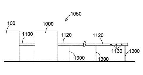
depicted in the side view of an exemplary overall system 1050 shown in FIG. 13
whereby a
series of stands 1300 are used to maintain some or all of distribution conduit
1120 above the
ground. A smaller distribution conduit 1120 results in less weight, and
therefore fewer or
smaller stands 1300 can be used to maintain the distribution conduit 1120
above the ground,
noting that attempting to elevate 6" or 8" diameter pipe above the ground,
such as in 1000',
2000', or larger or smaller sections, may/could be cost prohibitive.
A primary shortfall of using a single fan to generate and distribute vapor, as
compared to
Applicant's use of air flow generator 104 (within vapor generation system 100)
and air flow
generator 1100 (within vapor distribution system 1000), is that both the
output and the
- 13 -
CA 02996805 2018-02-27
WO 2017/035523 PCT/US2016/049217
generation of vapor are dependent upon variables that are often mutually
exclusive. For
example, the velocity of air striking a surface 152 of liquid chemical 150
within tank 102 is
likely different than the velocity of air necessary to move chemical vapor
through distribution
conduit(s) 1120 and therefore at odds with one another. By using a vapor
generation system 100
and a vapor distribution system 1000 of the present disclosure, each system
100, 1000 can be
specifically regulated and configured as desired, taking Bernoulli's
principles and the law of
conservation of energy, for example, into account.
Prior art systems drastically overestimate the cubic feet per minute (CFM)
necessary to
move the vapor through distribution pipes, and generally underestimate the
necessary static
pressure required to move vapor through said distribution pipes. One system in
particular bases
its fan sizing determination on horsepower, which generally does not make
sense, as horsepower
should only be considered after the correct size and shape of air flow
generator 104, such as a
fan, has been identified. An appropriate fan (air flow generator 104, 1100)
size and shape are a
direct function of the CFM and static pressure required for a given length of
pipe, such as one or
.. more distribution conduits 1120. The horsepower required to turn the
identified fan is then
determined by the manufacturer of the air flow generator 104, 1100. If the fan
(air flow
generator 1100, for example) and motor 1102 (if separate from air flow
generator 1100, noting
that air flow generators 104, 1100 of the present disclosure may comprise a
fan or a fan and a
motor, such as a motor 1102) were based solely on horsepower, such as 10hp and
1600 CFM, an
excessive amount of air flow would be generated, preventing proper laminar
flow through the
pipe (such as distribution conduit 1120), and instead generating extreme
turbulence which
results in highly decreased and volatile static pressure, as well as
significant backpressure into
housing 1104 and potentially back into tank 102 of vapor generation system
100. Prior art
systems generally use excessive horsepower, such that the turbulence and back
pressure cause
significant inefficiencies, whereas a properly sized airflow generator 1100
and motor 1102,
given a particular length and dimension of distribution conduit 1120, would
result in a highly
effective and efficient overall system 1050, as generally described herein.
Ultimate delivery of vapor via apertures 1130, using an efficient and
effective vapor
distribution system 1000, is one goal of the present disclosure. Considering a
stadium analogy,
say a stadium can hold 40,000 people, but it has only one door. No matter how
hard the crowd
would push, there is only one number of people that can fit through the door
at any given time.
An inefficient system, such as prior art systems using excessive horsepower
motors, excessively
large fans, etc., cause so much air flow that cannot make it out of the given
number of openings,
so that turbulence and backflow is the norm, rather than proper laminar flow.
Applicant's
present disclosure of systems 100, 1000, 1050 effectively address these
problems.
- 14 -
CA 02996805 2018-02-27
WO 2017/035523 PCT/US2016/049217
The appropriate approach is to initially determine the overall length of
distribution
conduit 1120 desired for a particular purpose, the number of apertures 1130
desired or needed,
and the overall size (diameter) of said distribution conduit 1120. A
model/working prototype
can then be constructed based on said dimensions, which, using the laws of
physics, can forecast
the overall parameters of air flow generator 1100 and/or motor 1102 needed to
achieve the
desired vapor distribution.
An additional embodiment of an overall system 1050 of the present disclosure
is shown
in FIG. 16. As shown therein, a vapor generation system 100 of the present
disclosure is
operably coupled to a vapor distribution system 1000 of the present
disclosure, with various
componentry/features as previously described. In at least this embodiment, a
controlled and
measurable volatilization/vaporization of liquid chemical 150 can be had,
which, in at least this
embodiment, requires that the airflow into tank 102, as generated by air flow
generator 104, has
a discharge capability (via aperture 160) equal or greater to the intake
capacity, for example, 5
cubic feet per minute (CFM) of air flow into tank 102 must allow for 5 CFM or
greater air flow
(of volatilized/vaporized chemical) out of aperture 160. FIG. 16 shows an
exemplary
embodiment for discharging the volatilized/vaporized chemical, whereby the
inlet conduit 1100
was relatively narrow (having a relatively small diameter, for example), and
therefore could not
successfully balance the incoming CFM with the vented/discharged CFM. In
attempt to correct
for this, and by increasing the size of aperture 160 of tank 102, such as to a
diameter of 3 inches
in at least one embodiment, the flow of air into tank 102 from air flow
generator 104 was
balanced with the outgoing flow of volatilized/vaporized chemical out of
aperture 160, allowing
for the rate of volatilization to be controllable and measurable by, for
example, adjusting air
flow velocity controller 108 to adjust the flow of air from air flow generator
104 into tank 102,
such as shown in FIG. 17. FIG. 17 shows an exemplary overall system 1050 of
the present
disclosure, whereby aperture 160 of tank 102 is larger than aperture 160 shown
in FIG. 16,
allowing for a larger inlet conduit 1110 to be used. Inlet conduit 1110, as
shown in FIG. 17 for
example, has a proximal end 1700 and a distal end 1702 defining a distal
opening 1704. Distal
end 1702, and therefore distal opening 1704, can then be positioned adjacent
to, but not actually
coupled to, an inlet 1710 of air flow generator 1100, so that
volatilized/vaporized chemical can
exit tank 102 via aperture 160, travel through inlet conduit 1110, and escape
from distal opening
1704, whereby some or all of the volatilized/vaporized chemical that escapes
from distal
opening 1704 would enter into inlet 1710 by way of suction/vacuum, as air flow
generator 1100,
in operation, would effectively suck in air, and/or volatilized/vaporized
chemical that may be
present in the vicinity of inlet 1710, so that it can ultimately escape air
flow generator 1100 via
aperture(s) 1130 of distribution conduit(s) 1120.
- 15 -
CA 02996805 2018-02-27
WO 2017/035523 PCT/US2016/049217
Upon identifying how to control the rate of vaporization, the discovery was
made that the
air flow velocity controller 108 (also referred to as an attenuating device,
which may be, for
example, a ball valve) must be, in at least some overall system 1050
embodiments, sufficiently
flexible to allow for subtle adjustments to air flow. As such, an air flow
velocity controller 108
other than a ball valve was tested, namely an air flow velocity controller 108
being/configured
as a gate valve, to allow for greater precision regarding adjustment of
airflow, such as shown in
FIG. 18. Additional precision was capable by way of connecting a gauge 1900 to
vapor
generation system 100, such as shown in FIG. 19, whereby gauge 1900 is
configured to
measure, for example, inches of water column, which is a method for measuring
static pressure.
Feedback from gauge 1900 allows a user of vapor generation system 100 to more
precisely
adjust air flow velocity controller 108 to obtain desired air flow through
vapor generation
system 100. By metering air flow prior to and after air flow velocity
controller 108, a reading of
X inches of water column, for example, can be correlated within Y units of
vapor production
from vapor generation system 100. Accordingly, and in at least one embodiment,
gauge 1900 is
connected to portions of vapor generation system 100 proximal to and distal to
air flow velocity
controller 108. In at least other embodiments, gauge 1900 is connected to
portions of vapor
generation system 100 proximal or distal to air flow reducer 106.
FIGS. 20A-20D show various views of an exemplary flotation element 132 of the
present disclosure. Via performance of various tests of various vapor
generation system 100
embodiments, it was observed that air flow directed vertically onto the
surface 152 of liquid
chemical 150, irrespective of velocity, could result in less controllable
and/or less efficient
vaporization/volatilization of chemical 150. In view of the same, additional
flotation element
132 embodiments, also referred to herein as diffusers, were designed and
configured so that they
redirect vertical flowing air into a laminar horizontal flow of air across a
broader surface area of
liquid chemical 150, which in at least some embodiments, resulted in more
controllable and
efficient vaporization/volatilization of chemical 150. As shown in one or more
of FIGS. 20A,
exemplary flotation elements 132 comprise an inlet portion 2000 defining an
inlet aperture 2002
therein, a first outlet portion 2004 defining a first outlet aperture 2006
therein, and a second
outlet portion 2008 defining a second outlet aperture 2010 therein. Air flow
from air flow
generator 104 would enter inlet aperture 2002 in a relative vertical
direction, and be diverted to a
horizontal/laminar flow direction within flotation element 132 and exit
horizontally through first
outlet aperture 2006 and second outlet aperture 2010. An internal lumen 2012,
such as shown in
FIG. 20C, would be defined within portions of inlet portion 2000, first outlet
portion 2004, and
second outlet portion 2008, in various embodiments.
- 16 -
CA 02996805 2018-02-27
WO 2017/035523 PCT/US2016/049217
FIG. 21 shows components of an overall system 1050 of the present disclosure
comprising a vapor generation system 100 and a vapor distribution system 1000,
according to an
exemplary embodiment of the present disclosure. Subsequent testing of the
combination of a
uniquely designed air diffuser (an exemplary air flow reducer 106 of the
present disclosure) and
a gate valve (an exemplary air flow velocity controller 108 of the present
disclosure) revealed a
flaw in a prototype design. Multiple tests revealed that, despite a balanced
flow of air into and
out of the evaporation tank (tank 102) at the beginning of the cycle, namely a
full tank 102 of
liquid chemical 150, as the level of liquid chemical 150 in tank 102 lessens
due to evaporation
(volatilization or vaporization of liquid chemical 150), static pressure of
system 100 necessarily
decreased. A lower static pressure implies an increase in air velocity
traveling through the
diffuser (air flow reducer 106) and therefore an increased level of production
of
volatilized/vaporized liquid chemical 150 as compared to the initial level of
production at the
full-tank amount. Therefore, it was discovered that either a constant
adjustment to air flow
within system 100 be made, namely to make static pressure constant by
consistent gradual
restriction of the gate valve (air flow velocity controller 108) or a method
of keeping the level of
liquid chemical 150 constant within tank 102 be engineered.
The choice was made to introduce a secondary feeder tank (an auxiliary feeder
tank
2100) from which the product (liquid chemical 150) to be evaporated
(volatilized/vaporized) is
pumped out of auxiliary feeder tank 2100 and into the evaporation tank (tank
102) at a rate equal
to or nearly equal to the rate of evaporation within tank 102. The desired
rate of evaporation
then becomes a function of static pressure as measured by inches of water
column (using a static
pressure gauge, which is an exemplary gauge 1900 of the present disclosure).
To achieve the
same, a pump 2102, such as shown in FIG. 21, can be used to pump liquid
chemical 150 from
auxiliary feeder tank 2100 to tank 102. A feeder tube 2104 coupled to pump
2102 can be used
to withdraw/pump liquid chemical 150 from auxiliary feeder tank 2100 and
into/through a pump
distribution tube 2106 into tank 150. Phrased differently, pump 2102 can have
a feeder tube
2104, and pump 2102 is configured to pump at least some of the liquid chemical
150 from
auxiliary feeder tank 2100 through feeder tube 2104, through pump distribution
tube 2106
coupled to pump 2102 or feeder tube 2104, and into tank 102.
In various system 100, 1000 embodiments, heaters 2110 can be used to increase
the
temperature of liquid chemical 150 within tank 102 and/or auxiliary tank 2100.
Increasing the
temperature of liquid chemical 150 within tank 102 and/or auxiliary tank 2100
can ultimately
improve overall efficiency of systems 100, 1000 by facilitating
volatilization/vaporization of
liquid chemical 150 within tank 102 with less overall effort/energy. Heaters
2110 can be
configured as immersion heaters 2110, as shown in FIG. 21, whereby portions of
heaters 2110
- 17 -
CA 02996805 2018-02-27
WO 2017/035523 PCT/US2016/049217
are immersed within liquid chemical 150. Heaters 2110 can be positioned
relative to tank 102
and/or auxiliary feeder tank 2100, as shown in FIG. 21. Overall levels of
liquid chemical 150
within tank 102 and/or auxiliary feeder tank 2100 can be monitored using one
or more level
sensors 2120, as shown in FIG. 21. Level sensors 2120, in various embodiments,
can be
electronic point-to-point level sensors 2120, configured to obtain data
relating to a level of first
chemical 150 within tank 102 and/or auxiliary feeder tank 2100. Said data can
be used to
control operation of pump 2102, for example, as if a level of liquid chemical
150 falls below a
desired level, pump 2102 can operate to pump liquid chemical 150 from
auxiliary feeder tank
2100 into tank 102 as described above.
A further refinement was realized by replacing the gate-valve (an exemplary
air flow
velocity controller 108) with an iris damper (another exemplary air flow
velocity controller
108). A gate-valve (exemplary air flow velocity controller 108) properly
reduces or increases
airflow depending on the user-defined setting. However, the change in airflow
as the setting is
adjusted is non-linear; for example, if one quarter-open is equal to 20 CFM,
half open is equal to
greater than 40 CFM. Therefore, an iris damper (exemplary air flow velocity
controller 108) can
be used in various system 100 embodiments, such as shown in FIG 21, to replace
the gate valve
(another exemplary air flow velocity controller 108) for a considerably more
linear rate of
change when increasing or decreasing air flow (lower or higher static
pressure) to achieve a
desired level of evaporation (volatilization/vaporization of liquid chemical
150). The iris
__ damper (exemplary air flow velocity controller 108) can therefore initially
be calibrated to meet
a desired evaporation rate, such as, for example, one inch of static pressure
(as measured by the
static pressure gauge 1900) being equal to 2.5 gallons of evaporated liquid
chemical 150 (in an
exemplary embodiment) and the level of liquid chemical 150 in the evaporation
tank 102 is held
constant vis-a-vis the constant transfer of liquid chemical 150 from the
auxiliary feeder tank
__ 2100.
Various information/data from systems 100, 1000, 1050, such as levels of
liquid
chemical 150 within tank 102 and/or auxiliary feeder tank 2100 (such as
detected using level
sensor(s) 2120), temperatures of liquid chemical 150 within tank 102 and/or
auxiliary feeder
tank 2100 (such as obtained/facilitated using heater(s) 2110), level(s) of
static pressure within
system 100 (such as determined using gauge 1900), etc., can all be obtained
and transmitted to
one or more clients 1412A, 1412B, 1412C, such as through a network 1414, as
shown in FIG.
14. This allows for remote monitoring of systems 100, 1000, and 1050, allowing
appropriate
responsive action to be taken, such as adding liquid chemical 150 to auxiliary
feeder tank 2100,
adjusting operation of heater(s) 2110, adjusting air flow velocity controller
108 to adjust static
pressure, and the like. FIG. 22 shows an exemplary system 1050 of the present
disclosure,
- 18 -
CA 02996805 2018-02-27
WO 2017/035523 PCT/US2016/049217
whereby various components of systems 100, 1000 are contained within an outer
housing 2200.
System 100 components and some system 1000 components can be contained within
outer
housing 2200, while portions of outlet conduit 1120 extend from outer housing
2200 so to allow
volatilized/vaporized liquid chemical 150 to be distributed as desired. Air
flow into system
occurs via housing vent 2202, and an optional filter 2204 can be used at
housing vent 2202 to
filter air. An indicator panel 2210 can be present upon outer housing 2200 to
indicate various
power and/or other levels of systems 100, 1000, 1050 as referenced herein.
Various vapor distribution systems 1000 of the present disclosure can be
positioned
relative to a source of noxious or otherwise offensive odors, taking into
account atmospheric air
movement. For example, portions of an exemplary vapor distribution system 1000
of the
present disclosure can be located upwind or downwind, as may be desired,
relative to the source
of said odors. Should portions of system 1000 be positioned upwind from said
odor source,
chemical vapor can be distributed prior to the location and travel over said
location to mix
and/or otherwise react with said odors to address the odor problem. Should
portions of system
1000 be positioned downwind from said odor source, chemical vapor can be
distributed as
desired when the odors arrive at system 1000 from the odor-causing location to
mix and/or
otherwise react with said odors to address the odor problem. Any number of
relative positions
of systems 100, 1000, 1050 of the present disclosure relative to a source of
odor are
contemplated within the present disclosure.
The present disclosure also includes disclosure of software used to
receive/accept
parameters/inputs and generate outputs with respect to said inputs, relating
to the generation
and/or distribution of chemical vapor. Said software 1416 (as a portion of an
exemplary
simulation system 1400) is described in further detail in connection with the
following.
Various techniques and mechanisms of the present disclosure will sometimes
describe a
connection between two components. Words such as attached, affixed, coupled,
connected, and
similar terms with their inflectional morphemes are used interchangeably
unless the difference is
expressly noted or made otherwise clear from the context. These words and
expressions do not
necessarily signify direct connections, but include connections through
mediate components and
devices. Indeed, it should be noted that a connection between two components
does not
necessarily mean a direct, unimpeded connection, as a variety of other
components may reside
between the two components of note. For example, a workstation may be in
communication
with a server, but it will be appreciated that a variety of bridges and
controllers may reside
between the workstation and the server. Consequently, a connection does not
necessarily mean
a direct, unimpeded connection unless otherwise noted.
Furthermore, wherever feasible and convenient, like reference numerals are
used in the
- 19 -
CA 02996805 2018-02-27
WO 2017/035523 PCT/US2016/049217
figures and the description to refer to the same or like parts or steps. The
drawings are in a
simplified form and not to precise scale.
The detailed descriptions which follow are presented in part in terms of
algorithms and
symbolic representations of operations on data bits within a computer memory
representing
alphanumeric characters or other information. A computer generally includes a
processor for
executing instructions and memory for storing instructions and data. When a
general purpose
computer has a series of machine encoded instructions stored in its memory,
the computer
operating on such encoded instructions may become a specific type of machine,
namely a
computer particularly configured to perform the operations embodied by the
series of
instructions. Some of the instructions may be adapted to produce signals that
control operation
of other machines and thus may operate through those control signals to
transform materials far
removed from the computer itself. These descriptions and representations are
the means used by
those skilled in the art of data processing arts to most effectively convey
the substance of their
work to others skilled in the art.
An algorithm is here, and generally, conceived to be a self-consistent
sequence of steps
leading to a desired result. These steps are those requiring physical
manipulations of physical
quantities. Usually, though not necessarily, these quantities take the form of
electrical or
magnetic pulses or signals capable of being stored, transferred, transformed,
combined,
compared, and otherwise manipulated. It proves convenient at times,
principally for reasons of
common usage, to refer to these signals as bits, values, symbols, characters,
display data, terms,
numbers, or the like as a reference to the physical items or manifestations in
which such signals
are embodied or expressed. It should be kept in mind, however, that all of
these and similar
terms are to be associated with the appropriate physical quantities and are
merely used here as
convenient labels applied to these quantities.
Some algorithms may use data structures for both inputting information and
producing
the desired result. Data structures greatly facilitate data management by data
processing
systems, and are not accessible except through software systems. Data
structures are not the
information content of a memory, rather they represent specific electronic
structural elements
which impart or manifest a physical organization on the information stored in
memory. More
than mere abstraction, the data structures are specific electrical or magnetic
structural elements
in memory which simultaneously represent complex data accurately, often data
modeling
physical characteristics of related items, and provide increased efficiency in
computer operation.
Further, the manipulations performed are often referred to in terms, such as
comparing or
adding, commonly associated with mental operations performed by a human
operator. No such
capability of a human operator is necessary, or desirable in most cases, in
any of the operations
- 20 -
CA 02996805 2018-02-27
WO 2017/035523 PCT/US2016/049217
described herein which form part of the embodiments of the present
application; the operations
are machine operations. Indeed, a human operator could not perform many of the
machine
operations described herein due, at least in part, to the vast distribution
capabilities of the present
disclosure.
Useful machines for performing the operations of one or more embodiments
hereof
include general purpose digital computers or other similar devices. In all
cases the distinction
between the method operations in operating a computer and the method of
computation itself
should be recognized. One or more embodiments of the present application
relate to methods
and apparatus for operating a computer in processing electrical or other
(e.g., mechanical,
chemical) physical signals to generate other desired physical manifestations
or signals. The
computer and systems described herein may operate on software modules, which
are collections
of signals stored on a media that represents a series of machine instructions
that enable the
computer processor to perform the machine instructions that implement the
algorithmic steps.
Such machine instructions may be the actual computer code the processor
interprets to
implement the instructions, or alternatively may be a higher level coding of
the instructions that
is interpreted to obtain the actual computer code. The software module may
also include a
hardware component, wherein some aspects of the algorithm are performed by the
circuitry
itself rather as a result of an instruction.
Some embodiments of the present disclosure also relate to an apparatus or
specific
hardware for performing the disclosed operations. This apparatus and/or
hardware may be
specifically constructed for the required purposes or it may comprise a
general purpose
computer or related hardware as selectively activated, employed, or
reconfigured by a computer
program stored in the computer. The algorithms presented herein are not
inherently related to
any particular computer or other apparatus unless explicitly indicated as
requiring particular
hardware. In some cases, the computer programs may communicate or relate to
other programs
or equipment through signals configured to particular protocols which may or
may not require
specific hardware or programming to interact (e.g., in at least one
embodiment, the computer
programs use a set of predefined APIs (defined below)). In particular, various
general purpose
machines may be used with programs written in accordance with the teachings
herein, or it may
prove more convenient to construct at least one more specialized apparatus to
perform the
required method steps. The required structure for a variety of these machines
will appear from
the description below.
Embodiments of the present invention may deal with "object-oriented" software,
and
particularly with an "object-oriented" operating system. The "object-oriented"
software is
organized into "objects," each comprising a block of computer instructions
describing various
- 21 -
CA 02996805 2018-02-27
WO 2017/035523 PCT/US2016/049217
procedures ("methods") to be performed in response to "messages" sent to the
object or "events"
which occur with the object. Such operations include, for example, the
manipulation of
variables, the activation of an object by an external event, and the
transmission of one or more
messages to other objects.
Messages are sent and received between objects having certain functions and
knowledge
to carry out processes. Messages may be generated in response to user
instructions, for
example, by a user activating an icon with a "mouse" pointer or fingertip,
thus generating an
event. Also, messages may be generated by an object in response to the receipt
of a message.
When one of the objects receives a message, the object carries out an
operation (a message
procedure) corresponding to the message and, if necessary, returns a result of
the operation.
Each object has a region where internal states (instance variables) of the
object itself are stored
and where the other objects are not allowed to access. One feature of the
object-oriented system
is inheritance. For example, an object for drawing a "circle" on a display may
inherit functions
and knowledge from another object for drawing a "shape" on a display.
A programmer "programs" in an object-oriented programming language by writing
individual blocks of code each of which creates an object by defining its
methods. A collection
of such objects adapted to communicate with one another by means of messages
comprises an
object-oriented program. Object-oriented computer programming facilitates the
modeling of
interactive systems in that each component of the system can be modeled with
an object, the
behavior of each component being simulated by the methods of its corresponding
object, and the
interactions between components being simulated by messages transmitted
between objects.
An operator may stimulate a collection of interrelated objects comprising an
object-oriented program by sending a message to one of the objects. The
receipt of the message
may cause the object to respond by carrying out predetermined functions which
may include
sending additional messages to one or more other objects. The other objects
may in turn carry
out additional functions in response to the messages they receive, including
sending still more
messages. In this manner, sequences of message and response may continue
indefinitely or may
come to an end when all messages have been responded to and no new messages
are being sent.
When modeling systems utilizing an object-oriented language, a programmer need
only think in
terms of how each component of a modeled system responds to a stimulus and not
in terms of
the sequence of operations to be performed in response to some stimulus. Such
sequence of
operations naturally flows out of the interactions between the objects in
response to the stimulus
and need not be preordained by the programmer.
Although object-oriented programming makes simulation of systems of
interrelated
components more intuitive, the operation of an object-oriented program is
often difficult to
- 22 -
CA 02996805 2018-02-27
WO 2017/035523 PCT/US2016/049217
understand because the sequence of operations carried out by an object-
oriented program is
usually not immediately apparent from a software listing as in the case for
sequentially
organized programs. Nor is it easy to determine how an object-oriented program
works through
observation of the readily apparent manifestations of its operation. Most of
the operations
carried out by a computer in response to a program are "invisible" to an
observer since only a
relatively few steps in a program typically produce an observable computer
output.
In the following description, several terms which are used frequently have
specialized
meanings in the present context. The term "API" relates to a set of computer
instructions and
associated data which can be activated directly or indirectly by the user. The
terms "windowing
environment," "running in windows," and "API-oriented operating system" are
used to denote a
computer user interface in which information is manipulated and displayed on a
video display
such as within bounded regions on a raster scanned video display. The terms
"network," "local
area network," "LAN," "wide area network," or "WAN" mean two or more computers
which are
connected in such a manner that messages may be transmitted between the
computers. In such
computer networks, typically one or more computers operate as a "server,"
which run one or
more applications capable of accepting requests from clients and giving
responses accordingly.
Servers can run on any computer including dedicated computers, which
individually are also
often referred to as "the server" and typically comprise ¨ or have access to ¨
large storage
devices (such as, for example, hard disk drives) and communication hardware to
operate
peripheral devices such as printers, webcams, or modems. Servers can also be
configured for
cloud computing, which is Internet-based computing where groups of remote
servers are
networked to allow for centralized data storage. Such cloud computing systems
enable users to
obtain online access to computer services and/or other resources despite such
users' potentially
diverse geographic locations.
Other computers, termed "workstations" or "clients," provide a user interface
so that
users of computer networks can access the network resources, such as shared
data files, common
peripheral devices, and inter-workstation communication. Users activate
computer programs or
network resources to create "processes" which include both the general
operation of the
computer program along with specific operating characteristics determined by
input variables
and its environment. Similar to a process is an agent (sometimes called an
intelligent agent),
which is a process that gathers information or performs some other service
without user
intervention and on some regular schedule. Typically, an agent, using
parameters typically
provided by the user, searches locations either on the host machine or at some
other point on a
network, gathers the information relevant to the purpose of the agent, and
presents it to the user
on a periodic basis. A "module" refers to a portion of a computer system
and/or software
- 23 -
CA 02996805 2018-02-27
WO 2017/035523 PCT/US2016/049217
program that carries out one or more specific functions and may be used alone
or combined with
other modules of the same system or program.
The term "desktop" means a specific user interface which presents a menu or
display of
APIs with associated settings for the user associated with the desktop. When
the desktop
accesses a network resource, which typically requires an application program
to execute on the
remote server, the desktop calls an Application Program Interface, or "API" to
allow the user to
provide commands to the network resource and observe any output. The term
"Browser" refers
to a program which is not necessarily apparent to the user, but which is
responsible for
transmitting messages between the desktop and the network server and for
displaying and
interacting with the network user. Browsers are designed to utilize a
communications protocol
for transmission of text and graphic information over a worldwide network of
computers,
namely the "World Wide Web" or simply the "Web." Examples of Browsers
compatible with
one or more embodiments described in the present application include, but are
not limited to, the
Chrome browser program developed by Google Inc. of Mountain View, California
(Chrome is a
trademark of Google Inc.), the Safari browser program developed by Apple Inc.
of Cupertino,
California (Safari is a registered trademark of Apple Inc.), Internet Explorer
program developed
by Microsoft Corporation (Internet Explorer is a trademark of Microsoft
Corporation), the Opera
browser program created by Opera Software ASA, or the Firefox browser program
distributed
by the Mozilla Foundation (Firefox is a registered trademark of the Mozilla
Foundation).
Although the following description details operations in terms of a graphic
user interface of a
Browser, it will be understood that one or more embodiments disclosed in the
present disclosure
may be practiced with text based interfaces, voice or visually activated
interfaces, or any other
interfaces now or hereinafter developed that have many of the functions of a
graphic based
Browser.
Browsers display information which is formatted in a Standard Generalized
Markup
Language ("SGML") or a HyperText Markup Language ("HTML"), both being
scripting
languages which embed non-visual codes in a text document through the use of
special ASCII
text codes. Files in these formats may be easily transmitted across computer
networks,
including global information networks like the Internet, and allow the
Browsers to display text,
images, and play audio and video recordings. The Web utilizes these data file
formats to
conjunction with its communication protocol to transmit such information
between servers and
workstations. Browsers may also be programmed to display information provided
in an
eXtensible Markup Language ("XML") file, with XML files being capable of use
with several
Document Type Definitions ("DTD") and thus more general in nature than SGML or
HTML.
The XML file may be analogized to an API, as the data and the stylesheet
formatting are
- 24 -
CA 02996805 2018-02-27
WO 2017/035523 PCT/US2016/049217
separately contained (formatting may be thought of as methods of displaying
information, thus
an XML file has data and an associated method). Similarly, JavaScript Object
Notation (JSON)
may be used to convert between data file formats.
The terms "personal digital assistant" or "FDA," as defined above, means any
handheld,
mobile device that combines computing, telephone, fax, e-mail and/or
networking features. The
terms "wireless wide area network" or "WWAN" mean a wireless network that
serves as the
medium for the transmission of data between a handheld device and a computer.
The term
"synchronization" means the exchanging of information between a first device
(e.g., a handheld
device) and a second device (e.g., a desktop computer), either via wires or
wirelessly.
Synchronization ensures that the data on both devices are identical (at least
at the time of
synchronization).
In wireless wide area networks, communication primarily occurs through the
transmission of radio signals over analog, digital cellular or personal
communications service
("PCS") networks. Signals may also be transmitted through microwaves and
other
electromagnetic waves. At the present time, most wireless data communication
takes place
across cellular systems using second generation technology such as code-
division multiple
access ("CDMA"), time division multiple access ("TDMA"), the Global System for
Mobile
Communications ("GSM"), Third Generation (wideband or "3G"), Fourth Generation
(broadband or "4G"), personal digital cellular ("PDC"), or through packet-data
technology over
analog systems such as cellular digital packet data (CDPD") used on the
Advance Mobile Phone
Service ("AMPS").
The terms "wireless application protocol" or "WAP" mean a universal
specification to
facilitate the delivery and presentation of web-based data on handheld and
mobile devices with
small user interfaces. "Mobile Software" refers to the software operating
system which allows
for application programs to be implemented on a mobile device such as a mobile
telephone,
PDA, tablet, wearable or smartphone. Examples of Mobile Software are Java and
Java ME
(Java and JavaME are trademarks of Sun Microsystems, Inc. of Santa Clara,
California), BREW
(BREW is a registered trademark of Qualcomm Incorporated of San Diego,
California),
Windows Mobile (Windows is a registered trademark of Microsoft Corporation of
Redmond,
Washington), Palm OS (Palm is a registered trademark of Palm, Inc. of
Sunnyvale, California),
Symbian OS (Symbian is a registered trademark of Symbian Software Limited
Corporation of
London, United Kingdom), ANDROID OS (ANDROID is a registered trademark of
Google,
Inc. of Mountain View, California), and iPhone OS (iPhone is a registered
trademark of Apple,
Inc. of Cupertino, California), and Windows Phone 7, etc. "Mobile Apps" refers
to software
programs written for execution with Mobile Software.
- 25 -
CA 02996805 2018-02-27
WO 2017/035523 PCT/US2016/049217
"PACS" refers to Picture Archiving and Communication System (PACS) involving
medical imaging technology for storage of, and convenient access to, images
from multiple
source machine types. Electronic images and reports are transmitted digitally
via PACS; this
eliminates the need to manually file, retrieve, or transport film jackets. The
universal format for
PACS image storage and transfer is DICOM (Digital Imaging and Communications
in
Medicine). Non-image data, such as scanned documents, may be incorporated
using consumer
industry standard formats like PDF (Portable Document Format) and the like,
once encapsulated
in DICOM. A PACS typically utilizes a secured network for the transmission of
images,
workstations and mobile devices for interpreting and reviewing images, and
archives for the
storage and retrieval of images and reports. When used in a more generic
sense, PACS may
refer to any image storage and retrieval system.
Now referring to an exemplary system architecture of the present disclosure,
FIG. 14 is
a high-level block diagram of a computing environment through which aspects of
a presently
disclosed simulation system and methods may be implemented. FIG. 14
illustrates a simulation
system 1400 of the present disclosure comprises one server 1410 and three
clients 1412
(represented as 1412A, 1412B, and 1412C in the figure) connected by network
1414. One or
more users (not shown), such as users or administrators, can access the system
via the one or
more clients 1412. Specifically, in at least one embodiment, the system 1400
of the present
disclosure is configured such that one or more users can access the particular
functionality of
and/or data stored within the server 1410 via a user interface (not shown) and
the network 1414.
The computing environment may be configured similarly to a multi-user site in
that numerous
parties may register and/or access the server 1410 via multiple ¨ and commonly
remote ¨ clients
1412. The server 1410 is operatively coupled with the clients 1412 over a
network 1414 or
networking infrastructure. For example and without limitation, the network
1414 may be
operatively coupled with clients 1412 via the Internet, intranet or other
connection.
It will be appreciated that only three clients 1412A, 1412B, and 1412C are
shown in
FIG. 14 in order to simplify and clarify the description and the same is not
intended to be
limiting. Indeed, embodiments of the computing environment may have thousands
or millions
of clients 1412 connected to network 1414, for example the Internet. Likewise,
while only one
server 1410 is depicted in FIG. 14, the computing environment may comprise a
plurality of
servers 1410.
The clients 1412 may each comprise one or more network accessible devices that
are
capable of executing one or more applications and/or accessing a web-based
system through a
Browser. A client 1412 may be any type of workstation such as, for example,
any type of
computer, computing device, or system of a type known in the art such as a
personal computer,
- 26 -
CA 02996805 2018-02-27
WO 2017/035523 PCT/US2016/049217
mainframe computer, workstation, notebook, tablet or laptop computer or
device, PDA, mobile
telephone or smartphone, wearable, or any other computing or communications
device having
network interfaces (wireless or otherwise). Additionally, users (not shown)
may operate
software 1416 (shown as software 1416A, 1416B, and 1416C in the figure) on one
or more of
clients 1412 to both send and receive messages over the network 1414 via
server 1410 and any
of its associated communications equipment and software (not shown). Further,
clients 1412
may each comprise hardware and componentry as would occur to one of skill in
the art such as,
for example, one or more microprocessors, memory, input/output devices, device
controllers,
and the like. Clients 1412 may also comprise one or more input devices that
are operable by a
user of the client 1412 such as, for example, a keyboard, keypad, pointing
device, mouse,
touchpad, touch screen, microphone, camera, webcam, and/or any other data
entry means (or
combination thereof) known in the art or hereinafter developed. Furthermore,
client 1412 may
also comprise visual and/or audio display means for displaying or emitting
output. For example,
a client 1412 may comprise a CRT display, an LCD display, a printer, one or
more speakers,
and/or any other types of display or output devices known in the art or
hereinafter developed.
The exact configuration of each client 1412 in any particular implementation
of a simulation
system 1400 hereof may vary between clients 1412 and may be left to the
discretion of the
practitioner.
As shown in FIG. 14, each client 1412 is connected to, and/or in communication
with,
the server 1410 via a network 1414. The network 1414 providing access to
and/or serving as
part of an exemplary simulation system 1400 of the present disclosure
comprises any means for
interconnecting the server 1410 and a client 1412. In at least one exemplary
embodiment, the
network 1414 comprises the Internet, a global computer network. Alternatively,
the network
1414 may be selected from a variety of different networks and/or cables
including, but not
limited to, a commercial telephone network, one or more local area networks,
one or more wide
area networks, one or more wireless communications networks, coaxial cable(s),
fiber optic
cable(s), and/or twisted-pair cable(s). Additionally, the network 1414 may
comprise equivalents
of any of the aforementioned, or combinations of two or more types of networks
and/or cables.
Furthermore, in at least one embodiment where the server 1410 and a client
1412
comprise a single computing device operable to perform the functions delegated
to both server
1410 and a client 1412 according to the present disclosure, the network 1414
may comprise the
hardware and software means interconnecting the server 1410 and client 1412
within the single
computing device. Accordingly, the network 1414 may comprise packet-switched
facilities
(such as the Internet), circuit-switched facilities (such as the public-
switched telephone
network), radio-based facilities (such as a wireless network), or any other
facilities capable of
- 27 -
CA 02996805 2018-02-27
WO 2017/035523 PCT/US2016/049217
interconnecting a client 1412 with the server 1410. Additionally, the clients
1412 and/or
wired/wireless connections may include the appropriate safeguards to ensure
that the
transmission of data between the server 1410 and each client 1412 is secure.
It will be appreciated that where the computing environment comprises a
plurality of
clients 1412, such clients 1412 need not all comprise the same type of client
1412 or be in
communication with the network 1414 and/or server 1410 via the same type of
communication
link. As such, the computing environment 1400 may comprise some clients 1412
configured to
connect to/communicate with the server 1410 via the Internet, for example,
while other clients
1412 are connected to the server 1410 via a wired connection (e.g., a cable).
The simulation system 1400 of the present disclosure may be implemented
through any
appropriate application architecture pattern now known or hereinafter
developed. In at least one
exemplary embodiment, the simulation system 1400 is delivered through an n-
tier architecture in
which presentation, application/business logic, and data management functions
are logically
and/or physically separated. This application architecture pattern provides
benefits in the way of
increasing availability of the system 1400 to its users (i.e. reduced
downtime), the minimization
of the impact of any component failure, and through facilitating disaster
recovery. Additionally,
if desired, third party applications may be interfaced with the system 1400
and provided to
system users without sacrificing data security as such third party
applications need not be in
direct communication with the data structures of the system 1400.
As described above, the clients 1412 of the computing environment each
comprise a user
interface (not shown) to facilitate a user's input into and access to the
functionality of and/or
data stored within the server 1410. The user interface can be any interface
known in the art that
is appropriate to achieve such a purpose and is fully customizable. The user
interface may be
local to a client 1412, provided over the network 1414, or stored within the
server 1410. In at
.. least one embodiment, the user interface comprises a web-based portal that
provides
functionality for accessing and displaying data stored within the server 1410.
In at least one
exemplary embodiment, the user interface comprises a mobile application and/or
widget
designed to run on smartphones, tablet computers, wearables, and other mobile
devices.
The simulation system 1400 need not be limited geographically. Users from all
over the
world can participate, if desired, as there is no inherent restriction as to
the number of users who
can access and use the simulation system 1400 at a single time. In at least
one exemplary
embodiment, the simulation system 1400 is delivered as an open platform
environment, where
anyone with access to the Internet may register as a user of the system 1400.
Accordingly, by
entering a publicly available website, a user can register and gain access to
the functionality
provided by the simulation system 1400.
- 28 -
CA 02996805 2018-02-27
WO 2017/035523 PCT/US2016/049217
Now referring to FIG. 15, a block diagram of a computer system 1510 suitable
for
implementing the simulation system 1400 via server 110 or client 1412 is
shown. Computer
system 1510 includes bus 1512 that interconnects major subsystems of computer
system 1510,
such as central processor 1514, system memory 1517 (typically RAM, but which
may also
include ROM, flash RAM, or the like), input/output controller 1518, external
audio device, such
as speaker system 1520 via audio output interface 1522, external device, such
as display screen
1524 via display adapter 1526, serial ports 1528 and 1530, keyboard 1532
(interfaced with
keyboard controller 1533), storage interface 1534, disk drive 1537 operative
to receive floppy
disk 1538, host bus adapter (HBA) interface card 1535A operative to connect
with Fibre
Channel network 1590, HBA interface card 1535B operative to connect to SCSI
bus 1539, and
optical disk drive 1540 operative to receive optical disk 1542. Also included
are mouse 1546 (or
other point-and-click device, coupled to bus 1512 via serial port 1528), modem
1547 (coupled to
bus 1512 via serial port 1530), and network interface 1548 (coupled directly
to bus 1512).
Bus 1512 allows data communication between central processor 1514 and system
memory 1517, which may include read-only memory (ROM) or flash memory (neither
shown),
and random access memory (RAM) (not shown), as previously noted. RAM is
generally the
main memory into which operating system and application programs are loaded.
ROM or flash
memory may contain, among other software code, Basic Input-Output system
(BIOS) which
controls basic hardware operation such as interaction with peripheral
components. Applications
resident with computer system 1510 are generally stored on and accessed via
computer readable
media, such as hard disk drives (e.g., fixed disk 1544), optical drives (e.g.,
optical drive 1540),
floppy disk unit 1537, or other storage medium. Additionally, applications may
be in the form
of electronic signals modulated in accordance with the application and data
communication
technology when accessed via network modem 1547 or interface 1548 or other
telecommunications equipment (not shown).
Storage interface 1534, as with other storage interfaces of computer system
1510, may
connect to standard computer readable media for storage and/or retrieval of
information, such as
fixed disk drive 1544. Fixed disk drive 1544 may be part of computer system
1510 or may be
separate and accessed through other interface systems. Modem 1547 may provide
direct
connection to remote servers via telephone link or the Internet via an
internet service provider
(ISP) (not shown). Network interface 1548 may provide direct connection to
remote servers via
direct network link to the Internet via a POP (point of presence). Network
interface 1548 may
provide such connection using wireless techniques, including digital cellular
telephone
connection, Cellular Digital Packet Data (CDPD) connection, digital satellite
data connection or
the like.
- 29 -
CA 02996805 2018-02-27
WO 2017/035523 PCT/US2016/049217
Many other devices or subsystems (not shown) may be connected in a similar
manner
(e.g., document scanners, digital cameras, and so on). Conversely, all of the
devices shown in
FIG. 15 need not be present to practice the present disclosure. Furthermore,
devices and
subsystems may be interconnected in different ways from that shown in FIG. 15.
Operation of a
computer system such as that shown in FIG. 15 is readily known in the art and
is not discussed
in detail in this application. Software source and/or API specifications to
implement the present
disclosure may be stored in computer-readable storage media such as one or
more of system
memory 1517, fixed disk 1544, optical disk 1542, or floppy disk 1538. The
operating system
provided on computer system 1510 may be a variety or version of either MS-DOS
(MS-DOS
is a registered trademark of Microsoft Corporation of Redmond, Washington),
WINDOWS
(WINDOWS is a registered trademark of Microsoft Corporation of Redmond,
Washington),
OS/20 (0S/2 is a registered trademark of International Business Machines
Corporation of
Armonk, New York), UNIX (UNIX is a registered trademark of X/Open Company
Limited of
Reading, United Kingdom), Linux (Linux is a registered trademark of Linus
Torvalds of
Portland, Oregon), or other known or developed operating system. In some
embodiments,
computer system 1510 may take the form of a tablet computer, typically in the
form of a large
display screen operated by touching the screen. In tablet computer alternative
embodiments, the
operating system may be iOS (i0S is a registered trademark of Cisco Systems,
Inc. of San Jose,
California, used under license by Apple Corporation of Cupertino, California),
Android
(Android is a trademark of Google Inc. of Mountain View, California),
Blackberry Tablet OS
(Blackberry is a registered trademark of Research In Motion of Waterloo,
Ontario, Canada),
webOS (webOS is a trademark of Hewlett-Packard Development Company, L.P. of
Texas),
and/or other suitable tablet operating systems.
Moreover, regarding the signals described herein, those skilled in the art
will recognize
that a signal may be directly transmitted from a first block to a second
block, or a signal may be
modified (e.g., amplified, attenuated, delayed, latched, buffered, inverted,
filtered, or otherwise
modified) between blocks. Although the signals of the certain embodiments
described herein
are characterized as transmitted from one block to the next, other embodiments
of the present
disclosure may include modified signals in place of such directly transmitted
signals as long as
the informational and/or functional aspect of the signal is transmitted
between blocks. To some
extent, a signal input at a second block may be conceptualized as a second
signal derived from a
first signal output from a first block due to physical limitations of the
circuitry involved (e.g.,
there will inevitably be some attenuation and delay). Therefore, as used
herein, a second signal
derived from a first signal includes the first signal or any modifications to
the first signal,
- 30 -
CA 02996805 2018-02-27
WO 2017/035523 PCT/US2016/049217
whether due to circuit limitations or due to passage through other circuit
elements which do not
change the informational and/or final functional aspect of the first signal.
An exemplary simulation system 1400 can utilize software 1416, as referenced
herein, to
provide flow simulation modeling as may be desired for a particular vapor
generation system
100 and/or vapor distribution system 1000 of the present disclosure. For
example, software
1416 can utilize one or more inputs such as ambient air temperature, dew
point, location
elevation, latitude and longitude, diameter of distribution conduit 1120,
length of distribution
conduit 112, number of apertures 1130, size of apertures 1130, flow rate of
air flow generator
1100, operating pressure, etc., and generate one or more outputs, such as air
density (pounds per
cubic foot), air viscosity, Reynolds number, initial air/vapor velocity,
kinetic energy, friction
factors, flow per aperture 1130 (in CFM), mass flow per aperture 1130 (in
pounds per hour),
aperture 1130 velocity, etc. For a given length and diameter of distribution
conduit 1120 with a
specified number and size of apertures 1130, said outputs can be generated
using software 1416.
In view of the same, the present disclosure includes disclosure of s
simulation system 1400,
using software 1416, to generate various outputs using various inputs as
referenced herein, so
that configurations of vapor generation systems 100 and/or vapor distribution
systems 1000 of
the present disclosure can be determined and ultimately constructed and used
as desired.
While various embodiments of vapor generation and distribution devices and
systems
and methods for using the same to generate and distribute vapor have been
described in
considerable detail herein, the embodiments are merely offered as non-limiting
examples of the
disclosure described herein. It will therefore be understood that various
changes and
modifications may be made, and equivalents may be substituted for elements
thereof, without
departing from the scope of the present disclosure. The present disclosure is
not intended to be
exhaustive or limiting with respect to the content thereof.
Further, in describing representative embodiments, the present disclosure may
have
presented a method and/or a process as a particular sequence of steps.
However, to the extent
that the method or process does not rely on the particular order of steps set
forth therein, the
method or process should not be limited to the particular sequence of steps
described, as other
sequences of steps may be possible. Therefore, the particular order of the
steps disclosed herein
should not be construed as limitations of the present disclosure. In addition,
disclosure directed
to a method and/or process should not be limited to the performance of their
steps in the order
written. Such sequences may be varied and still remain within the scope of the
present
disclosure.
- 31 -