Note: Descriptions are shown in the official language in which they were submitted.
GAS TURBINE ENGINE FAN BLADE CONTAINMENT SYSTEMS
FIELD OF THE DISCLOSURE
This disclosure relates generally to aircraft gas turbine engines and, more
particularly, to fan blade containment systems.
BACKGROUND
For safety and survivability reasons, airplanes with multiple gas turbine
engines
are typically required to have gas turbine engine fan blade containment
(GTEFBC)
systems, which are typically integrated with each engine. In the event of a
fan blade
failure, these systems prevent fan blade fragments from being ejected through
the fan
casing of the faulty engine. By doing so, these systems protect the
surrounding
engines, critical subsystems, weapons, and airframe structure from damage and
allow
the pilot to continue flying and safely land the airplane. Airplanes with a
single jet
engine, on the other hand, are typically not required to have GTEFBC systems
because they add weight and cost to the aircraft and because they may reduce
the
likelihood of survival of the pilot and the aircraft. In some instances, an
ejected fan
blade that is contained within an engine housing may cause more damage to the
surrounding fan blades and engine machinery than a fan blade that can escape
from
the engine. In the event of a fan blade failure in a single engine airplane,
the pilot will
either eject immediately or attempt to continue flying and land, depending on
the
severity of the damage to the airplane.
SUMMARY
An example fan blade containment system includes a shield to be coupled to an
aircraft structure and to at least partially surround a circumference of an
aircraft engine.
The shield is to form a laminated clevis at an end of the shield. A retention
rod is to be
positioned in the laminated clevis of the shield.
Another example fan blade containment system includes a shield having a
unitary body including a first end and a second end opposite the first end.
The shield
includes an impact absorbing material that is to absorb kinetic energy from
fan blade
- 1 -
CA 2996810 2018-02-27
fragments during a fan blade failure event. A first retention rod is coupled
to the first end
of the shield. The first retention rod is to couple the shield to a first
structural member of
an aircraft structure. A second retention rod is coupled to the second end of
the shield.
The second retention rod is to couple the shield to a second structural member
of the
.. aircraft structure.
A fan blade containment system includes a means for capturing and absorbing
impact energy of fan blade fragments during a fan blade failure event of an
aircraft
engine. The means for capturing and absorbing is to be spaced from an outer
surface
of the aircraft engine when the means for capturing and absorbing is coupled
to the
aircraft structure. The means for capturing and absorbing having a terminating
end that
includes means for coupling the means for capturing and absorbing to the
aircraft
structure. The means for coupling includes: means for fastening the
terminating end of
the means for capturing and absorbing to the aircraft structure; and means for
receiving
the means for fastening.
In one embodiment, there is provided a fan blade containment system comprising
a shield to be coupled to an aircraft structure and to at least partially
surround a
circumference of an aircraft engine, the shield to be spaced from an outer
surface of the
aircraft engine when the shield is coupled to the aircraft structure and the
shield forming
a laminated clevis at an end of the shield. The system further comprises a
retention rod
to be positioned in the laminated clevis of the shield the retention rod is to
engage a lug
hook of the aircraft structure and anchor the shield to the aircraft
structure.
The end of the shield may include a small access cut-out to enable a lug hook
projecting from an aircraft structure to couple to the retention rod.
The shield may include a first layer, a second layer, and a third layer, the
second
layer may be positioned between the first layer and the third layer.
The first layer and the third layer may be coupled to the second layer via
adhesive.
The first layer may include steel, the second layer may include a dry Kevlar
fabric,
and the third layer may include aluminum.
The second layer may include a first portion folded over a second portion to
form
a loop at the end.
- 2 -
Date Recue/Date Received 2021-07-23
The end of the shield may include a composite laminate.
The shield may be a continuous or unitary body.
The shield may include multiple discrete shield segments.
The retention rod may be to engage a lug hook of the aircraft structure and
anchor
the shield to the aircraft structure.
In another embodiment, there is provided a fan blade containment system
comprising a shield having a unitary body including a first end and a second
end opposite
the first end, the shield including impact absorbing material that is to
absorb kinetic
energy from fan blade fragments during a fan blade failure event. The system
further
includes a first retention rod coupled to the first end of the shield, the
first retention rod
structured to engage a first structural member of an aircraft structure to
anchor the shield
to the aircraft structure. The system further includes a second retention rod
coupled to
the second end of the shield, the second retention rod to engage a second
structural
member of the aircraft structure to anchor the shield to the aircraft
structure.
The shield may include a first small access cut-out adjacent to the first end
of the
shield to enable the first retention rod to couple to the first structural
member.
The shield may include a second small access cut-out adjacent to the second
end
of the shield to enable the second retention rod to couple to the second
structural
member.
The first end of the shield and the second end of the shield may include a
composite laminate.
The first end of the shield may include a first laminated clevis to receive
the first
retention rod and the second end of the shield may include a second laminated
clevis to
receive the second retention rod.
The shield may include a first layer, a second layer and a third layer, the
second
layer may be positioned between the first layer and the third layer, the
second layer may
form the first laminated clevis at a first end of the second layer and the
second laminated
clevis at a second end of the second layer opposite the first end.
The first structural member may have an integral first lug hook and the second
structural member has an integral second lug hook.
- 3 -
Date Recue/Date Received 2021-07-23
In another embodiment, there is provided a fan blade containment system
comprising a shield to be coupled to an aircraft structure and to at least
partially surround
a circumference of an aircraft engine, the shield to be spaced from an outer
surface of
the aircraft engine when the shield is coupled to the aircraft structure and
the shield
forming a laminated clevis at an end of the shield. The shield includes a
first layer, a
second layer, and a third layer. The second layer is positioned between the
first layer
and the third layer and the first layer and the third layer are coupled to the
second layer
via adhesive. The system further includes a retention rod to be positioned in
the
laminated clevis of the shield.
In another embodiment, there is provided a fan blade containment system
comprising a shield to be coupled to an aircraft structure and to at least
partially surround
a circumference of an aircraft engine, the shield to be spaced from an outer
surface of
the aircraft engine when the shield is coupled to the aircraft structure. The
shield forms
a laminated clevis at an end of the shield and includes a first layer, a
second layer and a
third layer. The second layer is positioned between the first layer and the
third layer.
The first layer includes steel, the second layer includes a dry Kevlar fabric,
and the third
layer includes aluminum. The system further includes a retention rod to be
positioned in
the laminated clevis of the shield.
BRIEF DESCRIPTION OF THE DRAWINGS
FIG. 1 is an example aircraft engine without an integral fan blade containment
system.
FIG. 2 is a side view of the example aircraft engine of FIG. 1 implemented
with an
example fan blade containment system in accordance with the teachings of this
.. disclosure.
FIG. 3 is a front view of the example aircraft engine and the example fan
blade
containment system of FIG. 2.
FIG. 4A is a top view of the example aircraft engine and fan blade containment
system taken along line 4A-4A of FIG. 3.
- 4 -
Date Recue/Date Received 2021-07-23
FIG. 4B is a side view of the example aircraft engine and fan blade
containment
system taken along line 4B-4B of FIG. 3.
FIG. 5 is a cross-sectional view of the example fan blade containment system
taken along line 5-5 of FIG. 3.
FIG. 6 is a cross-sectional view of the example fan blade containment system
taken along line 6-6 of FIG. 3.
FIG. 7 is a close-up side view of the fan blade containment shield of the
example
fan blade containment system taken along line 7-7 of FIG. 3.
- 4a -
Date Recue/Date Received 2021-07-23
FIG. 8 is a cross-sectional view of the example fan blade containment system
taken along line 8-8 of FIG. 7.
FIG. 9 illustrates the fan blade containment system of FIGS. 1-3, 4A, 4B, 5-8
disclosed herein decoupled from an example aircraft structure.
FIG. 10 illustrates the fan blade containment system of FIGS. 1-3, 4A, 4B, 5-8
disclosed herein coupled to an example aircraft structure.
Certain examples are shown in the above-identified figures and described in
detail below. In describing these examples, like or identical reference
numbers are
used to identify the same or similar elements. The figures are not necessarily
to scale
and certain features and certain views of the figures may be shown exaggerated
in
scale or in schematic for clarity and/or conciseness. Additionally, several
examples
have been described throughout this specification. Any features from any
example
may be included with, a replacement for, or otherwise combined with other
features
from other examples. As used in this patent, stating that any part is in any
way
positioned on (e.g., located on, disposed on, formed on, coupled to, etc.)
another part,
means that the referenced part is either in contact with the other part, or
that the
referenced part is spaced from the other part (e.g., with one or more
intermediate
part(s) located there between). Stating that any part is in direct contact
with another
part means that there is no intermediate part between the two parts.
DETAILED DESCRIPTION
Engine selection is one of the most important steps in new aircraft design and
development. An aircraft manufacturer can either select an existing production
engine
that meets all the performance requirements of the new aircraft design or, if
no such
production engine exists, the aircraft manufacturer can work with an engine
company to
develop a new engine design that will meet all the requirements. As used
herein, a
production engine may be an engine that has been designed, tested, and
certified and
is in current production by an engine manufacturer. Designing, developing,
testing, and
certifying a new engine is a very expensive and time consuming process. Thus,
aircraft
manufacturers prefer to select a production engine (e.g., an "off-the-self"
production
engine) over investing in a new engine design and development effort.
- 5 -
CA 2996810 2018-02-27
When developing a new multi-engine airplane, an aircraft manufacturer usually
selects a production engine designed with an integrated fan blade containment
system
(e.g., an integrated, continuous hoop GTEFBC system).
Integrated fan blade
containment systems are typically formed as a continuous hoop or cylinder
(e.g.,
having a circular cross-section) that wraps around the entire circumference of
an
aircraft engine. Such known fan blade containment systems provide a
lightweight
and/or optimal system given that these fan blade containment systems are
designed
concurrently with the aircraft engine.
However, selecting an aircraft engine with an integrated, continuous hoop
GTEFBC system limits the number of production engines that are available for
selection and these engines may not be optimal for a new vehicle (e.g. due to
limited
performance characteristics). As an alternative strategy, an aircraft
manufacturer may
select an engine that was originally designed without an integrated,
continuous hoop
GTEFBC system (e.g. an engine originally designed for a single engine
airplane) and
may request that the engine company redesign the engine to include an
integrated,
continuous hoop GTEFBC system. However, redesigning an engine to include an
integrated blade containment system (e.g., a continuous hoop system) typically
requires retesting and recertification of the redesigned engine, which can be
exceedingly expensive and may prolong the vehicle development schedule. Thus,
redesigning an aircraft engine to include an integrated blade containment
system
diminishes the cost and the schedule advantages of selecting an existing
production
engine.
Therefore, in some instances, the best existing production engine selected for
a
new multi-engine airplane does not have an integrated GTEFBC system (i.e. the
engine was originally designed for a single engine plane). Rather than
redesign the
engine with an integrated GTEFBC system, and then retest, and requalify the
engine,
the example methods and apparatus disclosed herein provide an economical and
effective engine fan blade containment system that may be integrated with the
airframe
and completely external to the engine.
The example fan blade containment systems disclosed herein are not integrated
with the engine. In some examples, example fan blade containment systems
disclosed
- 6 -
CA 2996810 2018-02-27
herein do not form a continuous circumferential hoop around the engine.
Example fan
blade containment systems disclosed herein include a shield, placed between
the
engine and the surrounding airframe, that is to be coupled to the aircraft
structure and
that is to at least partially surround a circumference of the aircraft engine.
In this
example system, an ejected fan blade can escape the engine housing, thus
minimizing
damage to the engine machinery, but is prevented from escaping the engine bay
of the
airframe, thus minimizing the risk of damage to adjacent airframe structure,
subsystems, weapons, fuel tanks, etc. To save weight and cost, the shield may
provide fan blade containment protection only to critical aircraft systems
(e.g., partially
surround a circumference of an aircraft engine to minimize the weight of
example blade
containment systems disclosed herein).
Example fan blade containment systems disclosed herein enable an aircraft
manufacturer to select an optimal production engine for a new multi-engine
aircraft
regardless of whether the production engine includes an integrated fan blade
containment system. The example fan blade containment systems disclosed herein
can be implemented with existing production aircraft engines without requiring
retesting
and/or recertification of an aircraft engine. In this manner, an aircraft
manufacturer
avoids costs and/or schedule impact of redesigning, retesting and/or
recertifying an
engine that was originally designed without an integrated fan blade
containment
system.
Example fan blade containment systems disclosed herein partially surround a
circumference of an aircraft engine. In some such examples, the example fan
blade
containment systems disclosed herein include a shield or shield body having a
first end
anchored to a first aircraft structural member (e.g., an aircraft keel) and a
second end
opposite the first end anchored to a second aircraft structural member. To
enable
attachment of the shield body to the aircraft structure, the example fan blade
containment systems disclosed herein employ connectors positioned at the
respective
first and second ends of the shield body. For example, an example connector
may be
a rod, a pin and/or other fastener that may couple with or be anchored to an
aircraft
structure. For example, the mating connector on the aircraft structure may
include a
lug hook that is integrally formed with a keel of the aircraft structure.
Thus, example
- 7 -
CA 2996810 2018-02-27
connectors of the shield disclosed herein provide mechanical joints for the
ends of the
shield body and/or the notched, cut-out, or segmented areas of the shield
body. In
some examples, a coupling or joint between an example shield and an aircraft
structure
disclosed herein transfers load from a shield body (e.g., a high impact energy
absorbing material of the body) to an aircraft structural member (e.g. an
aircraft keel,
deck or frame).
Example shields of example fan blade containment systems disclosed herein
provide adequate clearance to the outer surface of the aircraft engine to
provide space
for engine bay ventilation, pathways for subsystems routings, and room to
allow for
routine engine bay maintenance (e.g. without engine or shield removal, etc.).
To
ensure normal engine operation, the shield should not insulate or restrict
airflow around
the engine. As used herein, the term "normal operation" means that the
aircraft engine
operates at temperatures below a threshold maximum engine operating
temperature.
Example shields of example fan blade containment systems disclosed herein
may be notched, cut-out, and/or a segmented, as needed, to accommodate
structural
obstacles within the engine bay (e.g. engine mounts). These notches and/or cut-
outs,
in some instances, may produce discontinuities in the fan blade containment
protection
provided by the shield. In some examples, the aircraft structure or airframe
adjacent to
these notched, cut-out, and/or segmented areas (e.g., the areas not covered by
the
shield body) may be reinforced with a high strength material with the ability
to absorb
large amounts of kinetic energy (e.g., steel) to accommodate or compensate for
the
discontinuity in fan blade containment protection provided by the shield body.
In some
such examples, the aircraft structure and/or airframe adjacent to the notched,
cut-out,
and/or segmented areas of the shield body may include an increased dimensional
characteristic (e.g., a greater thickness). In some such examples, the
aircraft structure
and/or airframe adjacent to the notched, cut-out, and/or segmented areas of
the shield
body may include a reinforcement plate (e.g., a metal plate composed of
stainless
steel) to increase a structural characteristic of the aircraft structure
and/or airframe. In
some examples, the reinforced areas function similarly to the fan blade
containment
shield body by preventing fan blade fragments from penetrating through the
reinforced
areas of the aircraft structure and/or airframe that are exposed adjacent to
the notched,
- 8 -
CA 2996810 2018-02-27
cut-out, or segmented portions of a shield body. Thus, a notched, cut-out,
and/or
segmented shield and an aircraft structure that has been selectively
reinforced adjacent
to the notched, cut-out, and/or segmented areas of the shield can effectively
provide
continuous fan blade containment protection.
In some examples, the notched, cut-out, and/or segmented areas of the shield
may include a shield termination joint to anchor the notched, cut-out, and/or
segmented
portions of the shield body to the aircraft structure (e.g., via a pinned lug
and clevis
joint). Thus, example shield terminations disclosed herein provide mechanical
joints for
terminating ends of the shield body and/or the notched, cut-out, or segmented
areas of
the shield body. The example shield terminations disclosed herein may include
an
integral laminated clevis, a retention pin, and a mating lug hook on the
aircraft side. In
some examples, example shield termination joints disclosed herein transfer
load from
the shield body (e.g., a high impact energy absorbing material of the body) to
an
aircraft structural member (e.g. an aircraft keel, deck or frame).
Example fan blade containment systems disclosed herein may include either a
single shield segment or multiple shield segments, depending on the
application. Each
shield segment may be a unitary body including a first end and a second end
opposite
the first end. The first end of the example fan blade containment system
shield
segment may couple to a first aircraft structural member (e.g., a first engine
bay keel)
and the second end may couple to a second aircraft structural member (e.g., a
second
engine bay keel). Each shield segment of the example fan blade containment
systems
disclosed herein may include a kinetic energy absorbing material (e.g., dry
Kevlar
fibers, dry Kevlar fabric, or any other lightweight, high toughness fiber)
that is to prevent
high speed fan blade fragments from escaping an engine bay during a fan blade
failure
event. A first connector (e.g., a shield termination connector) of the example
fan blade
containment systems disclosed herein may include a first laminated clevis and
a first
retention pin. The first connector couples the first end of the shield to a
first mating
coupler (e.g., a first lug hook) on the aircraft structure. A second connector
(e.g., a
second shield termination connector) of the example fan blade containment
systems
disclosed herein may include a second laminated clevis and a second retention
pin.
- 9 -
CA 2996810 2018-02-27
The second connector couples the second end of the shield to a second mating
coupler
(e.g., a second lug hook) of the aircraft structure.
FIG. 1 shows a trimetric view of an example aircraft engine 100. The aircraft
engine 100 of the illustrated example is an example production gas turbine
engine that
was originally designed without an integrated fan blade containment system.
The
aircraft engine 100 of the illustrated example includes a housing 102 that
houses an
intake fan 104 having fan blades 114 that draw air into the aircraft engine
100.
FIG. 2 is a side view of the aircraft engine 100 of FIG. 1 implemented with an
example fan blade containment system 200 constructed in accordance with the
teachings of this disclosure. The fan blade containment system 200 of the
illustrated
example is capable of capturing fragments of the fan blades 114 of the intake
fan 102
as a result of fan blade failure.
FIG. 3 is a front view of the aircraft engine 100 and the fan blade
containment
system 200 of FIG. 2. The aircraft engine 100 and the fan blade containment
system
200 of the illustrated example are mounted to an aircraft structure 302 of an
aircraft
302a. For example, the aircraft engine 100 and the fan blade containment
system 200
of the illustrated example are positioned within an engine bay 304 of the
aircraft 302a.
The engine bay 304 of the illustrated example is formed by engine bay keels
300 and
an upper engine bay deck 300a. The aircraft engine 100 of the illustrated
example is
coupled to an engine mount hanger link fitting 306 via an engine hanger link
308. In
some examples, the engine mount hanger link fitting 306 may be manufactured to
be
integral with or mechanically attached (e.g., fastened) to the upper engine
bay deck
300a. In addition, the aircraft engine 100 of the illustrated example is
coupled with an
engine mount side link fitting 310 via a side link 312. In some examples, the
engine
mount side link fitting 310 may be manufactured to be integral with or
mechanically
attached (e.g., fastened) to the engine bay keel 300. The engine hanger link
308 and
the side link 312 of the illustrated example are attached to the housing 102
of the
aircraft engine 100. Some example aircraft and/or aircraft engine bays may
include
additional mounting structure(s) and/or mount(s) (e.g., thrust mounts, aft
side links,
etc.).
- 10 -
CA 2996810 2018-02-27
The fan blade containment system 200 of the illustrated example is positioned
externally relative to the housing 102 of the aircraft engine 100. For
example, the fan
blade containment system 200 is not directly attached to the housing 102 of
the aircraft
engine 100 and/or is not positioned inside the housing 102 of the aircraft
engine 100.
Thus, the fan blade containment system 200 of the illustrated example is not
integral
with the aircraft engine 100. Although the fan blade containment system 200 of
the
illustrated example is not integral with the aircraft engine 100, the fan
blade
containment system 200 of the illustrated example captures fan blade fragments
during
blade failure, absorbs impact energy from the fan blade fragments, and
transfers the
energy to the aircraft structure 302.
The fan blade containment system 200 of the illustrated example is coupled
(e.g., directly coupled or anchored) to the aircraft structure 302 of the
aircraft 302a.
When coupled to the aircraft structure 302, the fan blade containment system
200 of
the illustrated example is offset or positioned a distance 314 away from the
housing
.. 102 of the aircraft engine 100 to provide spacing 316 (e.g., a gap) between
(e.g., an
inner surface of) the fan blade containment system 200 and (e.g., an outer
surface of)
the aircraft engine 100. In this manner, the fan blade containment system 200
does not
affect the thermal profile and normal operation of the aircraft engine 100.
Thus, an
aircraft engine such as the aircraft engine 100 of FIG. 1 that is retrofit
with the fan blade
containment system 200 of the illustrated example does not require re-testing
and/or
re-certification because the fan blade containment system 200 does not affect
the
normal operation of the aircraft engine 100.
Additionally, because the fan blade containment system 200 of the illustrated
example is coupled externally relative to the aircraft engine 100, the spacing
316
between the fan blade containment system 200 of the illustrated example and
the
aircraft engine 100 enables access to the aircraft engine 100 (e.g., engine
system
routings) and/or the engine bay 304 without having to remove the fan blade
containment system 200 (e.g., during routine maintenance of the aircraft
engine 100).
For example, the fan blade containment system 200 of the illustrated example
may be
shaped or positioned to provide convenient access to components of the
aircraft engine
100 and/or the engine bay 304 of the aircraft 302a.
- 11 -
CA 2996810 2018-02-27
In some examples, the fan blade containment system 200 of the illustrated
example may be replaced with a different fan blade containment system composed
of
different material(s) (e.g., a lower weight and/or higher strength
material(s)). As
described in greater detail below, the fan blade containment system 200 of the
illustrated example may be formed with varying dimensions and/or volumes,
varying
material(s) composition, and/or shape to improve performance (e.g., energy
absorption) characteristic(s).
The fan blade containment system 200 of the illustrated example at least
partially surrounds a circumference of the aircraft engine 100 (e.g., the fan
blades 114
.. of the intake fan 104). In the illustrated example, the fan blade
containment system
200 of the illustrated example surrounds a portion of a circumference of the
aircraft
engine 100 while leaving another portion of the circumference of the aircraft
engine 100
uncovered (e.g., exposed). For example, as shown in FIG. 3, the fan blade
containment system 200 is positioned around partial areas of the aircraft
engine 100
(e.g., lateral sides and a top side of the aircraft engine 100) and other non-
critical areas
are uncovered (e.g., a bottom side of the aircraft engine 100). A bottom side
of the
aircraft engine 100, for example, may be a non-critical area because blade
fragments
that may pierce the engine bay 304 eject in a downward direction during flight
and
away from other components (e.g., critical components such as weapons, fuel,
etc.) of
the aircraft 302a. Additionally, providing the fan blade containment system
200 around
only a portion (e.g., the critical areas with high probability trajectories)
of the aircraft
engine 100 reduces weight of the fan blade containment system 200, thereby
improving aircraft performance (e.g., fuel efficiency). However, in some
examples, the
fan blade containment system 200 (e.g., the shield) may be positioned to
surround
(e.g., encase) the entire circumference of the aircraft engine 100. To enable
the fan
blade containment system 200 to surround an entire circumference of the
aircraft
engine 100, the fan blade containment system 200 may include a portion (e.g.,
a
segment) extending underneath the aircraft engine 100 and coupled to another
airframe structure (e.g. an engine bay lower cover panel) positioned
underneath the
aircraft engine 100. To facilitate engine bay access, the lower segment of the
shield
- 12 -
CA 2996810 2018-02-27
can be integrated with the lower engine bay cover and can be designed to be
removed/installed with the cover during engine bay maintenance activities.
To capture and/or absorb impact energy of fan blade fragments, the fan blade
containment system 200 of the illustrated example includes a shield 318. The
shield
318 of the illustrated example is positioned around at least a portion of the
aircraft
engine 100. The shield 318 of the illustrated example includes a first face or
impact
face 320 oriented or facing toward the housing 102 of the aircraft engine 100
and a
second face or outer face 322 oriented or facing away from the housing 102 of
the
aircraft engine 100.
To couple (e.g., anchor or fix) the shield 318 to the aircraft structure 302,
the
shield 318 of the illustrated example includes a shield termination connector
324 at
each end 326 of the shield 318. In the illustrated example, each end 326 of
the shield
318 is defined as a portion of the shield 318 that is to couple to the
aircraft structure
302. Specifically, the shield termination connector 324 and the aircraft
structure 302 of
the illustrated example form one or more joints 328 (e.g. high strength
joints) when the
shield 318 is coupled to the aircraft structure 302. The joints 328 provide a
load path to
transfer the fan blade impact energy from the shield 318 to the aircraft
structure 302.
During an impact event, the shield 318 of the illustrated example may flex or
stretch
when fan blade fragments impact the shield 318. The joints 328 of the
illustrated
example retain or capture the ends 326 of the shield 318 and prevent the ends
326
from decoupling from the aircraft structure 302 during an impact event (e.g.,
when the
shield 318 deflects relative to the ends 326).
To minimize these deflections and to enable the shield 318 to maintain its
shape
when the aircraft 302a performs flight maneuvers, the shield 318 of the
illustrated
example includes one or more stiffeners 330. The stiffeners 330 of the
illustrated
example are attached to the impact face 320 of the shield 318. In the
illustrated
example, respective ends of the stiffeners 330 terminate prior to reaching the
ends 326
of the shield 318. The stiffeners 330 of the illustrated example may be
machined,
formed (e.g., pre-formed) and/or otherwise have a profile (e.g., a contoured
profile)
substantially similar (e.g., identical) to the shape of the shield 318 portion
or segment to
which the stiffeners 330 are attached. For example, the stiffeners 330 of the
illustrated
- 13 -
CA 2996810 2018-02-27
example have a curved or arcuate shape or profile similar to the arcuate shape
or
profile of the shield 318. The stiffeners 330 may be formed of aluminum,
carbon//epoxy
composite and/or any other suitable material(s).
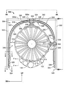
FIG. 4A is a top view of the fan blade containment system 200 of FIGS. 2 and
3.
FIG. 4B is a side view of the fan blade containment system 200 of FIGS. 2, 3
and 4A.
The aircraft engine 100 is omitted from FIGS. 4A and 4B for clarity. Referring
to FIGS.
4A and 4B, the shield 318 of the illustrated example includes a first end 402
and a
second end 404 opposite the first end 402. The first end 402 of the
illustrated example
is coupled to a first engine bay keel 406 (e.g., a frame or deck) of the
aircraft structure
302 and the second end 404 is coupled to a second engine bay keel 408 (e.g., a
frame
or deck) of the aircraft structure 302. To enable the shield 318 to fit around
structural
elements or structural obstacles of the aircraft structure 302, the shield 318
of the
illustrated example includes one or more cut-out or notched openings 410. For
example, the shield 318 of the illustrated example includes a first notched
opening
410a (FIG. 4A) adjacent to the engine mount hanger link fitting 306 and a
second
notched opening 410 (FIG. 4B) adjacent to the engine mount side link fitting
310 to
enable the shield 318 to fit around the engine hanger link 308 and the side
link 312.
The first end 402, the second end 404, and/or the openings 410 may form the
terminating ends 326 of the shield 318.
In some examples, the aircraft structure 302 may be reinforced (e.g.,
hardened)
to provide fan blade containment in areas of the aircraft structure 302 that
are exposed
by the one or more notched openings 410 of the shield 318 (i.e., not covered
by the
shield 318). The reinforced and/or hardened aircraft structure 302 exposed
adjacent
the one or more notched openings 410 compensates for the discontinuity in the
shield
318 of the fan blade containment system 200 and prevents a fan blade fragment
from
piercing through the aircraft structure 302 exposed by the one or more notched
openings 410. To reinforce the aircraft structure 302 (e.g., exposed by the
notched
openings 410), the aircraft structure 302 may be reinforced with (e.g.,
composed of)
high strength material(s) (e.g. titanium, stainless steel, Inconel, etc.)
and/or provided
with a thickness increase (e.g., an increased thickness compared to portions
of the
aircraft structure 302 that are covered by the shield 318). For example,
portions of the
- 14 -
CA 2996810 2018-02-27
aircraft structure 302 adjacent to the one or more notched openings 410 (e.g.,
exposed
portions of the aircraft structure 302) may include one or more plates (e.g.,
stacked
plates) composed of high strength material(s) that may be attached or coupled
to the
aircraft structure 302 adjacent to the one or more opening 410 to reinforce
the aircraft
structure 302. For example, (e.g., at least a portion of) the upper engine bay
deck 300a
and/or the engine mount hanger link fitting 306 may be reinforced with (e.g.,
composed
of) high strength material(s) (e.g. titanium, stainless steel, Inconel, etc.)
and/or provided
with a thickness (e.g., an increased thickness) to reinforce the aircraft
structure 302
adjacent to (e.g., exposed by) the first notched opening 410a. For example,
one or
more plates (e.g., stacked plates) composed of high strength material(s) may
be
attached or coupled to the upper engine bay deck 300a and/or the engine mount
hanger link fitting 306 exposed adjacent to the first notched opening 410a to
increase a
thickness of the aircraft structure 302 adjacent to (e.g., exposed by) the
first notched
opening 410a. Likewise, (e.g., at least a portion of) the engine bay keel 300
and/or the
engine mount side link fitting 310 positioned (e.g., exposed) adjacent to the
second
notched opening 410b may also be composed of high strength material(s) (e.g.
titanium, stainless steel, Inconel, etc.) and/or provided with an increased
thickness to
reinforce the aircraft structure 302 exposed by the second notched opening
410b. In
some examples, one or more plates may be coupled or attached to the engine bay
keel
300 and/or the engine mount side link fitting 310 exposed adjacent to the
second
notched opening 410b to increase the thickness of the aircraft structure 302
exposed
by the second notched opening 410b.
The first end 402 of the shield 318 of the illustrated example has a first
plurality
412 of the shield termination connectors 324 and the second end 404 opposite
the first
end 402 has a second plurality 414 of the shield termination connectors 324.
The first
plurality 412 of the shield termination connectors 324 couple (e.g., anchor)
the shield
318 to the first engine bay keel 406 and the second plurality 414 of the
shield
termination connectors 324 couple (e.g., anchor) the second end 404 of the
shield 318
to the second engine bay keel 408. The shield 318 includes a third plurality
416 of the
shield termination connectors 324 to couple (e.g., anchor) the shield 318 to
the engine
mount hanger link fitting 306 and a fourth plurality 418 of the shield
termination
- 15 -
CA 2996810 2018-02-27
connectors 324 to couple (e.g., anchor) the shield 318 to the engine mount
side link
fitting 310. In some examples, a front edge 420a and/or a rear edge 420b of
the shield
318 may also include the shield termination connectors 324 to couple (e.g.,
anchor) the
front edge 420a and/or the rear edge 420b to the aircraft structure 302.
Additionally,
the shield 318 of the illustrated example includes one or more body couplers
422 that
couple the shield 318 to the aircraft structure 302. The body couplers 422
help support
the weight of the shield 318 and transfer inertial loads of the shield 318 to
the aircraft
structure 302. However, in some examples, the body couplers 422 may not be
used.
The shield 318 of the illustrated example has a unitary body between the first
end 402 and the second end 404. However, in some examples, the shield 318 may
include a plurality of shields or shield segments. For example, the engine
mount
hanger link fitting 306 and/or the engine mount side link fitting 310 may
extend between
the front edge 420a and the rear edge 420b (e.g., an entire width of the
shield 318
between the front edge 420a and the rear edge 420b). In some such examples,
the
shield 318 of the illustrated example may include a first shield segment
having first and
second ends (e.g., terminating ends) coupled to the first engine bay keel 406
and the
engine mount hanger link fitting 306 extending between the front edge 420a and
the
rear edge 420b. In some such examples, the shield 318 may include a second
shield
segment having first and second ends (e.g., terminating ends) coupled to the
engine
mount hanger link fitting 306 and the engine mount side link fitting 310
extending
between the front edge 420a and the rear edge 420b. In some such examples, the
shield 318 may include a third shield segment having first and second ends
(e.g.,
terminating ends) coupled to the engine mount side link fitting 310 extending
between
the front edge 420a and the rear edge 420b and the second engine bay keel 408.
.. Each of the respective first and second ends of the shield segments may
include the
shield termination connectors 324 to couple the respective first and second
ends to the
aircraft structure 302. As described below in connection with FIG. 5, the
shield 318 of
the illustrated example may include a plurality of closed or fibrous loops 424
(e.g.,
loops 424a-e) and small access cut-outs 428 (e.g., "mouse-hole" shaped cut-
outs, slits,
openings, etc.).
- 16 -
CA 2996810 2018-02-27
FIG. 5 is a cross-sectional view of the fan blade containment system 200 taken
along line 5-5 of FIG. 3. In the illustrated example, the shield 318 is a
multi-layer
shield. The shield 318 of the illustrated example includes a first layer 502
(e.g., an
inner layer), a second layer 504 (e.g. middle layer), and a third layer 506
(e.g., an outer
layer). The first layer 502 of the illustrated example defines the impact face
320 of the
shield 318 and the third layer 506 of the illustrated example defines the
outer face 322
of the shield 318. To surround the aircraft engine 100, the first layer 502,
the second
layer 504 and/or the third layer 506 may be shaped with an arcuate profile
such as, for
example, a profile of the shield 318 (e.g., the impact face 320 and the outer
face 322)
shown in FIG. 3.
The first layer 502 of the shield 318 of the illustrated example provides a
first
resistance to the fan blade fragments during a fan blade failure. For example,
the first
layer 502 of the illustrated example blunts edges of the fan blade fragments
prior to fan
blade fragments impacting the second layer 504. The first layer 502 of the
illustrated
example is a sheet or plate composed of a high strength material such as, for
example,
steel (e.g., stainless steel, Inconel, etc.), titanium and/or any other
suitable material(s).
In the illustrated example, the second layer 504 is an impact absorbing layer
that
captures or absorbs impact energy (e.g., kinetic energy) from fan blade
fragments to
prevent or restrict penetration of the fan blade fragments to the third layer
506. The
second layer 504 may restrict penetration of the fan blade fragments by
significantly
reducing a velocity and/or force of the fan blade fragments prior to the fan
blade
fragments reaching the third layer 506. In some examples, the second layer 504
may
prevent penetration of the fan blade fragments from reaching the third layer
506. In
some examples, if a fan blade fragment penetrates the second layer 504 and
reaches
the third layer 506, the energy of the fan blade fragment is reduced
significantly such
that the fan blade fragment cannot exit the third layer 506 and/or cannot
damage
surrounding components of the aircraft 302a should the fan blade fragment exit
the
third layer 506.
The second layer 504 of the illustrated example may be composed of a light
weight, high impact energy absorbing material such as, for example, Kevlar
(e.g.,
Kevlar fabric, dry Kevlar fibers, etc.). For example, the second layer 504 of
the
- 17 -
CA 2996810 2018-02-27
illustrated example includes multiple plies of dry Kevlar fabric, cloth, or a
braided Kevlar
fiber weave. In some examples, the second layer 504 may be dry Kevlar fibers
that
may be woven or braided to form the second layer 504 of the shield 318. The
Kevlar
fabric/weave may include interconnected fibers that form a lattice pattern.
For
example, a first set of fibers may be positioned substantially perpendicular
(e.g., non-
parallel) relative to a second set of fibers. In some examples, to increase
the strength
of the second layer 504, a thickness of the second layer 504 may be increased.
For
example, a thicker Kevlar fiber weave or a plurality of Kevlar cloth plies may
be stacked
to define the second layer 504.
The third layer 506 of the illustrated example provides backing/support to the
second layer 504. The third layer 506 of the illustrated example is a plate or
sheet
composed of a lighter weight material compared to the first layer 502. For
example, the
third layer 506 of the illustrated example is composed of aluminum. In some
examples,
the third layer 506 may be composed of composite material(s) such as, for
example, a
Kevlar/epoxy laminate, a carbon/epoxy laminate, etc. Given that the first
layer 502
provides impact resistance and the second layer 504 absorbs a substantial
portion of
the impact energy, the third layer 506 may be composed of a lighter material
to reduce
weight of the fan blade containment system 200. However, in some examples, the
third layer 506 may be composed of high strength material (e.g., stainless
steel) similar
to the first layer 502 to provide an additional barrier to fan blade fragments
that may
pass through the second layer 504. Thus, in some examples, the third layer 506
may
be composed of the same material as the first layer 502. In some examples, the
third
layer 506 is composed of a material (e.g., aluminum, titanium, etc.) that is
different than
the material of the first layer 502 (e.g. steel). In some examples, to
increase the
strength of the third layer 506, a thickness of the third layer 506 may be
increased. For
example, a thicker aluminum sheet or a plurality of aluminum sheets may be
stacked to
define the third layer 506.
Referring also to FIG. 4A & 4B, the second layer 504 of the shield 318 may
include or form the plurality of fibrous loops 424. The fibrous loops 424 of
the
illustrated example are fabricated by wrapping dry Kevlar fabric or
braiding/weaving dry
Kevlar fibers into a continuous cylinder, hoop, or any other closed loop shape
that has
- 18 -
CA 2996810 2018-02-27
a thickness equal to half the desired thickness of the second layer 504. In
particular,
the fibrous loops 424 of the illustrated example form a continuous Kevlar
cylinder,
hoop, or closed loop shape that are then flattened or collapsed and contoured
into the
shape of the shield 318, such that opposite walls of the Kevlar cylinder,
hoop, or closed
loop shape come in contact and can be stitched together in the thickness
direction to
form the respective one of the fibrous loops 424a-e. Each fibrous loop 424 of
the
illustrated example is stitched such that a cylindrical opening or sleeve
(e.g., a
laminated clevis 606 of FIG. 6) at each end 326 is formed to receive or
accommodate
the insertion of a high strength (e.g. steel) retention rod (e.g., the
retention rod 608 of
FIG. 6), used for anchoring the energy absorbing second layer 504 to the
aircraft
structure 302. For optimal shield strength, the direction of the continuous
Kevlar fibers
is oriented in the circumferential direction of the shield (i.e. the retention
rods run
parallel to the fore-aft axis of the engine). To reinforce the ends 326 of the
fibrous
loops 424, the dry fiber can be impregnated with an epoxy resin (or any other
suitable
polymeric resin) to form a Kevlar/epoxy laminated clevis (e.g., the laminated
clevis 606
of FIG. 6). To access the retention rod, the small access cut-outs 428 (e.g.,
"mouse
hole" shaped cut-outs) can be machined into the laminated clevis ends of the
fibrous
loops 424. Each shield termination connector 324 includes the laminated clevis
(e.g.,
the laminated clevis 606 of FIG. 6) of a respective one of the fibrous loops
424 and a
retention rod (e.g., the retention rod 608 of FIG. 6) that is accessed through
the small
access cut-outs 428 (e.g., the mouse hole cut-out). The shield termination
connector
324, the laminated clevis, and the retention rod are discussed in greater
detail in
connection with FIG. 6.
Multiple fibrous loops (e.g. dry Kevlar fabric loops, braided dry Kevlar fiber
loops,
etc.) enable the shield 318 to be notched to fit around structural elements or
structural
obstacles of the aircraft structure 302 while maintaining structural integrity
in the
circumferential direction (i.e. hoop strength). For example, the shield 318 of
the
illustrated example includes a first fibrous loop 424a (FIG. 4A), a second
fibrous loop
424b, a third fibrous loop 424c, a fourth fibrous loop 424d, and a fifth
fibrous loop 424e.
For example, the first fibrous loop 424a is coupled to a first engine bay keel
406 (e.g., a
frame or deck) of the aircraft structure 302 and the engine mount hanger link
fitting 306,
- 19 -
CA 2996810 2018-02-27
the second fibrous loop 424b is coupled to the engine mount hanger link
fitting 306 and
the engine mount side link fitting 310, the third fibrous loop 424c (FIG. 4B)
is coupled to
the engine mount side link fitting 310 and a second engine bay keel 404b
(e.g., a frame
or deck), the fourth fibrous loop 424d is coupled to the engine mount hanger
link fitting
306 and the second engine bay keel 408, and the fifth fibrous loop 424e is
coupled to
the first engine bay keel 406 and the second engine bay keel 408. To form a
continuous second layer 504, each fibrous loop 424 is stitched to a
neighboring/adjacent fibrous loop 424. In some examples, the shield 318 of the
illustrated does not require any large cut-outs or notches and the second
layer 504 may
be formed as a unitary body.
Each fibrous loop 424a-e of the illustrated example includes a first end 326a
(e.g., a respective one of the ends 326) having a shield termination connector
324a and
a second end 326b (e.g., a respective one of the ends 326) having a second
shield
termination connector 324. Each of the fibrous loops 424 may have different
dimensional characteristic(s) (e.g., fore-aft lengths and circumferential
widths) to fit
around elements of the aircraft structure 302. For example, the first fibrous
loop 424a
of the illustrated example of FIG. 4A includes a forward-aft length that is
substantially
similar to the fore-aft length of the engine mount hanger link fitting 306.
The second
fibrous loop 424b and the third fibrous loop 424c of the illustrated example
of FIG. 4A
.. and 4B each have a forward-aft length that is substantially similar to the
fore-aft length
of the engine mount side link fitting 310. The fourth fibrous loop 424d of the
illustrated
example of FIG. 4A and 4B has a forward-aft length that is substantially
similar to the
difference between the fore-aft length of the engine mount hanger link fitting
306 and
the fore-aft length of the engine mount side link fitting 310. The fifth
fibrous loop 424e
.. of the illustrated example of FIG. 4A and 4B includes a forward-aft length
that is
substantially similar to the fore-aft length between the rear edge 420b and
the aft end
of the engine mount hanger link fitting 306. Additionally, the fibrous loops
424 may
have different circumferential widths to accommodate different structural
elements of
the aircraft structure 302. The fibrous loops 424a-d have circumferential
widths that
are smaller than the circumferential width of the fifth shield portion 424e.
- 20 -
CA 2996810 2018-02-27
As noted above, only a notched shield requires that the second layer be
divided
into fibrous loops. To form the notched shield 318 as a unitary body, the
first layer 502
of the shield 318 may be formed as a notched, unitary body and the third layer
506 of
the shield 318 may be formed as a separate notched, unitary body. To form the
second layer 504 as a unitary body, the fibrous loops 424a-e of the
illustrated example
are coupled or spliced together attached via stitches 523 and/or any other
method of
splicing dry Kevlar fabric or dry Kevlar fibers. For example, the fibrous
loops 424a-e
(e.g., formed from a dry Kevlar fabric or dry Kevlar fibers) may be spliced or
stitched
together to form a unitary second layer 504 of the notched shield 318. During
a fan
blade impact event, a majority of the membrane loads induced in the second
layer 504
of the shield 318 are transmitted in the circumferential direction, from the
impact site to
the nearest shield termination connector 324. The membrane loads in the fore-
aft
direction are much less, therefore, splicing the second layer 504 in the fore-
aft direction
should produce a structurally acceptable solution.
A forward edge 510 and/or an aft edge 512 of the shield 318 of the illustrated
example include close-out stiffeners 514 (e.g., Z-shaped stiffeners, etc.) to
maintain a
shape of the shield 318 and/or to cover or seal (e.g., protect) the second
(e.g. dry
Kevlar fiber) layer 504 from the engine bay 304 environment (e.g., elevated
temperatures, moisture, engine oil, JP-8 fuel, etc.). The Z-shaped stiffeners
514 may
be attached to the first layer 502 and/or the third layer 506 via mechanical
fasteners
(e.g., rivets), adhesive (e.g., epoxy, rubber sealant, etc.), spot welds,
and/or any other
fastening method(s). For example, a first flange 516 of the Z-shaped
stiffeners 514
may be attached to an inner surface 518 of the impact face 320 and/or the
first layer
502 and a second flange 520 of the Z-shaped stiffeners 514 may be attached to
the
outer face 322 of the third layer 506. For example, the Z-shaped stiffeners
514 may be
attached to the first layer 502 and/or the third layer 506 (e.g., to the inner
surface 518
of the impact face 320 and the outer face 322) via protruding head blind
rivets,
adhesive and/or any other fastening method(s). The Z-shaped stiffeners 514 of
the
illustrated example extend an entire length of the forward edge 510 and an
entire
length of the aft edge 512, respectively. However, in some examples, the Z-
shaped
- 21 -
CA 2996810 2018-02-27
stiffeners 514 may extend along only a portion of the length of the forward
edge 510
and/or the aft edge 512.
As noted above, the shield 318 of the illustrated example also includes
multiple
circumferential panel stiffeners 330 (e.g., T-shaped stiffeners). The T-shaped
stiffeners
330 of the illustrated example include a face 522 (e.g., a flange) to couple
the T-shaped
stiffeners 330 to the first layer 502. For example, the T-shaped stiffeners
330 of the
illustrated example may be attached to the impact face 320 of the first layer
502 via
mechanical fasteners (e.g., protruding head blind rivets, screws, etc.),
adhesive (e.g.,
epoxy, rubber sealant, etc.), spot welds, and/or any other fastening
method(s).
To couple the first layer 502 and the second layer 504 and/or the third layer
506
and the second layer 504, the fan blade containment system 200 of the
illustrated
example employs an adhesive 524 (e.g., an adhesive bondline). The adhesive 524
may be a rubber adhesive, a rubber sealant (e.g. polysulfide), and/or any
other suitable
bonding agent. For example, the shield 318 of the illustrated example includes
a first
adhesive layer 526 between the first layer 502 and the second layer 504, and a
second
adhesive layer 528 between the second layer 504 and the third layer 506.
Because the
second layer includes multiple dry Kevlar fabric and/or braided Kevlar fiber
plies, the
plies of the illustrated example are stitched together to enable the second
layer to
behave as one cohesive entity. The first adhesive layer 526 couples (e.g.,
bonds) the
first layer 502 and the second layer 504, and the second adhesive layer 528
couples
(e.g., bonds) the third layer 506 and the second layer 504. For example, the
adhesive
524 may be employed to enable the second layer 504, composed of dry Kevlar
fibers,
to bond or attach to the first layer 502, composed of stainless steel, and/or
the third
layer 506, composed of aluminum and/or stainless steel.
In some examples, to add rigidity to the shield and to ensure that the first
layer
502 engages (e.g. directly contacts or tightly presses up against) the second
layer 504
and that the second layer engages (e.g., directly contacts or tightly press up
against)
the third layer 506, the shield 318 of the illustrated example includes one or
more
intermediate fasteners 530 (e.g., blind rivets, bolts and nuts). The
intermediate
fasteners 530 may pass through at least portions of the first layer 502, the
second layer
504 and/or the third layer 506. In some examples, the shield 318 may not
include the
- 22 -
CA 2996810 2018-02-27
Z-shaped stiffeners 514, the T-shaped stiffeners 330, the first adhesive layer
526, the
second adhesive layer 528, the stitches 523 and/or the intermediate fasteners
530.
FIGS. 6 is a cross-sectional view of the fan blade containment system 200
taken
along line 6-6 of FIG. 3. In the illustrated example, to couple the shield 318
to the
aircraft structure 302, the aircraft structure 302 of the illustrated example
employs one
or more lug hooks 602. For example, the lug hooks 602 of the illustrated
example are
integrally formed with the aircraft structure 302. For example, FIG. 6
illustrates the lug
hooks 602 formed with the first engine bay keel 406. The lug hooks 602 of the
second
engine bay keel 408, the engine mount hanger link fitting 306 and/or the
engine mount
side link fitting 310 are similar to the lug hooks 602 of the first engine bay
keel 406
shown in FIG. 6. The lug hooks 602 protrude from a surface or face 604 of the
aircraft
structure 302 (e.g., the first engine keel 404a as shown in FIG. 6).
The lug hooks 602 of the illustrated example are configured to receive the
shield
termination connectors 324, which includes a laminated clevis 606 (e.g., a
sleeve) and
a retention rod 608 (e.g., positioned in or received by the laminated clevis
606) at the
ends 326 of the shield 318 to provide the joints 328 (e.g., a lug hook and
laminated
clevis pinned joint). The joints 328 of the illustrated example provide a load
path from
the shield 318 to the aircraft structure 302. The lug hooks 602 of the
illustrated
example are formed with the aircraft structure 302 and are coupled with the
retention
rod 608 of the shield termination connector 324. In operation, during a fan
blade
impact event, for example, membrane loads transfer loads from the second layer
504
of the shield 318 to the laminated clevises 606 and retention rods 608 of the
shield
termination connectors 324 and then to the mating lug hooks 602 of the
aircraft
structure 302. During a fan blade impact event, at least a portion of the
shield 318 of
the illustrated example may deflect or bend (e.g., expands) when the shield
318
absorbs impact energy from the fan blade fragments while the shield
termination
connectors 324 and the joints 328 (e.g., a lug hook and laminated clevis
pinned joint,
including the lug hook 602, the laminated clevis 606, and the retention rod
608)
maintain the shield 318 anchored to the aircraft structure 302. The shield 318
of the
illustrated example prevents or restricts the fan blade fragments from exiting
the engine
bay 304. The joints 328 provide a load path to enable the transfer of forces
absorbed
- 23 -
CA 2996810 2018-02-27
by the shield 318 to the aircraft structure 302. Thus, relatively high,
transient
membrane loads generated in the shield 318 by the fan blade fragments may be
effectively transferred to the joints 328 and reacted by the aircraft
structure 302.
Further, during an impact event, the joints 328 provide sufficient holding
force to
prevent the ends 326 of the shield 318 from decoupling from the aircraft
structure 302.
FIG. 7 is a close-up side view of a portion 700 of the shield 318 of FIGS. 2,
3, 4A
and 4B taken along line 7-7 of FIG. 3. The portion 700 of the illustrated
example is a
first terminating end 326a of the shield 318 having shield termination
connectors 324a
(e.g., integral with the shield 318). The portion 700 of the illustrated
example can be
implemented at the first end 402, the second end 404, the one or more notched
openings 410, and/or any other portion of the shield 318 defining a
terminating end
(e.g., the terminating ends 326) of the shield 318 having one or more of the
shield
termination connectors 324 that couple or attach to the aircraft structure 302
(e.g. the
lug hooks 602).
To form the shield termination connectors 324, the end 326 of the shield 318
extends from an end 702 of the first layer 502 (e.g., and/or the third layer
506). In other
words, at least a portion 704 of the second layer 504 extends or protrudes
from the end
702 of the first layer 502 (e.g., and/or the third layer 506) to couple or
attach to the lug
hooks 602 via the laminated clevis 606 and the retention rod 608.
To enable the second layer 504 of the illustrated example to couple to the lug
hooks 602 and transfer loads from the shield 318 to the lug hooks 602, at
least the
portion 704 of the ends 326 of the second layer 504 of the illustrated example
includes
a reinforced end 706. The reinforced end 706 of the illustrated example is
integrally
formed with and/or attached to the second layer 504. In other words, the
reinforced
end 706 of the illustrated example is unitary (e.g., integral) with the second
layer 504.
The reinforced end 706 of the illustrated example increases strength
characteristic(s) of
the ends 326 to enable the shield 318 to couple to the lug hooks 602 via the
retention
rod 608. For example, the reinforced end 706 of the illustrated example
provides the
laminated clevis 606 (e.g., integrally formed with the second layer 504)
formed at the
ends 326 of the shield 318 that receives the retention rod 608. Each of the
joints 328
of the illustrated example is a pinned hook lug and laminated clevis joint
(e.g., a pinned
- 24 -
CA 2996810 2018-02-27
lug and clevis fastening system). The reinforced end 706 of the illustrated
example is a
composite laminate. Because the retention rods 608 transfer high loads from
the
laminated clevises 606 to the lug hooks 602, the retention rods 608 can be
made of a
high strength material (e.g. titanium 6A1-4V, Ph13-8Mo stainless steel,
Inconel 718,
etc.),
The reinforced end 706 of the illustrated example may be formed by
impregnating the ends 326 of the second layer 504 with an epoxy resin (or any
other
suitable polymeric resin). For example, the ends 326 of the shield 318 (e.g.,
formed
from the second layer 504 composed of a Kevlar fabric, braid, etc.) may be
.. impregnated with epoxy to form the laminated clevis 606 (e.g., an integral
laminated
clevis). The ends 326 of the second layer 504 may be impregnated with an epoxy
resin
via a resin transfer molding (RTM), a vacuum assisted resin transfer molding
(VARTM),
a resin film infusion (RFI) process, and/or any other suitable polymer matrix
composite
manufacturing process(es) or technique(s). To form the laminated clevises 606
of the
shield termination connectors 324, the retention rod 608 can be release coated
and
used as an inner tool during the composite laminate molding process. The epoxy
resin
may then be cured. Once cured, the epoxy resin and the dry Kevlar fibers of
the
second layer 504 form the composite laminate having relatively high strength
and
stiffness characteristics.
After molding, the retention rod 608 can be removed from clevis cavity and the
small, "mouse hole" shaped, access cut-outs 428 can be machined into the
reinforced
end 706 of the shield to form the discrete laminated clevises 606 of the
shield
termination connectors 324. The mouse hole shaped cut-outs 428 are aligned
with the
lug hooks 602 of the aircraft structure 302 and allow the lug hooks 602 to
engage
directly with the retention rod 608. To form the shield termination connectors
324, the
retention rod 608 is inserted (e.g., re-inserted) in the cavity of the
laminated clevises
606. Once fully inserted, the retention rod 608 can be prevented from moving
relative
to the laminated clevises 606 (i.e. slipping out) by either bonding (e.g. via
an adhesive
bond) or mechanically attaching (e.g. via cotter pins, fasteners) the
retention rod 608 to
the laminated clevises 606
- 25 -
CA 2996810 2018-02-27
FIG. 8 a cross-sectional view of the shield 318 taken along line 8-8 of FIG.
7.
Referring to FIG. 8, the second layer 504 of the illustrated example is
positioned
between the first layer 502 and the third layer 506. The second layer 504 of
the
illustrated example includes a first portion 802 (e.g., a first half of a
plurality of Kevlar
cloth plies) and a second portion 804 (e.g., a second half of a plurality of
Kevlar cloth
plies). In particular, the first portion 802 of the illustrated example is
folded relative to
the second portion 804 to form the laminated clevis 606 at the end 326 of the
fibrous
loop 424 of the second layer 504. The second layer 504 of the illustrated
example may
be a unitary body formed as a single continuous fibrous loop 424 or as
multiple spliced
fibrous loops 424. The second layer 504 of the shield 318 is configured to
provide a
laminated clevis 606 at each end 326 of the fibrous loops 424 that are to
couple to the
aircraft structure 302. The retention rod 608 of the illustrated example is
positioned at
the end 326 of the second layer 504 between the first portion 802 of the
second layer
504 and the second portion 804 of the second layer 504. In other words, the
retention
rod 608 is positioned inside the laminated clevis 606, thus forming the shield
termination connector 324 that mates with the lug hooks 602 of the aircraft
structure
302
The first layer 502 has a thickness 808 that is less than a thickness 810
(e.g.
one inch) of the second layer 504. Like the first layer 502, the third layer
506 of the
illustrated example has a thickness 812 that is less than a thickness of the
second layer
504. In some examples, the thickness 808 of the first layer 502 may be the
same (e.g.,
identical) to the thickness 812 of the third layer 506 or may be different
(e.g., greater
than or less than) the thickness 812 of the third layer 506. A line of
stitches 814 may
be used to prevent the reinforced end 706 of the second layer 504 from
splitting at the
.. laminated clevis 606.
FIG. 9 is an enlarged view of the shield termination connector 324 (e.g.
laminated clevis and retention rod) decoupled from (e.g., a mating one) of the
lug hook
602 of the aircraft structure 302. In the illustrated example, the lug hook
602 is in an
unlocked condition 900. The lug hook 602 of the illustrated example includes a
lock
902 that moves between a locked condition and the unlocked condition 900. To
move
the lug hook 602 to the unlocked condition 900, a first end 904 of the lock
(e.g., a swing
- 26 -
CA 2996810 2018-02-27
arm) is decoupled (e.g., unfastened) from a body 906 of the lug hook 602
and/or the
aircraft structure 302. To couple the shield termination connector 324 of the
illustrated
example to the lug hook 602 of the aircraft structure 302, the retention rod
608 of the
shield 318 is coupled or engaged with the lug hook 602 of the aircraft
structure 302 when
the lug hook 602 is in the unlocked condition 900. For example, the small,
"mouse-hole"
shaped, access cut-out 428 formed at the end 326 of the shield 318 enables the
lug hook
602 to engage the retention rod 608 positioned in the laminated clevis 606.
After the
retention rod 608 is positioned or engaged with the lug hook 602, the lock 902
of the lug
hook 602 of the illustrated example is coupled to the body 906 of the aircraft
structure
302 via a fastener 908.
FIG. 10 illustrates an enlarged view of the shield 318 coupled to the lug hook
602 of the
aircraft structure 302 where the lug hook 602 in a locked condition 1000. In
the locked
condition 1000, the lug hook 602, the laminated clevis 606 and the retention
rod 608 form
the joint 328. The lock 902, in the locked condition 1000, retains the shield
termination
connector 324 coupled to the lug hook 602 via the rod 608. Thus, the end 326
of the
shield 318 of the illustrated example provides the laminated clevis 606 to
receive the rod
608 that couples the shield 318 to the aircraft structure 302. The joint 328
of the
illustrated example provides a pinned laminated clevis 606 and lug hook 602
joint. The
high membrane loads from a fan blade fragment impact are transferred from the
second
layer 504 (e.g., the dry Kevlar fabric) via the reinforced end 706 (e.g., the
laminated clevis
606) to the rod 608 and then from the rod 608 to the lug hooks 602 and the
aircraft
structure 302.
Although certain example methods, apparatus and articles of manufacture have
been disclosed herein, the scope of coverage of this patent is not limited
thereto. On the
contrary, this patent covers all methods, apparatus and articles of
manufacture fairly
falling within the scope of the teachings herein.
- 27 -
Date Recue/Date Received 2021-07-23