Note: Descriptions are shown in the official language in which they were submitted.
CA 02996871 2018-02-27
1
POWER CONVERTING DEVICE AND METHOD OF
CONTROLLING POWER CONVERTING DEVICE
[Technical field]
[0001]
The present invention relates to a power converting device
and a method of controlling a power converting device.
[Background Art]
[0002]
Power converting devices including a switch such as a
contactor that is connected to an output of a DC power supply have
been known (for example, JP 2006-42459 A).
[0003]
A system 1000A in which such a power converting device
100A is used includes the power converting device 100A, a DC
power supply (battery) 3, a vehicle control unit 5, a DC power
supply from the DC power supply 3, a driving motor 4, and wheels
6.
[0004]
The power converting device 100A includes, in an inverter
housing, a pulse width modulation (PWM) power conversion module
13 configured to control the power from the DC power supply 3
using the vehicle control unit 5 and a power conversion control unit
12, and to convert the power from DC power to AC power, a
discharge control circuit 11, an interlock circuit 21, a photocoupler
22 connected to the interlock circuit 21, and a switch 24 controlled
by the vehicle control unit 5. A smoothing capacitor 23, which is
an electrolytic capacitor, and a first discharge resistance 25 are
connected in parallel to each other between a high potential input
terminal and a low potential input terminal of the power converting
device 100A. The first discharge resistance 25 discharges the
electric charge of the smoothing capacitor 23 when the discharge
control circuit 11 stops functioning.
[0005]
The DC power from the DC power supply 3 is converted to
AC power at the pulse width modulation (PWM) power conversion
1
CA 02996871 2018-02-27
2
module 13 to drive the driving motor 4 and rotate the wheels 6.
While the driving motor 4 is not being driven (during regeneration),
three-phase AC power generated by the driving motor 4 is
converted to DC power, which is supplied to the DC power supply 3.
[0006]
In the power converting device 100A, the DC voltage
outputted from the DC power supply (battery) 3 to the internal
circuit (discharge control circuit 11, PWM power conversion module
13) is controlled by turning on/off of the switch 24 (FIG. 2).
[0007]
The conventional power converting device 100A detects the
fusing of the contacts of the switch 24 while the DC power supply 3
is outputting the DC voltage. Thus, the fusing of the switch 24 is
detected while the output of the DC power supply 3 and the
internal circuit are electrically connected to each other.
[0008]
Therefore, if the switch 24 is fused (melted) in the
conventional power converting device 100A, an unintended DC
voltage may be outputted to the internal circuit due to the ON-
state failure caused by the melting of the switch 24.
[Summary of the Invention]
[Problem to be Solved by the Invention]
[0009]
It is an object of the present invention to provide a power
converting device capable of detecting the melting of contacts in a
switch based on a DC voltage outputted from a DC power supply
before a power supply voltage is outputted from an output terminal
via the switch.
[Solution to Problem]
[0010]
A power converting device according to an embodiment in
an aspect of the present invention is a power converting device
configured to convert any of DC voltages outputted from at least
two DC power supplies, comprising:
a first DC power supply configured to output a first DC
voltage;
1 Y
CA 02996871 2018-02-27
3
an AC power supply configured to output an AC voltage;
a primary coil included in a transformer, the AC voltage
outputted from the AC power supply being applied to the primary
coil;
a secondary coil included in the transformer;
a first rectifier element having an end that is connected to
an end of the secondary coil;
a capacitor having an end that is connected to another end
of the first rectifier element, and another end that is connected to
another end of the secondary coil;
a second DC power supply configured to output a second DC
voltage that is different from the first DC voltage;
a switch including a first contact connected to an output of
the second DC power supply, and a second contact connected to an
output terminal for outputting a first power supply voltage, the
switch being turned on to electrically connect the first contact and
the second contact, and being turned off to electrically disconnect
the first contact and the second contact;
a second rectifier element having an end that is connected
to the end of the capacitor, and an another end that is connected to
the first contact;
a detection element connected between the output terminal
and the other end of the capacitor, and configured to output a
detection signal based on a detection current flowing between the
output terminal and the other end of the capacitor;
a switching element connected in series with the detection
element between the output terminal and the other end of the
capacitor; and
a control unit that is supplied with a second power supply
voltage to operate, receives the detection signal, and controls
operations of the AC power supply, the switching element, and the
switch,
wherein
before the second DC power supply outputs the second DC
voltage, the control unit determines whether the first contact and
the second contact of the switch are melted and joined together
I e
CA 02996871 2018-02-27
4
based on the detection signal.
[0011]
In the power converting device,
before the second DC power supply outputs the second DC
voltage, and in a first state where the switch is in an off state and
the AC power supply outputs an AC voltage, if the detection signal
outputted when the switching element is turned on indicates that
the detection current is equal to or more than a threshold value
that is predefined, the control unit determines that the first contact
and the second contact of the switch are melted and joined
together; and
in the first state, if the detection signal outputted when the
switching element is turned on indicates that the detection current
is less than the threshold value, the control unit determines that
the first contact and the second contact of the switch are not
melted and joined together.
[0012]
In the power converting device,
if determining that the first contact and the second contact
of the switch are melted and joined together, the control unit
prohibits the second DC power supply from outputting the second
DC voltage, and maintains the off state of the switch.
[0013]
In the power converting device,
after determining that the first contact and the second
contact of the switch are not melted and joined together, and when
the second DC power supply outputs the second DC voltage, the
control circuit turns on the switch; and
when the switch is turned on, the switching element is
turned off.
[0014]
In the power converting device,
the first rectifier element is a first diode including an anode
that is connected to the end of the secondary coil and a cathode
that is connected to the end of the capacitor; and
the second rectifier element is a second diode including an
CA 02996871 2018-02-27
anode that is connected to the end of the capacitor, and a cathode
that is connected to the first contact of the switch.
[0015]
In the power converting device,
5 in the first state, the second power supply voltage is
generated from the first DC voltage.
[0016]
In the power converting device,
a step-down circuit is further included, the step-down circuit
being configured to output a stepped-down voltage obtained by
stepping down the first power supply voltage in a second state
where the second DC power supply outputs the second DC voltage
and the switch is in an on state, wherein in the second state, the
second power supply voltage is generated from the stepped-down
voltage.
[0017]
In the power converting device,
after the second power supply voltage generated from the
first DC voltage is supplied to activate the control unit, the control
circuit activates the AC power supply to output the AC voltage.
[0018]
In the power converting device,
the detection element is an insulation signal transmitting
element configured to insulation-transmit the detection signal
based on the detection current.
[0019]
In the power converting device,
the second DC voltage is higher than the first DC voltage.
[0020]
In the power converting device,
the first DC power supply is mounted on a vehicle, and
includes a low-voltage battery for outputting the first DC voltage,
and the second DC power supply is mounted on the vehicle, and
includes a high-voltage battery for outputting the second DC
voltage.
[0021]
CA 02996871 2018-02-27
6
A method of controlling a power converting device according
to an embodiment in an aspect of the present invention is a
method of controlling a power converting device configured to
convert any of DC voltages outputted from at least two DC power
supplies, the power converting device including:
a first DC power supply configured to output a first DC
voltage;
an AC power supply configured to output an AC voltage;
a primary coil included in a transformer, the AC voltage
outputted from the AC power supply being applied to the primary
coil;
a secondary coil included in the transformer;
a first rectifier element having an end that is connected to
an end of the secondary coil;
a capacitor having an end that is connected to another end
of the first rectifier element, and another end that is connected to
another end of the secondary coil;
a second DC power supply configured to output a second DC
voltage that is difference from the first DC voltage;
a switch including a first contact connected to an output of
the second DC power supply and a second contact connected to an
output terminal for outputting a first power supply voltage, the
switch being turned on to electrically connect the first contact and
the second contact, and turned off to electrically disconnect the
first contact and the second contact;
a second rectifier element having an end that is connected
to the end of the capacitor, and another end that is connected to
the first contact;
a detection element connected between the output terminal
and the other end the capacitor, and configured to output a
detection signal based on a detection current flowing between the
output terminal and the other end of the capacitor;
a switching element connected in series with the detection
element between the output terminal and the other end of the
capacitor; and
a control unit that is supplied with a second power supply
i 1
CA 02996871 2018-02-27
7
voltage to operate, receives the detection signal, and controls
operations of the AC power supply, the switching element, and the
switch,
the method including:
before the second DC power supply outputs the second DC
voltage, determining, by the control unit, whether the first contact
and the second contact of the switch are melted and joined
together based on the detection signal.
[Effects of the Invention]
[0022]
A power converting device according to an aspect of the
present invention includes a first DC power supply configured to
output a first DC voltage, an AC power supply configured to output
an AC voltage, a primary coil included in a transformer, the AC
voltage outputted from the AC power supply being applied to the
primary coil, a secondary coil included in the transformer, a first
rectifier element having an end that is connected to an end of the
secondary coil, a capacitor having an end that is connected to
another end of the first rectifier element, and another end that is
connected to another end of the secondary coil, a second DC power
supply configured to output a second DC voltage that is different
from the first DC voltage, a switch including a first contact
connected to an output of the second DC power supply, and a
second contact connected to an output terminal for outputting a
first power supply voltage, the switch being turned on to
electrically connect the first contact and the second contact, and
being turned off to electrically disconnect the first contact and the
second contact, a second rectifier element having an end that is
connected to the end of the capacitor, and an another end that is
connected to the first contact, a detection element connected
between the output terminal and the other end of the capacitor,
and configured to output a detection signal based on a detection
current flowing between the output terminal and the other end of
the capacitor, a switching element connected in series with the
detection element between the output terminal and the other end
of the capacitor, and a control unit that is supplied with a second
CA 02996871 2018-02-27
,
8
power supply voltage to operate, receives the detection signal, and
controls operations of the AC power supply, the switching element,
and the switch.
[0023]
5 Before the second DC power supply outputs the second DC
voltage, the control unit determines whether the first contact and
the second contact of the switch are melted and joined together
based on the detection signal.
[0024]
10 More specifically, before the second DC power supply
outputs the second DC voltage and in a first state where the switch
is in an off state and the AC power supply is outputting the AC
voltage, the control unit determines that the first contact and the
second contact of the switch are melted and joined together if the
15 detection signal outputted when the switching element is turned on
indicates that the detection current is equal to or more than a
threshold value that is predefined. On the other hand, the control
unit determines that the first contact and the second contact of the
switch are not melted and joined together if, in the first state, the
20 detection signal outputted when the switching element is turned on
indicates that the detection current is less than the threshold value.
[0025]
Thus, whether the contacts of the switch are melted and
joined together may be detected before the first power supply
25 voltage is outputted via the switch based on the second DC voltage
outputted from the second DC power supply.
[0026]
If, for example, the control unit determines that the first
contact and the second contact of the switch are melted and joined
30 together, the control unit may prevent an unintended output of the
power supply voltage by prohibiting the second DC power supply
from outputting the second DC voltage, and maintaining the off
state of the switch.
[Brief Description of the Drawings]
35 [0027]
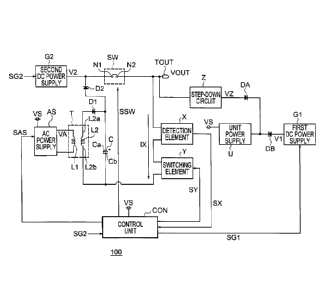
[FIG. 1] FIG. 1 is a diagram illustrating an example
of the
CA 02996871 2018-02-27
9
configuration of a power converting device 100 according to a first
embodiment.
[FIG. 2] FIG. 2 is a diagram illustrating an example of the
configuration of a conventional power converting device 100A.
[Embodiments for Carrying Out the Invention]
[0028]
Embodiments of the present invention will now be described
with reference to the accompanying drawings.
[First Embodiment]
[0029]
FIG. 1 is a diagram illustrating an example of the
configuration of a power converting device 100 according to a first
embodiment. The power converting device 100 according to the
first embodiment converts any of DC voltages outputted from at
least two DC power supplies, and outputs a converted voltage.
[0030]
As shown in FIG. 1, the power converting device 100
includes an AC power supply AS, a first DC power supply G1, a
second DC power supply G2, a transformer T, a detection element
X, a switching element Y, a first rectifier element D1, a second
rectifier element D2, a capacitor C, a switch SW, an output terminal
TOUT, a step-down circuit Z, a control unit CON, a unit power
supply U, a first power supply diode DA, and a second power
supply diode DB.
[0031]
The first DC power supply G1 outputs a first DC voltage V1.
[0032]
The first DC power supply G1 includes a low-voltage battery
that is mounted on a vehicle (not shown), for example, and
outputs the first DC voltage Vi.
[0033]
The AC power supply AS outputs an AC voltage VA.
[0034]
The transformer T includes a primary coil L1 and a
secondary coil L2.
[0035]
=
CA 02996871 2018-02-27
The AC voltage VA outputted from the AC power supply AS
is applied to the primary coil L1 included in the transformer T.
[0036]
As described above, the secondary coil L2 is included in the
5 transformer T, and outputs a voltage obtained by transforming the
AC voltage VA applied to the primary coil L1.
[0037]
The first rectifier element D1 has an end (anode) that is
connected to an end L2a of the secondary coil L2, and another end
10 (cathode) that is connected to an end Ca of the capacitor C. The
first rectifier element D1 is, for example, a first diode with the
anode connected to the end L2a of the secondary coil L2 and the
cathode connected to the end Ca of the capacitor C as shown in
FIG. 1.
[0038]
The capacitor C has the end Ca that is connected to the
other end (cathode) of the first rectifier element D1, and another
end Cb that is connected to another end L2b of the secondary coil
L2.
[0039]
The second DC power supply G2 is configured to output a
second DC voltage V2 that is different from the first DC voltage V1.
The second DC power supply G2 is configured to be activated (to
output the second DC voltage V2) in response to a control signal
SG2.
[0040]
The second DC power supply G2 includes a high-voltage
battery that is mounted on the vehicle, for example, and outputs
the second DC voltage V2. The second DC voltage V2 is set to be
higher than the first DC voltage V1, for example.
[0041]
The output terminal TOUT outputs a first power supply
voltage VOUT.
[0042]
The switch SW includes a first contact Ni connected to the
output of the second DC power supply G2 and a second contact N2
CA 02996871 2018-02-27
11
connected to the output terminal TOUT.
[0043]
The switch SW is turned on to electrically connect the first
contact Ni and the second contact N2, and turned off to electrically
disconnect the first contact Ni and the second contact N2.
[0044]
For example, the switch SW is a contactor or a relay.
[0045]
The second rectifier element D2 has an end (anode) that is
connected to the end Ca of the capacitor C (the other end
(cathode) of the first rectifier element D1) and another end
(cathode) that is connected to the first contact Ni.
[0046]
As shown in FIG. 1, the second rectifier element D2 is, for
example, a second diode with the anode connected to the end Ca
of the capacitor C and the cathode connected to the first contact
Ni of the switch SW.
[0047]
The detection element X is connected between the output
terminal TOUT and the other end Cb of the capacitor C. The
detection element X is configured to output a detection signal SX
based on a detection current IX flowing between the output
terminal TOUT and the end Cb of the capacitor C.
[0048]
The detection element X is an insulation signal transmitting
element for insulation-transmitting the detection signal SX based
on the detection current IX. In this case, the detection element X
is a photocoupler outputting the detection signal SX based on the
detection current IX, for example.
[0049]
The switching element Y is connected in series with the
detection element X between the output terminal TOUT and the
end Cb of the capacitor C.
[0050]
The switching element Y is controlled by a control signal SY.
[0051]
I .
CA 02996871 2018-02-27
12
For example, the switching element Y is turned on in
response to the control signal SY. As a result, the end and the
other end of the switching element Y are electrically connected to
each other to allow the detection current IX to flow. The switching
element Y is also turned off in response to the control signal SY to
disconnect the end and the other end, thereby interrupting the
detection current IX. For example, the switching element Y is a
photo-MOS relay.
[0052]
In a second state where the second DC power supply G2 is
outputting a second DC voltage V2 and the switch SW is in an on
state, the step-down circuit Z outputs a stepped-down voltage VZ
obtained by stepping down the first power supply voltage VOUT of
the output terminal TOUT.
[0053]
The first power supply diode DA has an anode that is
connected to the output of the step-down circuit Z, and a cathode
that is connected to the input of the unit power supply U.
[0054]
The second power supply diode DB has an anode that is
connected to the output of the first DC power supply G1, and a
cathode that is connected to the input of the unit power supply U.
[0055]
The unit power supply U is configured to generate a second
power supply voltage VS from the first DC voltage V1 outputted
from the first DC power supply G1 or the stepped-down voltage VZ
outputted from the step-down circuit Z.
[0056]
For example, the unit power supply U generates and outputs
the second power supply voltage VS from the first DC voltage V1
outputted from the first DC power supply G1 before the second DC
power supply G2 outputs the second DC voltage V2.
[0057]
Alternatively, the unit power supply U generates and outputs
the second power supply voltage VS from the stepped-down
voltage VZ outputted from the step-down circuit Z when the second
=
CA 02996871 2018-02-27
13
DC power supply G2 is outputting the second DC voltage V2 and
the switch SW is in the on state.
[0058]
The control unit CON is supplied with the second power
supply voltage VS to operate.
[0059]
The control unit CON receives the detection signal SX.
Then, the control unit CON controls the operation of the AC power
supply AS with a control signal SAS, the operation of the switching
element Y with the control signal SY, and the operation of the
switch SW with a control signal SSW.
[0060]
For example, the control unit CON is configured to be
activated by the supply of the second power supply voltage VS
generated from the first DC voltage V1, and to activate the AC
power supply AS with the control signal SAS to output the AC
voltage VA.
[0061]
The control unit CON also receives the control signal SG2,
and obtains the operation state of the second DC power supply G2
(in particular, whether the second DC voltage V2 is being
outputted) in response to the control signal SG2.
[0062]
For example, before the second DC power supply G2
outputs the second DC voltage V2, the control unit CON determines
whether the first contact Ni and the second contact N2 of the
switch SW are melted and joined together based on the detection
signal SX.
[0063]
In particular, before the second DC power supply G2 outputs
the second DC voltage V2 and in the first state where the switch
SW is in the off state and the AC power supply AS is outputting the
AC voltage VA, if the detection signal SX that is obtained when the
switching element Y is turned on indicates that the detection
current IX is equal to or above a threshold value, the control unit
CON determines that the first contact Ni and the second contact
CA 02996871 2018-02-27
14
N2 of the switch SW are melted and joined together.
[0064]
In the first state, the second power supply voltage VS is
generated from the first DC voltage V1 by the unit power supply U.
[0065]
If the detection signal SX that is outputted when the
switching element Y is turned on in the first state indicates that the
detection current IX is less than the threshold value, the control
unit CON determines that the first contact Ni and the second
contact N2 of the switch SW are not melted and joined together.
[0066]
If determining that the first contact Ni and the second
contact N2 of the switch SW are melted and joined together, the
control unit CON may prohibit the second DC power supply G2 from
outputting the second DC voltage V2, and maintain the off state of
the switch SW.
[0067]
This prevents the first output terminal TOUT from outputting
an unintended voltage when the first contact Ni and the second
contact N2 of the switch SW are melted and joined together.
[0068]
After determining that the first contact Ni and the second
contact N2 of the switch SW are not melted and joined together,
the control unit CON turns on the switch SW if the second DC
voltage V2 needs to be outputted from the second DC power supply
G2.
[0069]
This helps supply the second DC voltage V2 outputted from
the second DC power supply G2 to the first output terminal TOUT
via the switch SW in the state where the first contact Ni and the
second contact N2 are not melted and joined together and the
switch SW operates normally.
[0070]
When the switch SW is turned on, the control unit CON
turns off the switching element Y.
[0071]
CA 02996871 2018-02-27
This interrupts the detection current IX to reduce power
consumption when the first contact Ni and the second contact N2
are not melted and joined together and the switch SW operates
normally.
5 [0072]
The control unit CON may output a result signal (not shown)
based on the result of determining whether the first contact Ni and
the second contact N2 of the switch SW are melted and joined
together.
10 [0073]
The other elements such as the CPU may obtain information
on whether the first contact Ni and the second contact N2 of the
switch SW are melted and joined together based on the result
signal.
15 [0074]
In the second state where the second DC power supply G2
is outputting the second DC voltage V2 and the switch SW is in the
on state, the unit power supply U generates the second power
supply voltage VS from the stepped-down voltage VZ.
[0075]
As described above, after the control unit CON determines
that the first contact Ni and the second contact N2 of the switch
SW are not melted and joined together, and if the second DC
voltage V2 needs to be outputted from the second DC power supply
G2, the control unit CON outputs the control signal SSW to turn on
the switch SW. At this time, the control unit CON turns on the
switching element Y. If the detection signal SX that is outputted
when the switching element Y is turned on indicates that the
detection current IX is less than the threshold value (no signal is
outputted), the control unit CON determines that the switch SW
has not been brought into the on state by the control signal SSW.
Based on this determination result, the control unit CON may
output a signal indicating that the switch SW cannot be normally
controlled, for example.
[0076]
Next, an example of the operation of the power converting
CA 02996871 2018-02-27
16
device 100 having the above described configuration will be
described below.
[0077]
For example, the control unit CON is activated by the supply
of the second power supply voltage VS generated by the first DC
voltage V1, and then activates the AC power supply AS with the
control signal SAS to output the AC voltage VA.
[0078]
The control unit CON then receives the control signal SG2
and, in response to the control signal SG2, obtains the operation
state of the second DC power supply G2 (in particular, whether the
second DC voltage V2 is being outputted).
[0079]
The control unit CON then turns on the switching element Y
with the control signal SY before the second DC power supply G2
outputs the second DC voltage V2. Thereafter, the control unit
CON determines whether the first contact Ni and the second
contact N2 of the switch SW are melted and joined together based
on the detection signal SX outputted by the detection element X.
[0080]
In particular, before the second DC power supply G2 outputs
the second DC voltage V2 and in the first state where the switch
SW is in the off state and the AC power supply AS is outputting the
AC voltage VA, the control unit CON determines that the first
contact Ni and the second contact N2 of the switch SW are melted
and joined together if the detection signal SX that is outputted
when the switching element Y is turned on indicates that the
detection current IX is equal to or more than the predefined
threshold value.
[0081]
If the detection signal SX that is outputted when the
switching element Y is turned on indicates that the detection
current IX is less than the threshold value in the first state, the
control unit CON determines that the first contact Ni and the
second contact N2 of the switch SW are not melted and joined
together.
. .
CA 02996871 2018-02-27
,
17
[0082]
According to the above operation, the control unit CON may
determine whether the first contact Ni and the second contact N2
of the switch SW are melted and joined together before the first
power supply voltage VOUT is outputted from the first output
terminal TOUT via the switch SW.
[0083]
As described above, a power converting device according to
an aspect of the present invention includes a first DC power supply
configured to output a first DC voltage, an AC power supply
configured to output an AC voltage, a primary coil included in a
transformer to which the AC voltage outputted by the AC power
supply is applied, a secondary coil included in the transformer, a
first rectifier element having an end that is connected to an end of
the secondary coil, a capacitor having an end that is connected to
another end of the first rectifier element, and another end that is
connected to another end of the secondary coil, a second DC power
supply configured to output a second DC voltage that is different
from the first DC voltage, a switch including a first contact
connected to an output of the second DC power supply, and a
second contact connected to an output terminal that outputs a first
power supply voltage, the switch being turned on to electrically
connect the first contact and the second contact, and turned off to
electrically disconnect the first contact and the second contact, a
second rectifier element having an end that is connected to the end
of the capacitor and another end that is connected to the first
contact, a detection element connected between the output
terminal and the other end of the capacitor, and outputs a
detection signal based on a detection current flowing through the
output terminal and the other end of the capacitor, a switching
element connected in series with the detection element between
the output terminal and the other end of the capacitor, and a
control unit that is supplied with a second power supply voltage to
operate, receives a detection signal, and controls operations of the
AC power supply, the switching element, and the switch.
[0084]
r
CA 02996871 2018-02-27
18
Before the second DC power supply outputs the second DC
voltage, the control unit determines whether the first contact and
the second contact of the switch are melted and joined together
based on the detection signal.
[0085]
More specifically, before the second DC power supply
outputs the second DC voltage and in a first state where the switch
is in an off state and the AC power supply is outputting the AC
voltage, the control unit determines that the first contact and the
second contact of the switch are melted and joined together if the
detection signal outputted when the switching element is turned on
indicates that the detection current is equal to or more than a
threshold value that is predefined. On the other hand, the control
unit determines that the first contact and the second contact of the
switch are not melted and joined together if, in the first state, the
detection signal outputted when the switching element is turned on
indicates that the detection current is less than the threshold value.
[0086]
Thus, whether the contacts of the switch are melted and
joined together may be detected before the first power supply
voltage is outputted via the switch based on the second DC voltage
outputted from the second DC power supply.
[0087]
If, for example, the control unit determines that the first
contact and the second contact of the switch are melted and joined
together, the control unit may prevent an unintended output of the
power supply voltage by prohibiting the second DC power supply
from outputting the second DC voltage, and maintaining the off
state of the switch.
[0088]
While certain embodiments have been described, these
embodiments have been presented by way of example only, and
are not intended to limit the scope of the inventions.
The
embodiments may be embodied in a variety of other forms.
Furthermore, various omissions, substitutions and changes in the
form of the methods and systems described herein may be made
1
CA 02996871 2018-02-27
19
without departing from the spirit of the inventions. The
embodiments and their modifications are included in the scope and
the subject matter of the invention, and at the same time included
in the scope of the claimed inventions and their equivalents.