Note: Descriptions are shown in the official language in which they were submitted.
SYSTEMS AND METHODS FOR SHORT LOOP REGENERATION OF GAS
DEHYDRATION UNITS
FIELD
The present disclosure relates to the field of gas dehydration units that
utilize adsorption
beds containing molecular sieve, and further relates to systems and methods
for regenerating the
adsorption beds in such gas dehydration units. The gas is then subjected to
cryogenic cooling to
form liquefied gas.
BACKGROUND
In conventional natural gas conditioning, natural gas, having passed through
an acid gas
removal unit (AGRU) and dewpoint control, is often dehydrated by passing the
natural gas
through a system of vessels or units referred to as a dehydration unit
including adsorption beds
made up of molecular sieve particulate material, also referred to as mole
sieve. Such a system
includes at least two vessels in which one of the vessels contains saturated
molecular sieve that
is in regeneration mode, while the other one or more vessels are operated in
dehydration or
adsorption mode. During dehydration mode, water is adsorbed onto the molecular
sieve
material; and during regeneration mode, water is desorbed from the molecular
sieve. Typically,
the regeneration is effected by passing hot dry natural gas, i.e., natural gas
having been
dehydrated, over the saturated molecular sieve. This requires a large
compressor to return hot
dry natural gas to a location upstream of the AGRU upstream of the dehydration
unit.
Dehydration of natural gas is typically accomplished by flowing the gas over
zeolite-
based molecular sieve adsorbent. Water in the gas is preferentially adsorbed
by the molecular
sieve. Removal of water from the gas using molecular sieve dehydration is a
vital process
component in any liquefied natural gas (LNG) plant to meet moisture content
specifications
(down to 0.1 ppmv). Natural gas can contain additional contaminants such as
hydrogen sulfide,
mercaptans, carbonyl sulfide, etc. that are partially co-adsorbed by the
molecular sieve. During
high pressure regeneration, system design problems can result in water and
hydrocarbon
refluxing, poor water desorption, and high residual water content within the
molecular sieve
1
CA 2996926 2018-02-28
after regeneration. This can result in early moisture breakthrough and
economic losses
associated with frequent molecular sieve change outs and low dehydrator
availability
During regeneration, a regeneration gas can be used to heat the molecular
sieve bed to
desorb water. If the molecular sieve bed is regenerated at high temperature
and low pressure,
then the regeneration gas may be a slip stream of dry gas, storage tank boil
off gas, or any other
suitable dry gases. If the regeneration is conducted at high pressure and
large vessel diameters,
then the vessel thickness and choice of materials will create additional heat
load on the
regeneration system. In addition, the high operating regeneration pressure can
result in water and
hydrocarbon refluxing and lower desorption rate and efficiency.
The regeneration gas may contain contaminants such as oxygen that reacts with
hydrogen, hydrogen sulfide and/or hydrocarbon (e.g. propane) at high
regeneration temperatures
resulting in the formation of unwanted by-products such as sulfur, sulfur di-
oxides, water and
carbon dioxide. These by-products can build up in downstream units, or in the
fuel system
causing problems such as fouling, and off-specification products. Furthermore,
the complete
regeneration of molecular sieves is not achieved because of the contaminants
present resulting in
sub-optimal performance of the dehydration unit. This may also be accompanied
by damage
caused to the molecular sieve resulting in reduced operating life. One known
solution is further
purification of the regeneration gas by using additional adsorbents. However,
such schemes are
expensive and will not always result in full contaminant removal of the
regeneration gas.
Referring to FIG. 1, dehydration of a gas such as natural gas feed stream 1 is
typically
done by flowing a wet gas 23 over a bed of zeolite-based molecular sieve
adsorbent material
(not shown) in a vessel 2A. As a result the molecular sieve adsorbent material
becomes saturated
with water and must be regenerated after a period of use. The adsorbent is
regenerated in vessel
2R at high temperature by flowing dry regeneration gas 3, which is typically a
slip stream of
dried process gas 4, over the bed of molecular sieve adsorbent material. The
regeneration gas is
then cooled in a condenser 5, free water 6 is separated in a separator 11 and
removed, and the
remaining gas 7 is compressed by a compressor 8 and returned through line 46
to the front-end
of the plant, upstream of the acid gas removal unit 9 which also receives the
feed gas 1. The
quantity of regeneration gas 3 available is limited by the capacity of the
recycle compressor 8,
regeneration gas heater 10, regeneration gas cooler (also referred to as
condenser) 5 and the
capacity of the front-end equipment in the system including the acid gas
removal unit 9. If there
2
CA 2996926 2018-02-28
are any problems with the dehydration unit not being able to meet dried gas
specifications, very
little can be done to improve the regeneration of the molecular sieves due to
these overall system
constraints.
There exists a need for a more robust, more flexible and less costly method
and system
for regenerating saturated molecular sieve in a gas dehydration unit,
particularly which increase
the availability of regeneration gas.
SUMMARY
In one aspect, a system is provided for dehydrating a gas feed stream in a
system to
produce liquefied natural gas, liquefied petroleum gas, or cryogenic gas. At
least two vessels are
arranged in parallel for containing molecular sieve material for adsorbing
water from a gas feed
stream passed over the molecular sieve material. Each of the at least two
vessels has two ends
wherein each end has an opening and wherein each opening can act as a vessel
inlet or a vessel
outlet depending on a direction of fluid flow through each of the at least two
vessels. One of the
at least two vessels is in regeneration mode and the other(s) of the at least
two vessels is(are) in
adsorption mode at a given time during a cycle in which the vessel in
regeneration mode
alternates among the at least two vessels. The vessel in regeneration mode has
a regeneration gas
inlet and a regeneration gas outlet and the vessel(s) in adsorption mode each
have a feed gas
inlet and a dried gas outlet. Gas from an acid gas removal unit is fed into
the feed gas inlet(s) of
the vessel(s) in adsorption mode. Dried gas leaves the dried gas outlet(s) of
the vessel(s) in
adsorption mode to be further processed in a liquefied natural gas, liquefied
petroleum gas, or
cryogenic gas plant. A conduit is in communication with the dried gas
outlet(s) of the vessel(s)
in adsorption mode for passing a slip stream of the dried gas to the
regeneration gas inlet of the
vessel in regeneration mode such that the slip stream is used as a
regeneration gas for passing
over and thereby desorbing water from the molecular sieve material within the
vessel in
regeneration mode. A heater heats the regeneration gas prior to passing the
regeneration gas to
the vessel in regeneration mode to a temperature sufficient to desorb the
water from the
molecular sieve material. A condenser in communication with the regeneration
gas outlet of the
vessel in regeneration mode is used to form a stream containing condensed
water and gas. A
separator separates the stream into a water stream and a regeneration gas
stream. A compressor
compresses the regeneration gas stream. A conduit is used for passing the
regeneration gas
3
CA 2996926 2018-02-28
stream from the compressor to a location upstream of the heater for heating
the regeneration gas
stream to the temperature sufficient to desorb the water from the molecular
sieve material.
In one aspect, a method is provided for dehydrating the gas feed stream using
the system
described above. The vessel in regeneration mode remains in regeneration mode
until the water
has been sufficiently desorbed from the molecular sieve material.
In accordance with another aspect, there is a system for dehydrating a gas
feed stream in
a system to produce liquefied natural gas, liquefied petroleum gas, or
cryogenic gas, comprising:
a. at least two vessels arranged in parallel for containing
molecular sieve material
for adsorbing water from a gas feed stream passed over the molecular sieve
material
wherein:
i. each of the at least two vessels has two ends wherein
each end has an
opening and wherein each opening can act as a vessel inlet or a vessel
outlet depending on a direction of fluid flow through each of the at least
two vessels;
ii. one of the at least two vessels is in regeneration mode and the
other(s) of
the at least two vessels is(are) in adsorption mode at a given time during a
cycle in which the vessel in regeneration mode alternates among the at
least two vessels;
iii. the vessel in regeneration mode has a regeneration gas inlet and a
regeneration gas outlet and the vessel(s) in adsorption mode each have a
feed gas inlet and a dried gas outlet;
iv. gas from an acid gas removal unit is fed into the feed gas inlet(s) of
the
vessel(s) in adsorption mode; and
v. dried gas leaves the dried gas outlet(s) of the vessel(s) in adsorption
mode
to be further processed in a liquefied natural gas, liquefied petroleum gas,
or cryogenic gas plant;
b. a conduit in communication with the dried gas outlet(s) of the
vessel(s) in
adsorption mode for passing a slip stream of the dried gas to the regeneration
gas inlet of
the vessel in regeneration mode such that the slip stream is used as a
regeneration gas for
passing over and thereby desorbing water from the molecular sieve material
within the
vessel in regeneration mode;
4
Date Recue/Date Received 2023-05-17
c. a heater for heating the regeneration gas prior to passing the
regeneration gas to
the vessel in regeneration mode to a temperature sufficient to desorb the
water from the
molecular sieve material;
d. a condenser in communication with the regeneration gas outlet of the
vessel in
regeneration mode for condensing water in an overhead stream from the
regeneration gas
outlet to form a stream containing water and gas;
e. a separator for separating the water and the gas from the stream
containing water
and gas thereby forniing a water stream and a regeneration gas stream;
f. a compressor for compressing the stream of regeneration gas stream; and
g- a conduit for passing the regeneration gas stream from the compressor to
a
location upstream of the heater such that the regeneration gas stream can be
heated to the
temperature sufficient to desorb the water from the molecular sieve material.
In another aspect, there is a method for regenerating a molecular sieve bed in
a
dehydration unit for dehydrating a gas feed stream in a system to produce
liquefied natural gas,
liquefied petroleum gas, or cryogenic gas wherein the gas dehydration unit
comprises at least
two vessels arranged in parallel for containing molecular sieve material for
adsorbing water
from a gas feed stream passed over the molecular sieve material wherein each
of the at least two
vessels has two ends wherein each end has an opening and wherein each opening
can act as a
vessel inlet or a vessel outlet depending on a direction of fluid flow through
each of the at least
two vessels one of the at least two vessels is in regeneration mode and the
other(s) of the at least
two vessels is(are) in adsorption mode at a given time during a cycle in which
the vessel in
regeneration mode alternates among the at least two vessels; the vessel in
regeneration mode has
a regeneration gas inlet and a regeneration gas outlet and the vessel(s) in
adsorption mode each
have a feed gas inlet and a dried gas outlet; gas from an acid gas removal
unit is fed into the feed
gas inlet(s) of the vessel(s) in adsorption mode; and dried gas leaves the
dried gas outlet(s) of the
vessel(s) in adsorption mode to be further processed in a liquefied natural
gas or cryogenic gas
plant; the method comprising:
a. passing a slip stream of the dried gas from the dried gas outlet(s) of
the vessel(s)
in adsorption mode to the regeneration gas inlet of the vessel in regeneration
mode such
that the slip stream is used as a regeneration gas for passing over and
thereby desorbing
water from the molecular sieve material within the vessel in regeneration
mode;
b. heating the regeneration gas prior to passing the regeneration gas to
the
regeneration gas inlet of the vessel in regeneration mode to a temperature
sufficient to
desorb the water from the molecular sieve material;
4a
Date Recue/Date Received 2023-05-17
c. condensing water in an overhead stream from the regeneration gas outlet
of the
vessel in regeneration mode to form a stream containing water and gas;
d. separating the water and the gas from the stream thereby forming a water
stream
and a regeneration gas stream;
e. compressing the regeneration gas stream;
f. recycling the regeneration gas stream from the compressor to a
location upstream
of the heater;
g- heating the regeneration gas stream to the temperature
sufficient to desorb the
water from the molecular sieve material;
h. passing the regeneration gas stream over and thereby desorbing water
from the
molecular sieve material within the vessel in regeneration mode; and
i. repeating steps (c) through (h) until the desorbing of water
from the molecular
sieve material within the vessel in regeneration mode is sufficiently
complete.
DESCRIPTION OF THF, DRAWINGS
These and other objects, features and advantages of the present invention will
become
better understood with reference to the following description, appended claims
and
accompanying drawings. The drawings are not considered limiting of the scope
of the appended
claims. The elements shown in the drawings are not necessarily to scale.
Reference numerals
designate like or corresponding, but not necessarily identical, elements.
FIG. 1 is a simplified schematic diagram illustrating a gas dehydration unit
according to
the prior art.
FIGS. 2-3 are schematic diagrams illustrating gas dehydration units according
to
exemplary embodiments.
DETAILED DESCRIPTION
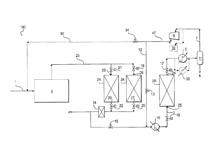
In one embodiment, referring to FIG. 2, a system 100 and its operation for
regenerating
water saturated molecular sieve in a gas dehydration unit used in a process
for dehydrating a gas
feed stream 1 will now be described. The gas dehydration unit is used in a
system to produce
liquefied natural gas, liquefied petroleum gas, or cryogenic gas. The gas
dehydration unit
includes at least two adsorbent bed containing vessels (2A, 2A and 2R)
arranged in parallel. In
one embodiment, as shown, the system comprises three vessels arranged in
parallel. Four or
more vessels could also be used. As shown, those vessels in adsorption mode
also referred to as
dehydration mode are labeled 2A while those vessels in regeneration mode are
labeled 2R. At
any given time, one of the at least two vessels is in regeneration mode and
the other(s) of the at
4b
Date Recue/Date Received 2023-05-17
least two vessels is (are) in adsorption mode. The vessel in regeneration mode
alternates among
each of the at least two vessels in a complete cycle. The vessel in
regeneration mode 2R has a
regeneration gas inlet 25 and a regeneration gas outlet 24, and the vessel(s)
in adsorption mode
2A each have a feed gas inlet (28, 26) and a dried gas outlet (22, 20).
4c
Date Recue/Date Received 2023-05-17
Vessels 2A are shown in dehydration mode or adsorption mode, such that
moisture
containing gas 23 enters at the top of the vessels and dehydrated gas 4 exits
at the bottom of the
vessels. The moisture containing gas 23 may be provided from an acid gas
removal unit
(AGRU) 9 is fed into the feed gas inlet(s) of the vessel(s) 2A in adsorption
mode.
Vessel 2R in regeneration mode contains saturated molecular sieve material. As
shown,
vessel 2R has a regeneration gas inlet 25 at the bottom thereof, and a
regeneration gas outlet 24
at the top thereof. In some embodiments (not shown), vessel 2R can have the
regeneration gas
inlet at the top of the vessel and the regeneration gas outlet at the bottom
of the vessel, as would
be apparent to one of ordinary skill in the art. Each of the at least two
vessels has two ends
wherein each end has an opening therein. Each opening acts as either a vessel
inlet or a vessel
outlet depending on the direction of fluid flow through the vessel. In one
embodiment, a valve is
located proximate and in fluid communication with each of the two ends of the
vessels for
controlling flow to and from the opening, acting as either a vessel inlet or
vessel outlet. As
shown, the vessel 2R has an upper opening 24 with valve 17 located proximate
opening 24, and
a lower opening 25 with valve 18 proximate opening 25. Similarly, vessels 2A
have upper
openings 28 and 26, respectively and valves 21 and 19, respectively, and lower
openings 29 and
27, respectively and valves 22 and 20, respectively.
Dehydrated gas is filtered in filter 14. As in the prior art system shown in
FIG. 1,
dehydration of a gas (such as, but not limited to natural gas) feed stream 1
is typically done by
flowing a water-containing gas 23 to be dehydrated over a bed of zeolite-based
molecular sieve
adsorbent material, also referred to as molecular sieve material (not shown),
in a vessel 2A, such
that the molecular sieve material adsorbs water from a water-containing gas
stream passed over
the molecular sieve material. Dried gas leaves the dried gas outlet(s) of the
vessel(s) in
adsorption mode to be further processed in a liquefied natural gas, liquefied
petroleum gas, or
cryogenic gas plant.
After a period of use, the molecular sieve adsorbent material becomes
saturated with
water and must be regenerated for a period of time to remove the water.
Following regeneration,
the molecular sieve material is typically cooled prior to returning the
molecular sieve material to
service in adsorption mode.
The adsorbent is regenerated in vessel 2R at high temperature by flowing a
regeneration
gas 3 over the bed of molecular sieve adsorbent material in vessel 2R. The
regeneration gas 3 is
typically initiated by taking a slip stream of filtered dried process gas 4
using valve 15 in a
conduit in communication with the dried gas outlet(s) 22, 20 of the vessel(s)
in adsorption mode
5
CA 2996926 2018-02-28
2A. The regeneration gas 3 is heated in heater 10 to a temperature sufficient
to desorb water
from the saturated molecular sieve and is passed to the regeneration gas inlet
25 of the vessel in
regeneration mode 2R such that the slip stream is used as a regeneration gas
for passing over and
thereby desorbing water from the molecular sieve material within the vessel
2R.
The regeneration gas then leaves the vessel 2R and is cooled in a condenser 5
in
communication with the regeneration gas outlet 24 of the vessel 2R for cooling
an overhead
stream from the regeneration gas outlet 24 to form a stream containing water
and gas.
Optionally, an additional condenser 33 can also be provided as needed. The
stream passes to a
separator (also referred to as a knock out drum) 11 where free water 6 is
separated and removed
and a gas stream 7 also referred to as the regeneration gas stream is formed.
The regeneration
gas stream 7 is then compressed by a compressor 8. Optionally, an additional
compressor 32 can
also be provided as needed.
Rather than returning the compressed regeneration gas stream through line 46
to the
front-end of the plant, upstream of the acid gas removal unit 9, also referred
to as the "long
loop," the compressed regeneration gas stream is instead directed through a
"short loop" by
directing the gas through a section of conduit 12 (and conduit 47 in the
scheme as shown) to a
location upstream of regeneration gas heater 10 prior to being fed to the
regeneration gas inlet
25. The long loop is the same as the current path of compressed regeneration
gas labeled as 46 in
FIG. I. Valve 13 is provided in conduit 12 for controlling flow through the
short loop. The
regeneration gas will be recycled and recirculated within the short loop by
the compressor 8 and
continued to be used to regenerate the molecular sieve in vessel 2R until the
desorbing of water
from the molecular sieve material within vessel 2R is sufficiently complete,
i.e., until the
molecular sieve has been adequately regenerated such that it is ready to be
returned to service in
adsorption mode.
Thus, in one embodiment, system 100 regenerates the molecular sieve in vessel
2R
through a process of bulk regeneration in which a large flow of water-
saturated gas passes
through the short loop consisting of the vessel 2R, a condenser 5, a separator
11, a compressor 8,
and piping 47 and 12 to direct the compressed regeneration gas to the heater
10 upstream of the
regeneration gas inlet 25 of vessel 2R.
As the gas no longer flows through the front-end of the plant (i.e., the long
loop), the
regeneration gas flow in this circuit (i.e., the short loop) can
advantageously be increased, as it is
not limited by the front-end capacity of the plant viz. the AGRU 9. Moreover,
as the gas does
not flow back to the front-end, the pressure of the system during regeneration
can be reduced
6
CA 2996926 2018-02-28
within the limits of system hydraulics. The compressed regeneration gas, also
referred to herein
as the regeneration gas stream, though not completely dry, will have a much
higher actual
volumetric flow rate through the molecular sieve bed of vessel 2R which will
provide improved
heat and mass transfer and thereby effectively desorb a significant quantity
of water and other
contaminants adsorbed on the molecular sieve bed.
In one embodiment, system 100 further includes a conduit 30 for passing the
regeneration gas stream from the compressor to a location upstream of the AGRU
9. In this
embodiment, the process of bulk regeneration is followed by an optional
polishing step using a
lower volumetric flow (relative to the flow rate used in the short loop) of
completely dry gas in
the long loop. As shown in FIG. 2, the long loop consists of piping 47 and 30
to direct
regeneration gas to a location upstream of the AGRU 9. A valve 34 is provided
to control flow
into the line 30. The optional polishing can achieve complete water removal
and cooling of the
molecular sieve bed.
As mentioned, following regeneration of a vessel, the vessel is typically
cooled. In the
cooling step, regeneration gas follows nearly the same path as during
regeneration, except that
the regeneration gas bypasses the heater, such that cool regeneration gas is
passed into the
molecular sieve bed to return it to a temperature that is appropriate for
adsorption.
LNG plants have been known to experience performance and reliability issues in
their
molecular sieve dehydration units. The embodiments disclosed herein are
intended to de-
.. bottleneck such molecular sieve regeneration issues. For example, if a
designed regeneration gas
flow rate is insufficient given the size of the vessels 2A and 2R, radial heat
transfer to the vessel
walls is limited, resulting in an excessive amount of time to regenerate the
outer portions of the
bed. Ultimately, this limits the flow rate through the molecular sieves and
overall LNG
production. The use of the embodiments disclosed herein would advantageously
address such
issues by significantly increasing the regeneration gas flow rate, which will
improve heat
transfer throughout the bed and result in more effective regeneration. By
separating the
regeneration process into a short loop and long loop cycle, the total time
required for
regeneration can also be reduced. This will improve the molecular sieve
dehydrator performance
and allow for more LNG throughput. The embodiments disclosed herein can be
used in future
new designs, to reduce capital expense, operating expense and improve
reliability. Capital
expense can be reduced by potentially reducing the number of beds required as
a result of the
shortened cycle times. Existing plants can also be retrofitted to implement
the embodiments
disclosed herein to address underperforming or bottlenecked dehydration units.
Additionally, the
7
CA 2996926 2018-02-28
embodiments disclosed herein enable regeneration at lower pressures resulting
in more effective
regeneration. Lower pressure regeneration enables better gas distribution
through the molecular
sieve bed, resulting in reduced residual water content.
In one embodiment, heat generated by the recycle compressor 8 can be utilized
to
increase the heating capacity of the circulating regeneration gas.
In one embodiment, contaminant buildup in the system can be reduced as water 6
is
removed from the separator 11. At high regeneration temperatures, mercaptans
will decompose
to I-12S and oxygen will react away with the hydrocarbons.
In one embodiment, referring to FIG. 3, an alternative system 200 and its
operation for
regenerating water saturated molecular sieve in a gas dehydration unit will
now be described.
System 200 is similar to system 100 with the addition of an optional second
dehydration unit for
further removing moisture from the regeneration gas stream. The second
dehydration unit
includes a pair of vessels 37 and 38 arranged in parallel and containing
molecular sieve material.
The pair of vessels 37 and 38 alternate between absorption and regeneration
modes. As shown in
FIG. 3, vessel 37 is in adsorption mode and vessel 38 is in regeneration mode.
Vessel 37 is
located in the short loop located between conduit 12 and conduit 43 for
passing the regeneration
gas stream from the compressor 8 to a location upstream of the heater 10.
Vessel 38 is located in
the short loop between conduit 44 and conduit 35. Vessels 37 and 38 are
smaller than vessels 2A
and 2R. In one nonlimiting example, the primary larger dehydration vessels 2A
and 2R have an
inner diameter of about 5 meters and tangent-to-tangent height of about 9
meters. The secondary
smaller dehydration vessels 37 and 38 have an inner diameter of about 3 meters
and tangent-to-
tangent height of about 7 meters. In this example, each smaller dehydrator
vessel has a bed
volume that is roughly 25% of the larger dehydrator bed volume.
Each of vessels 37 and 38 have openings at each end thereof, as shown vessel
37 has
openings 39 and 40, and vessel 38 has openings 41 and 42, which openings act
as inlets or
outlets depending on the direction of flow. A valve 45 can be provided in the
conduit 42 for
controlling flow between vessel 38 and a location upstream of heater 10.
Likewise, a valve 46 in
a conduit 36 can be provided to control flow between vessel 38 and a location
downstream of
heater 10. Other valving and piping will be present as would be apparent to
one of ordinary skill
in the art. Prior to passing the regeneration gas stream to the regeneration
gas inlet 25 of vessel
2R, the regeneration gas stream is passed through the second dehydration unit
(i.e., vessel 37 of
8
CA 2996926 2018-02-28
the pair of vessels 37 and 38), thereby further removing moisture from the
regeneration gas
stream. Thus system 200 regenerates the molecular sieves in a short loop using
regeneration gas
that has been completely dried by a smaller molecular sieve unit.
When vessel 38 is in regeneration mode, heated regeneration gas is taken from
downstream of the heater 10. Additionally, during regeneration mode, some
amount of unheated
regeneration gas taken from upstream of the heater 10 can be mixed with the
heated regeneration
gas to control the regeneration gas temperature, thus providing operational
flexibility to
regenerate vessel 38 at a lower temperature than vessel 2R. After having been
regenerated,
vessel 38 can be cooled using unheated regeneration gas taken from upstream of
the heater 10.
Conduit 36 is the piping through which a slip stream of hot regeneration gas
flows when the
dehydrator vessel 38 is in regeneration mode. The flow is controlled by
control valve 46. When
dehydrator vessel 38 goes into regeneration mode required heated gas, valve 46
opens. When
dehydrator vessel 38 goes into cooling mode following regeneration, valve 46
closes, and valve
45 opens so unheated regeneration gas flows through the dehydrator vessel 38.
In the embodiment shown in FIG. 3, the regeneration gas from the compressor(s)
8 is
not sent back to the front-end of the plant, i.e. to AGRU 9. Instead, the
regeneration gas is
diverted to the smaller vessels 37 and 38, one in adsorption and one in
regeneration modes. The
smaller vessel in adsorption 37 removes the remaining moisture so that the
regeneration gas is
rendered completely dry. This dry gas is then heated in heater 10 and is used
to regenerate the
existing molecular sieve bed in vessel 2R. To regenerate the smaller vessel in
adsorption 37, a
slip stream is taken from either upstream or downstream of the heater 10
(depending on whether
the vessel 2R is in heating or cooling). Use of the short loop as shown does
not involve recycling
gas back to the AGRU 9. This results in greater operational flexibility and
higher possible LNG
throughput.
Advantages of the embodiment shown in FIG. 3 include the following. The
regeneration
gas is completely dry throughout the entire regeneration cycle, so that the
regeneration time can
be further reduced, beyond the regeneration time reduction of the embodiment
shown in FIG. 2.
The short loop operates independently of the AGRU 9. No regeneration gas is
recycled back to
the front-end of the plant, so the feed flow rate and LNG throughput can be
increased
accordingly.
In embodiments in which no recycle stream passes back to the AGRU 9, smaller
equipment sizes can potentially be used for the AGRU 9 and associated
equipment.
9
CA 2996926 2018-02-28
Disclosed herein are various embodiments of short loop regeneration systems
and
methods. The embodiments disclosed herein are intended to be used in new gas
plants or in
retrofits of existing gas plants, particularly those having an inadequate
regeneration system in
which regeneration gas flow rate and contamination issues are concerns.
It should be noted that only the components relevant to the disclosure are
shown in the
figures, and that many other components normally part of a gas dehydration
system are not
shown for simplicity.
For the purposes of this specification and appended claims, unless otherwise
indicated,
all numbers expressing quantities, percentages or proportions, and other
numerical values used
1.0 in the specification and claims are to be understood as being modified
in all instances by the
term "about." Accordingly, unless indicated to the contrary, the numerical
parameters set forth in
the following specification and attached claims are approximations that can
vary depending
upon the desired properties sought to be obtained by the present invention. It
is noted that, as
used in this specification and the appended claims, the singular forms "a,"
"an," and "the,"
include plural references unless expressly and unequivocally limited to one
referent.
Unless otherwise specified, the recitation of a genus of elements, materials
or other
components, from which an individual component or mixture of components can be
selected, is
intended to include all possible sub-generic combinations of the listed
components and mixtures
thereof. Also, "comprise," "include" and its variants, are intended to be non-
limiting, such that
recitation of items in a list is not to the exclusion of other like items that
may also be useful in
the materials, compositions, methods and systems of this invention.
This written description uses examples to disclose the invention, including
the best
mode, and also to enable any person skilled in the art to make and use the
invention. The
patentable scope is defined by the claims, and can include other examples that
occur to those
skilled in the art. Such other examples are intended to be within the scope of
the claims if they
have structural elements that do not differ from the literal language of the
claims, or if they
include equivalent structural elements with insubstantial differences from the
literal languages of
the claims.
From the above description, those skilled in the art will perceive
improvements, changes and
modifications, which are intended to be covered by the appended claims.
Date Recue/Date Received 2023-05-17