Note: Descriptions are shown in the official language in which they were submitted.
CA 02997232 2018-03-01
DESCRIPTION
VEHICLE TRAVELING CONTROL METHOD AND VEHICLE TRAVELING
CONTROL DEVICE
Technical Field
[0001]
The present invention relates to a vehicle traveling
control method and a vehicle traveling control device.
Background Art
[0002]
An automatic start/stop device is described in PTL 1,
which device has a control means for not only controlling an
engine so as to be automatically stopped when an predetermined
automatic stop condition for deceleration status is satisfied,
the condition being such that required torque is small with
respect to running resistance during the operation of the
engine, but also controlling a start clutch so as to be
disconnected when a clutch disconnection condition is
satisfied after the automatic stop of the engine.
Citation List
Patent Literature
[0003]
PTL 1: JP H07-266932 A
- 1 -
Summary of Invention
Technical Problem
[0004]
Inertial traveling during which a vehicle travels, with
its clutch for transmitting power between its engine and drive
wheels disconnected, cannot input the rotational driving force
of its drive wheels to its electric motor, and therefore,
deceleration energy regeneration cannot be performed. For this
reason, when the duration of inertial traveling is short, the
loss of deceleration energy owing to the impossibility of its
regeneration may exceeds a fuel consumption reduction effect
thanks to inertial traveling, thereby resulting in worsened
fuel efficiency.
An object of the present invention is to reduce fuel
efficiency deterioration caused by the impossibility of
deceleration energy regeneration owing to inertial traveling.
Solution to Problem
[0005]
According to an aspect of the present invention, there is
provided a vehicle traveling control method comprising:
determining a driver's intention for acceleration during
vehicle traveling;
predicting, when it is determined that the driver has no
intention for acceleration, which is superior between a first
fuel consumption reduction effect by inertial traveling and a
second fuel consumption reduction effect by deceleration
energy regeneration, the inertial traveling making the vehicle
travel, with power transmission disconnected between an engine
- 2 -
Date recue / Date received 2021-11-29
and a drive wheel of the vehicle, and the deceleration energy
regeneration inputting rotational power of the drive wheel of
the vehicle to an electric motor;
performing inertial traveling when it is predicted that
the first fuel consumption reduction effect by inertial
traveling is superior to the second fuel consumption reduction
effect by deceleration energy regeneration;
performing deceleration energy regeneration when it is
predicted that the first fuel consumption reduction effect by
inertial traveling is not superior to the second fuel
consumption reduction effect by deceleration energy
regeneration;
detecting a speed of the vehicle upon determining that
the driver has no intention for acceleration; and
predicting, when the speed is equal to or higher than a
speed threshold, that the first fuel consumption reduction
effect by inertial traveling is superior to the second fuel
consumption reduction effect by deceleration energy
regeneration, and when the speed is less than the speed
threshold, that the first fuel consumption reduction effect by
inertial traveling is not superior to the second fuel
consumption reduction effect by deceleration energy
regeneration.
According to another aspect of the present invention,
there is provided a vehicle traveling control method
comprising:
¨ 3 ¨
Date recue / Date received 2021-11-29
determining a driver's intention for acceleration during
vehicle traveling;
predicting, when it is determined that the driver has no
intention for acceleration, which is superior between a first
fuel consumption reduction effect by inertial traveling and a
second fuel consumption reduction effect by deceleration
energy regeneration, the inertial traveling making the vehicle
travel, with power transmission disconnected between an engine
and a drive wheel of the vehicle, and the deceleration energy
regeneration inputting rotational power of the drive wheel of
the vehicle to an electric motor;
performing inertial traveling when it is predicted that
the first fuel consumption reduction effect by inertial
traveling is superior to the second fuel consumption reduction
effect by deceleration energy regeneration;
performing deceleration energy regeneration when it is
predicted that the first fuel consumption reduction effect by
inertial traveling is not superior to the second fuel
consumption reduction effect by deceleration energy
regeneration;
detecting a distance and a relative speed between the
vehicle and an object which can be a stopping factor for
inertial traveling, upon determining that the driver has no
intention for acceleration; and
predicting, according to the distance and the relative
speed, whether or not the first fuel consumption reduction
effect by inertial traveling is superior to the second fuel
consumption reduction effect by deceleration energy
regeneration.
-3a-
Date recue / Date received 2021-11-29
According to a further aspect of the present invention,
there is provided a vehicle traveling control device
including:
an accelerator depression degree detection device
configured to detect accelerator depression degree by a
driver; and
a control device configured to control an electric motor
and a clutch for transmitting power between an engine and a
drive wheel and between the electric motor and the drive
wheel,
wherein when the accelerator depression degree is no
longer detected, the control device predicts which is superior
between a first fuel consumption reduction effect by inertial
traveling and a second fuel consumption reduction effect by
deceleration energy regeneration, the inertial traveling
making the vehicle travel, with power transmission
disconnected between the engine and the drive wheel, and the
deceleration energy regeneration inputting rotational power of
the drive wheel to the electric motor,
when it is predicted that the first fuel consumption
reduction effect by inertial traveling is superior to the
second fuel consumption reduction effect by deceleration
energy regeneration, the control device disconnects the engine
from the drive wheel by the clutch,
when it is predicted that the first fuel consumption
reduction effect by inertial traveling is not superior to the
second fuel consumption reduction effect by deceleration
-3b-
Date recue / Date received 2021-11-29
energy regeneration, the control device connects the motor to
the drive wheel by the clutch,
wherein the controller detects a speed of the vehicle
upon determining that the driver has no intention for
acceleration, and
wherein the controller predicts, when the speed is equal
to or higher than a speed threshold, that the first fuel
consumption reduction effect by inertial traveling is superior
to the second fuel consumption reduction effect by
deceleration energy regeneration, and when the speed is less
than the speed threshold, that the first fuel consumption
reduction effect by inertial traveling is not superior to the
second fuel consumption reduction effect by deceleration
energy regeneration.
According to another aspect of the present invention,
there is provided a vehicle traveling control device
including:
an accelerator depression degree detection device
configured to detect accelerator depression degree by a
driver; and
a control device configured to control an electric motor
and a clutch for transmitting power between an engine and a
drive wheel and between the electric motor and the drive
wheel,
wherein when the accelerator depression degree is no
longer detected, the control device predicts which is superior
between a first fuel consumption reduction effect by inertial
traveling and a second fuel consumption reduction effect by
-3c-
Date recue / Date received 2021-11-29
deceleration energy regeneration, the inertial traveling
making the vehicle travel, with power transmission
disconnected between the engine and the drive wheel, and the
deceleration energy regeneration inputting rotational power of
the drive wheel to the electric motor,
when it is predicted that the first fuel consumption
reduction effect by inertial traveling is superior to the
second fuel consumption reduction effect by deceleration
energy regeneration, the control device disconnects the engine
from the drive wheel by the clutch,
when it is predicted that the first fuel consumption
reduction effect by inertial traveling is not superior to the
second fuel consumption reduction effect by deceleration
energy regeneration, the control device connects the motor to
the drive wheel by the clutch,
wherein the controller detects a distance and a relative
speed between the vehicle and an object which can be a
stopping factor for inertial traveling, upon determining that
the driver has no intention for acceleration, and
wherein the controller predicts, according to the
distance and the relative speed, whether or not the first fuel
consumption reduction effect by inertial traveling is superior
to the second fuel consumption reduction effect by
deceleration energy regeneration.
[0006]
The object and advantage of the present invention is
embodied and achieved by using elements and a combination
thereof described herein. It is to be understood that both
-3d-
Date recue / Date received 2021-11-29
the above general description and the following detailed
description are merely exemplary and explanatory and are not
restrictive of the present invention as claimed.
-3e-
Date recue / Date received 2021-11-29
CA 02997232 2018-03-01
Brief Description of Drawings
[ 0007 ]
FIG. 1 is a schematic configuration diagram of a vehicle
equipped with a vehicle traveling control device according
to the first embodiment;
FIG. 2 is a functional configuration diagram of the
vehicle traveling control device according to the first
embodiment;
FIG. 3 is a flowchart explaining a processing example
by the vehicle traveling control device according to the first
embodiment;
FIG. 4 is a flowchart explaining a processing example
by a vehicle traveling control device according to the second
embodiment;
FIG. 5 is a schematic configuration diagram of a vehicle
equipped with a vehicle traveling control device according
to the third embodiment;
FIG. 6 is a functional configuration diagram of the
vehicle traveling control device according to the third
embodiment;
FIG. 7 is an explanatory drawing of one example of map
used for determination of a relative speed threshold;
FIG. 8 is a flowchart explaining a processing example
by the vehicle traveling control device according to the third
embodiment;
- 4 -
CA 02997232 2018-03-01
FIG. 9 is a schematic configuration diagram of a vehicle
equipped with a vehicle traveling control device according
to the fourth embodiment;
FIG. 10 is a functional configuration diagram of the
vehicle traveling control device according to the fourth
embodiment;
FIG. 11 is an explanatory drawing of one example of map
used for determination of a second speed threshold;
FIG. 12 is a flowchart explaining a processing example
by the vehicle traveling control device according to the
fourth embodiment;
FIG. 13 is a schematic configuration diagram of a vehicle
equipped with the vehicle traveling control device according
to the fifth embodiment;
FIG. 14 is a functional configuration diagram of the
vehicle traveling control device according to the fifth
embodiment;
FIG. 15 is an explanatory drawing of one example of map
used for determination of the second speed threshold; and
FIG. 16 is a flowchart explaining a processing example
by the vehicle traveling control device according to the fifth
embodiment.
Description of Embodiments
[0008]
Hereinafter, embodiments of the present invention will
be described with reference to the drawings.
- 5 -
CA 02997232 2018-03-01
(First embodiment)
(Configuration)
See FIG. 1. An engine 2 which is the internal combustion
engine of a vehicle 1 is provided with a torque converter 3
on the output side of the engine. The toraue converter 3 is
connected to a belt type, continuously variable transmission
4 on the output side of the converter. The rotational driving
force output from the engine 2 is input via the torque
converter 3 to the continuously variable transmission 4,
changed according to a desired gear ratio, and then
transmitted via a differential gear 5 to drive wheels 6a and
6b. The engine 2 includes a motor 7 for starting the engine
and an alternator 8 for generating electrical power.
[0009]
The motor 7 may be, for example, a starter motor for
engine start. The engine 2 may be started by using a SSG
(Separated Starter Generator) motor, as the motor 7, provided
separately from the starter motor. The motor 7 is driven by
using electrical power supplied by a battery 9 and cranks the
engine on the basis of an engine start command. Further, when
the engine 2 reaches its self-sustained rotation after fuel
starts to be injected into the engine, the motor 7 is stopped.
The alternator 8, rotationally driven by the engine 2,
generates electrical power, which is supplied to a device such
as the battery 9. The alternator 8 may be a SSG motor. When
an SSG motor is used as the alternator 8, the alternator 8
has not only a motor function which assists the driving force
- 6 -
CA 02997232 2018-03-01
of the engine 2 with driving force generated by electrical
power supplied from the battery 9, but also an electrical
power generation function which generates electrical power
by the driving force of the engine 2. The alternator 8
corresponds to an electric motor.
[0010]
The torque converter 3 amplifies torque at low vehicle
speed. The torque converter 3 has a lock-up clutch 10. When
a vehicle traveling speed Vv is equal to or faster than a
predetermined speed V1, the torque converter 3 engages the
lock-up clutch 10, to regulate the relative rotation between
the output shaft of the engine 2 and the input shaft of the
continuously variable transmission 4. The predetermined
speed V1 may be, for example, 14 km/h.
The continuously variable transmission 4 is provided
with a forward-reverse switching mechanism 11, a primary
pulley 12 and a secondary pulley 13, and a belt 14 set across
the primary pulley 12 and the secondary pulley 13. The groove
widths of the primary pulley 12 and the secondary pulley 13
are varied by hydraulic control, to achieve a desired gear
ratio.
[0011]
The forward-reverse switching mechanism 11 is provided
with a forward clutch 16 and a reverse brake 17. The forward
clutch 16 and the reverse brake 17 are frictionally engaging
elements for transmitting rotation transmitted from the
secondary pulley 13 in a positive direction (forward
- 7 -
CA 02997232 2018-03-01
direction) and in a negative direction (reverse direction),
respectively. The forward clutch 16 and the reverse brake
17 correspond to a clutch which transmits power between the
engine 2 and the alternator 8 and drive wheels 6a and 6b.
In addition, in the continuously variable transmission
4 is provided an oil pump 15 driven by the engine 2. When
the engine operates, the oil pump 15, as a hydraulic source,
supplies the converter pressure of the torque converter 3 and
the clutch pressure of the lock-up clutch 10.
.. [0012]
Further, the oil pump 15, as a hydraulic source, supplies
the pulley pressure of the continuously variable transmission
4 and clutch engagement pressure for the forward clutch 16
and the reverse brake 17. Still further, the continuously
variable transmission 4 is provided with an electric oil pump
18, in addition to the oil pump 15, and is configured so as
to be capable of supplying necessary oil pressure to each
actuator by activating the electric oil pump 18 when engine
stop makes hydraulic supply by the oil pump 15 impossible.
Thus, the leakage of hydraulic oil can be compensated and the
clutch engagement pressure can be maintained even during
engine stop.
[00]3]
The operation status of the engine 2 is controlled by
an engine control unit 20. To the engine control unit 20 is
input an accelerator pedal operation degree signal from an
accelerator pedal opening degree sensor 24 for detecting the
- 8 -
CA 02997232 2018-03-01
operation degree of an accelerator pedal 23 operated by a
driver. The accelerator pedal 23 is one example of an
operation element operated by the driver to instruct the
driving force of the vehicle 1. The accelerator pedal opening
degree sensor 24 corresponds to an accelerator depression
degree detection device for detecting an accelerator
depression degree which is the degree of depression of the
accelerator pedal 23 by the driver.
[0014]
Still further, to the engine control unit 20 is input
wheel speed signals indicating wheel speeds detected by wheel
speed sensors 29a and 29b provided on the drive wheels 6a and
6b. In the following explanation, the wheel speed sensors
29a and 29b may be collectively represented as "wheel speed
sensors 29." The wheel speed sensors 29 may be provided on
wheels other than the drive wheels. Hereinafter, the drive
wheels 6a and 6b, and wheels other than the drive wheels may
be collectively represented as "wheels 6."
[0015]
Still further, to the engine control unit 20 is input
a rotational speed signal indicating an engine rotational
speed Re from a rotational speed sensor 2a for detecting the
engine rotational speed Re of the engine 2.
Still further, to the engine control unit 20 are input
signals for quantities such as cooling water temperature in
the engine 2, intake air temperature of air supplied to the
engine 2, air flow rate, absolute pressure in an intake
- 9 -
CA 02997232 2018-03-01
manifold, and crank angle. Still further, to the engine
control unit 20 is input a transmission status signal from
a transmission control unit 30 to be described later.
[0016]
The engine control unit 20 starts the engine 2 and
controls the driving force of the engine 2, on the basis of
the above-mentioned various signals. The engine control
unit 20 calculates engine torque on the basis of the
above-mentioned various signals and determines an engine
torque command value on the basis of the calculation result.
The engine control unit 20 controls the output torque of the
engine 2 by controlling parameters such as intake air amount,
fuel injection amount, and ignition timing, on the basis of
the command value.
In addition, the engine control unit 20 outputs an
electrical power generation command value signal indicating
a target electrical power generation voltage for the
alternator 8. When the vehicle 1 is in a deceleration status,
the engine control unit 20 raises the target electrical power
generation voltage to be instructed to the alternator 8,
thereby performing deceleration energy regeneration, to
charge the battery 9. On the other hand, during steady state
traveling or acceleration, the engine control unit 20 lowers
the target electrical power generation voltage, thereby
reducing electrical power generation by the alternator 8.
As a result, the load on the engine 2 is reduced, leading to
improvement in fuel efficiency performance.
- 10 -
CA 02997232 2018-03-01
[00]7]
Further, to the engine control unit 20 is input a brake
signal from a brake switch 22 for outputting an ON signal
according to the operation of a brake pedal 21 by a driver.
The brake pedal 21 is one example of a second operation element
operated by a driver to instruct the braking force of the
vehicle 1.
A master cylinder 25 and a master back 27 are provided
ahead of the brake pedal 21. The master back 27 amplifies
brake operation force with the aid of the intake negative
pressure of the engine 2. To the engine control unit 20 is
input a brake pedal operation degree signal from a master
cylinder pressure sensor 26 for detecting the master cylinder
pressure of the master cylinder 25 generated on the basis of
the operation degree of the brake pedal 21.
Another sensor, such as a sensor for detecting brake
pedal stroke degree and brake pedal depression force or a
sensor for detecting wheel cylinder pressure may be used,
instead of the master cylinder pressure sensor 26, to detect
the brake pedal operation degree, which is input to the engine
control unit 20.
[0018]
On the other hand, the transmission control unit 30
receives an engine stat.us signal indicating the engine
operation status from the engine control unit 20 and sends
a transmission status signal indicating the status of the
continuously variable transmission 4 to the engine control
- 11 -
CA 02997232 2018-03-01
unit 20. The transmission control unit 30 controls, for
example, the gear ratio of the continuously variable
transmission 4, according to these signals and the position
of a shift lever.
For example, the transmission control unit 30, when
D-range is selected, connects the forward clutch 16, and
further determines the gear ratio from a gear ratio map on
the basis of the accelerator pedal opening degree and the
vehicle speed, to control each pulley pressure.
In the following explanation, a representation "D-range
traveling" means forward traveling during which the vehicle
1 travels, with the forward clutch 16 kept connected by the
selection of D-range and fuel kept supplied to the engine 2.
[0019]
Further, when the vehicle traveling speed Vv is less than
the predetermined speed Vi, the lock-up clutch 10 is released,
but when the speed is equal to or more than the predetermined
speed Vi, the lock-up clutch is connected such that the engine
2 and the continuously variable transmission 4 are directly
connected.
The engine control unit 20 and the transmission control
unit 30 correspond to control devices for controlling the
forward clutch 16, the reverse brake 17, and the alternator
8.
The engine control unit 20 and the transmission control
unit 30 may be, for example, computers including a central
processing unit (CPU) and a peripheral component for CPU such
- 12 -
CA 02997232 2018-03-01
as a storage device. Respective functions of these computers
described herein are implemented by respective CPUs executing
computer programs stored in storage devices.
[0020]
(Automatic stop processing of engine)
Next, automatic stop processing of the engine 2 will be
explained. The automatic stop processing is a processing in
which the engine control unit 20 stops the engine 2
automatically and restarts it when a predetermined condition
is satisfied.
The engine control unit 20 performs automatic stop
processing on the basis of the wheel speed signals from the
wheel speed sensors 29, the accelerator pedal operation
degree signal from the accelerator pedal opening degree
sensor 24, the brake pedal operation degree signal from the
master cylinder pressure sensor 26, and the charging status
signal from the battery 9.
The engine control unit 20, the transmission control unit
30, the wheel speed sensors 29, the accelerator pedal opening
degree sensor 24, and the master cylinder pressure sensor 26
configure a vehicle traveling control device 40 for
performing automatic stop processing of the engine 2.
[0021]
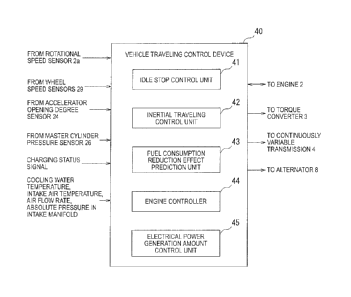
FIG. 2 illustrates the functional configuration of the
vehicle traveling control device 40. The vehicle traveling
control device 40 is provided with an idle stop control unit
41, an inertial traveling control unit 42, a fuel consumption
- 13 -
CA 02997232 2018-03-01
reduction effect prediction unit 43, an engine controller 44,
and an electrical power generation amount control unit 45.
The idle stop control unit 41 performs so-called idle
stop (also called idle reduction) control which stops engine
idling when a predetermined condition is satisfied while the
vehicle 1 is stopped. A detailed description of the idle stop
control is omitted.
[0022]
The inertial traveling control unit 42 stops fuel supply
to engine 2 to stop the engine 2, disconnects the forward
clutch 16, and run the vehicle 1, with the engine 2
disconnected from the drive wheels 6a and 6b when the driver
has no intention for acceleration during vehicle traveling
even if the traveling speed Vv of the vehicle is faster than
the predetermined speed Vl. A representation "inertial
traveling" herein means traveling during which the traveling
speed Vv is faster than the predetermined speed V1, fuel
supply to the engine 2 is kept stopped, and the engine 2 is
kept disengaged from the drive wheels 6a and 6b.
[0023]
During inertial traveling, since the vehicle travels
with the forward clutch 16 disconnected, the rotational
driving force of the drive wheels 6a and 6b cannot be input
to the alternator 8, and therefore, deceleration energy
regeneration cannot be performed. When the cruising
duration of inertial traveling is short, fuel efficiency will
worsen because deceleration energy loss owing to the
- 14 -
CA 02997232 2018-03-01
impossibility of its regeneration exceeds the fuel
consumption reduction effect by inertial traveling.
Therefore, when it is determined that the driver has no
intention for acceleration, the fuel consumption reduction
effect prediction unit 43 predicts whether or not a fuel
consumption reduction effect El by inertial traveling is
superior to a fuel consumption reduction effect E2 by
deceleration energy regeneration in which the rotational
power of the drive wheels 6a and 6b is input to the alternator
8.
[0024]
When it is determined that the fuel consumption reduction
effect El by inertia] traveling is superior to the fuel
consumption reduction effect E2 by deceleration energy
regeneration, the inertial traveling control unit 42 performs
inertial traveling. For example, the inertial traveling
control unit 42 performs inertial traveling when all of the
following conditions (Al) to (A3) are satisfied, and it
prohibits inertial traveling when any one of the conditions
(Al) to (A3) is not satisfied.
(Al) The driver has no intention for acceleration. For
example, the inertial traveling control unit 42 receives the
accelerator pedal operation degree signal from the
accelerator pedal opening degree sensor 24. When a time equal
to or longer than a predetermined time elapses after the
accelerator operation degree (i.e., accelerator depression
degree) drops to zero, it may be determined that the driver
- 15 -
CA 02997232 2018-03-01
has no intention for acceleration. The predetermined time
is a period during which the accelerator pedal 23 is not
operated, the period being set in order to determine that the
driver has no intention for acceleration, and it can be, for
example, 2 seconds.
[0025]
(A2) The fuel consumption reduction effect El by
inertial traveling is expected to be superior to the fuel
consumption reduction effect E2 by deceleration energy
regeneration.
(A3) The driver does not perform braking operation of
the vehicle 1 such as depression of the brake pedal 21.
For example, the inertial traveling control unit 42 may
receive the brake pedal operation degree signal from the
master cylinder pressure sensor 26, to determine that the
braking operation is not performed when the operation degree
of the brake pedal 21 is zero, and that the braking operation
is performed by the driver when the operation degree of the
brake pedal 21 is not zero. Whether or not the braking
operation is performed may also be determined on the basis
of the brake signal from the brake switch 22.
[0026]
When conditions (Al) to (A5), which are the following
conditions (A4) to (A5) added to the conditions (Al) to (A3),
are satisfied, inertial traveling may be performed, and when
any one of the conditions (Al) to (A5) are not satisfied, the
inertial traveling may be prohibited.
- 16 -
CA 02997232 2018-03-01
(A4) The traveling speed Vv is equal to or slower than
a speed V2. For example, the speed V2 may be about 80 km/h.
The inertial traveling control unit 42 may receive the wheel
speed signals from the wheel speed sensors 29 on the basis
of which the unit determines the traveling speed Vv.
(A5) A predetermined idle stop permission condition is
satisfied. The idle stop permission condition may be, for
example, that the engine is not under warming-up, and that
the charging ratio of the battery 9 is equal to or higher than
a predetermined value.
[0027]
On the other hand, when it is determined that the fuel
consumption reduction effect El by inertial traveling is not
higher than the fuel consumption reduction effect E2 by
deceleration energy regeneration, the inertial traveling
control unit 42 performs deceleration energy regeneration.
For example, when all of the conditions (Al), (A3), and the
following condition (B1) are satisfied, the inertial
traveling control unit 42 performs deceleration energy
regeneration, and when any one of the conditions (Al), (A3),
and (B1) is not satisfied, the unit does not perform the
deceleration energy regeneration.
(Al) The driver has no intention for acceleration.
(A3) The driver does not perform braking operation of
the vehicle 1 such as depression of the brake pedal 21.
(B1) The fuel consumption reduction effect El by
inertial traveling is predicted not to be superior to the fuel
- 17 -
CA 02997232 2018-03-01
consumption reduction effect E2 by deceleration energy
regeneration.
[0028]
When inertial traveling is started, the inertial
traveling control unit 42 outputs an inertial traveling start
command to the engine controller 44.
When the engine controller 44 receives the inertial
traveling start command, it stops fuel injection by a fuel
injection device, to stop fuel supply to the engine 2.
Further, the engine controller 44 outputs an operation
prohibition command for the electric oil pump 18 to the
continuously variable transmission 4. Since the oil pump 15
is stopped owing to the stop of the engine 2, and in addition,
the electric oil pump 18 does not operate, the forward clutch
16 in the forward-reverse switching mechanism 11 is released.
As a result, the engine 2 is disengaged from the drive wheels
6a and 6b. In addition, the lock-up clutch 10 is also released.
As a result, the traveling status of vehicle 1 is shifted from
D-range traveling to inertial traveling.
[0029]
When deceleration energy regeneration is started, the
inertial traveling control unit 42 outputs a regeneration
start command to the engine controller 44 and the electrical
power generation amount control unit 45.
Upon receiving the regeneration start command, the
engine controller 44 stops fuel injection by the fuel
injection device, to stop fuel supply to the engine 2.
- 18 -
CA 02997232 2018-03-01
Alternatively, the engine controller 44 reduces fuel
injection amount.
The engine controller 44 activates the electric oil pump
18, to maintain the forward clutch 16 of the forward-reverse
switching mechanism 11. Thus, the engagement of the engine
2 with the drive wheels 6a and 6b is maintained, and the
rotational driving force of the wheels 6a and 6b is input to
the alternator 8.
Further upon receiving the regeneration start command,
the electrical power generation amount control unit 45
outputs, to alternator 8, an electrical power generation
command value signal which raises the target electrical power
generation voltage of the alternator 8. The rotational
driving force of the drive wheels 6a and 6b is input to the
alternator 8, and the target electrical power generation
voltage to be instructed to the alternator 8 is raised, and
thereby, the deceleration energy regeneration is performed
to charge the battery 9.
[0030]
During the inertial traveling, the inertial traveling
control unit 42 determines whether or not a predetermined stop
condition is satisfied. The stop condition is satisfied, for
example, when any one of the following two conditions (Cl)
and (C2) is satisfied.
(Cl) The driver has an intention for acceleration.
(C2) The driver performs braking operation of the
vehicle 1.
- 19 -
CA 02997232 2018-03-01
When the stop condition is satisfied, the inertial
traveling control unit 42 stops inertial traveling. When the
condition (A5) is selected as an inertial traveling start
condition, inertial traveling may be stopped when the
condition (A5) is not satisfied.
When the inertial traveling is stopped, the inertial
traveling control unit 42 outputs an inertial traveling stop
command to the engine controller 44. Upon receiving the
inertial traveling stop command, the engine controller 44
restarts fuel injection and drive the motor 7 to perform
engine cranking. After the engine 2 is restarted, the oil
pump 15 operates to connect the forward clutch 16 in the
forward-reverse switching mechanism 11. Thus, engine
restart and reconnection of the forward clutch 16 are
completed, and the traveling status of the vehicle 1 is
shifted from inertial traveling to D-range traveling.
[0031]
On the other hand, during deceleration energy
regeneration, the inertial traveling control unit 42
determines whether or not the driver has an intention for
acceleration. When the driver has an intention for
acceleration, the inertial traveling control unit 42 stops
the deceleration energy regeneration.
When the inertial traveling control unit 42 stops the
deceleration energy regeneration, it outputs the
regeneration stop command to the engine controller 44 and the
electrical power generation amount control unit 45. Upon
- 20 -
CA 02997232 2018-03-01
receiving the regeneration stop command, the engine
controller 44 restarts fuel injection of the engine 2. The
electrical power generation amount control unit 45 outputs
the electrical power generation command value signal for
lowering the target electrical power generation voltage to
the alternator 8, to reduce electrical power generation by
the alternator 8, and thereby reduces the load on the engine
2. Thus, the deceleration energy regeneration ends.
[0032]
(Operation)
Next, one example of the processing of the vehicle
traveling control device 40 according to the first embodiment
will be explained. See FIG. 3.
In a step 510, the inertial traveling control unit 42
determines whether or not the driver has an intention for
acceleration. When the driver has the intention for
acceleration (step S10: Y), the processing returns to the step
S10. In this case, inertial traveling and deceleration
energy regeneration are not started. When the driver has no
intention for acceleration (step S10: N), processing goes to
a step S11.
In the step S11, the inertial traveling control unit 42
determines whether or not the driver performed braking
operation. When the braking operation was performed (step
S11: Y), the processing returns to the step S10. In this case,
inertial traveling and deceleration energy regeneration are
- 21 -
CA 02997232 2018-03-01
not started. When the braking operation was not performed
(step S11: N), the processing goes to a step S12.
[0033]
In the step S12, the fuel consumption reduction effect
prediction unit 43 determines whether or not the fuel
consumption reduction effect El by inertial traveling is
superior to the fuel consumption reduction effect E2 by
deceleration energy regeneration. When the fuel consumption
reduction effect El is superior to the fuel consumption
reduction effect E2 (step S12: Y), the processing goes to a
step S13.
When the fuel consumption reduction effect El is not
superior to the fuel consumption reduction effect E2 (step
S12: N), the processing goes to a step S14.
In the step S13, the inertial traveling control unit 42
performs inertial traveling. Then the processing ends.
In the step S14, the inertial traveling control unit 42
performs deceleration energy regeneration. Then the
processing ends.
[0034]
(Effect of first embodiment)
The inertial traveling control unit 42 determines a
driver's intention for acceleration during the traveling of
the vehicle 1. When it is determined that the driver has no
intention for acceleration, the fuel consumption reduction
effect prediction unit 43 predicts which is superior between
the fuel consumption reduction effect El by inertial
- 22 -
CA 02997232 2018-03-01
traveling and the fuel consumption reduction effect E2 by the
deceleration energy regeneration, the inertial traveling
making the vehicle 1 travel, with the power transmission
disconnected between the engine 2 and the drive wheels 6a and
6b of the vehicle 1, and the deceleration energy regeneration
inputting the rotational power of the drive wheels ba and 6b
of the vehicle 1 to the alternator 8. When the inertial
traveling control unit 42 determines that the fuel
consumption reduction effect El by inertial traveling is
superior to the fuel consumption reduction effect E2 by
deceleration energy regeneration, it performs inertial
traveling. When the inertial traveling control unit 42
determines that the fuel consumption reduction effect El by
inertial traveling is not superior to the fuel consumption
reduction effect E2 by deceleration energy regeneration, it
performs deceleration energy regeneration.
For this reason, the fuel efficiency deterioration can
be prevented which occurs when the cruising duration of
inertial traveling is short, and therefore, deceleration
energy loss owing to the impossibility of its regeneration
exceeds the fuel consumption reduction effect by the inertial
traveling.
[0035]
(Modified example)
(1) The vehicle traveling control device 40 can also
be applied to vehicles adopting an automatic transmission of
a type other than the continuously variable transmission 4.
- 23 -
CA 02997232 2018-03-01
For example, the vehicle traveljng control device 40 can also
be applied to vehicles adopting an automatic transmission of
a type with a gear pair with parallel axis. Further, the
vehicle traveling control device 40 can be applied not only
to vehicles provided with only an internal combustion engine
as a driving source, but also to hybrid vehicles.
(2) During the inertial traveling, the vehicle
traveling control device 40 may output, to the continuously
variable transmission 4, a release signal for actively
releasing the forward clutch 16, instead of an operation
prohibition command for the electric oil pump 18.
[0036]
(Second embodiment)
Next, the second embodiment will be explained. When the
traveling speed Vv of the vehicle 1 is high, it is considered
that the vehicle 1 is traveling in a stable status and that
inertial traveling will last relatively long after the
inertial traveling starts. Therefore, the fuel consumption
reduction effect El by inertial traveling is considered to
increase with increase in the traveling speed Vv of the
vehicle 1. For this reason, the vehicle traveling control
device 40 according to the second embodiment predicts whether
or not the fuel consumption reduction effect El by inertial
traveling is superior to the fuel consumption reduction
effect E2 by deceleration energy regeneration, on the basis
of the traveling speed Vv of the vehicle 1.
- 24 -
CA 02997232 2018-03-01
The configuration of the vehicle traveling control
device 40 of the second embodiment is the same as that of the
first embodiment described with reference to FIG. 2.
[0037]
The fuel consumption reduction effect prediction unit
43 receives the wheel speed signals from the wheel speed
sensors 29. When it is determined that the driver has no
intention for acceleration, the fuel consumption reduction
effect prediction unit 43 detects the traveling speed Vv of
the vehicle 1 on the basis of the wheel speed signals. The
fuel consumption reduction effect prediction unit 43 predicts
that the fuel consumption reduction effect El by inertial
traveling is superior to the fuel consumption reduction
effect E2 by deceleration energy regeneration when the
traveling speed Vv is equal to or more than a predetermined
speed threshold Vt. The fuel consumption reduction effect
prediction unit 43 predicts that the fuel consumption
reduction effect El by inertial traveling is not superior to
the fuel consumption reduction effect E2 by deceleration
energy regeneration when the traveling speed Vv is less than
the predetermined speed threshold. The predetermined speed
threshold Vt may be, for example, 50 km/h.
[0038]
Next, an example of the processing of the vehicle
traveling control device 40 according to the second
embodiment will be explained. See FIG. 4.
- 25 -
CA 02997232 2018-03-01
The processing from steps S20 to S21 is the some as the
processing from the steps S10 to S11 described with reference
to FIG. 3. When the braking operation is not performed (step
S21: N) , the processing goes to a step S22.
In the step S22, the fuel consumption reduction effect
prediction unit 43 detects a traveling speed Vv upon
determining that the driver has no intention for
acceleration.
[0039]
In a step S23, the fuel consumption reduction effect
prediction unit 43 determines whether or not the traveling
speed Vv is equal to or higher than the speed threshold. When
the traveling speed Vv is equal to or higher than the speed
threshold (step S23: Y) , the processing goes to a step S24.
When the traveling speed Vv is lower than the speed threshold
(step S23: Y) , the processing goes to a step S25.
The processing from the steps S24 to S25 is the same as
the processing from the steps S13 to S14 described with
reference to FIG. 3.
10040]
(Effect of second embodiment)
The fuel consumption reduction effect prediction unit
43 detects the traveling speed Vv of the vehicle 1 upon
determining that the driver has no intention for acceleration.
When the traveling speed Vv is equal to or higher than the
speed threshold Vt, the fuel consumption reduction effect
prediction unit 43 predicts that the fuel consumption
- 26 -
CA 02997232 2018-03-01
reduction effect El by inertial traveling is superior to the
fuel consumption reduction effect E2 by deceleration energy
regeneration. When the traveling speed Vv is lower than the
speed threshold Tt, the fuel consumption reduction effect
prediction unit 43 predicts that the fuel consumption
reduction effect El by inertial traveling is not superior to
the fuel consumption reduction effect E2 by deceleration
energy regeneration.
For this reason, it is possible to predict by a
comparatively simple method whether or not the fuel
consumption reduction effect El by inertial traveling is
superior to the fuel consumption reduction effect E2 by
deceleration energy regeneration, to select appropriate one
from inertial traveling and deceleration energy
regeneration.
[0041]
(Modified example)
(1) When the traveling speed Vv drops to or below the
speed threshold Vt during inertial traveling and the status
of the vehicle 1 is shifted from the inertial traveling to
the deceleration energy regeneration, the driver may feel
uncomfortable owing to the change in the vehicle behavior.
For this reason, after the vehicle 1 at a traveling speed Vv
equal to or more than the speed threshold Vt starts inertial
traveling, the inertial traveling control unit 42 may
continue the inertial traveling when the traveling speed Vv
drops below the speed threshold Vt during this inertial
- 27 -
CA 02997232 2018-03-01
traveling. Thus, the uncomfortable feeling of the driver can
be avoided by preventing the status of the vehicle 1 from being
shifted from inertial traveling to deceleration energy
regeneration.
(2) When the traveling speed Vv increases to the speed
threshold Vt or higher during deceleration energy
regeneration on a downward slope and the status of the vehicle
I is shifted from deceleratei on energy regeneration to
inertial traveling, the driver may feel uncomfortable owing
to the change in the vehicle behavior. For this reason, after
the vehicle 1 at a traveling speed Vv lower than the speed
threshold Vt starts deceleration energy regeneration, the
inertial traveling control unit 42 may continue the
deceleration energy regeneration when the traveling speed Vv
increases to the speed threshold Vt or higher during this
deceleration energy regeneration performed on the downward
slope. Thus, the uncomfortable feeling of the driver can be
avoided by preventing the status of the vehicle 1 from being
shifted from deceleration energy regeneration to inertial
traveling _
[00421
(Third embodiment)
Next, the third embodiment will he explained. When the
driver performs acceleration operation and brake operation,
inertial traveling stops. Further, when the vehicle 1 stops,
the inertial traveling stops. Accordingly, when there is an
object which can be a stopping factor to stop inertial
- 28 -
CA 02997232 2018-03-01
traveling by causing acceleration operation or brake
operation or by stopping the vehicle 1, the cruising duration
of the inertial traveling varies depending on the distance
and relative speed between the object and the vehicle I.
For this reason, the vehicle traveling control device
40 according to the third embodiment detects a distance and
relative speed, upon determining that the driver has no
intention for acceleration, between the vehicle 1 and an
object which can be a stopping factor for inertial traveling.
The vehicle traveling control device 40 predicts whether or
not the fuel consumption reduction effect El by inertial
traveling is superior to the fuel consumption reduction
effect E2 by deceleration energy regeneration, according to
the detected distance and relative speed. In the following
description, the object which may be a stopping factor for
inertial traveling may be simply represented as "object."
[0043]
For example, depending on one of the distance to the
object and the relative speed, the vehicle traveling control
device 40 determines a threshold of the other of the distance
to the object and the relative speed. Then, the vehicle
traveling control device 40 predicts whether or not the fuel
consumption reduction effect El by inertial traveling is
superior to the fuel consumption reduction effect E2 by
deceleration energy regeneration, according to a result of
comparison of the thus determined threshold with the other
of the distance to the object and the relative speed.
- 29 -
CA 02997232 2018-03-01
[0044]
In other words, the vehicle traveling control device 40
determines the threshold of the relative speed with respect
to the object according to the distance to the object; when
the relative speed with respect to the object is less than
the threshold, the device determines that the fuel
consumption reduction effect El by inertial traveling is
superior to the fuel consumption reduction effect E2 by
deceleration energy regeneration; when the relative speed
with respect to the object is equal to or more than the
threshold, the device determines that the fuel consumption
reduction effect El by inertial traveling is not superior to
the fuel consumption reduction effect 2 by deceleration
energy regeneration.
Alternatively, the vehicle traveling control device 40
determines the threshold of the distance to the object
according to the relative speed with respect to the object;
when the distance to the object exceeds the threshold, the
device determines that the fuel consumption reduction effect
El by inertial traveling is superior to the fuel consumption
reduction effect E2 by deceleration energy regeneration; when
the distance to the object is equal to or less than the
threshold, the device determines that the fuel consumption
reduction effect El by inertial traveling is not superior to
the fuel consumption reduction effect E2 by deceleration
energy regeneration.
- 30 -
CA 02997232 2018-03-01
Alternatively, when a ratio which is the distance to the
object divided by the relative speed exceeds a threshold, the
vehicle traveling control device 40 may determine that the
fuel consumption reduction effect El by inertial traveling
is superior to the fuel consumption reduction effect E2 by
deceleration energy regeneration; when the ratio is equal to
or less than the threshold, the device may determine that the
fuel consumption reduction effect El by inertial traveling
is not superior to the fuel consumption reduction effect E2
by deceleration energy regeneration.
[0045]
(Configuration)
The stopping factor for inertial traveling may be, for
example, a factor which causes the braking operation of the
vehicle 1 by the driver. Further, the stopping factor for
inertial traveling may be, for example, a factor which causes
the acceleration operation of the vehicle 1 by the driver.
One example of the object which can be a stopping factor
for inertial traveling is a preceding car traveling ahead of
the vehicle 1. This is because when there is a preceding car,
the vehicle 1 stops inertial traveling owing to the operation
of the brake pedal 21 upon approaching the preceding car and
the subsequent re-acceleration.
One example of the vehicle traveling control device 40
according to the third embodiment predicts whether or not the
fuel consumption reduction effect El by inertial traveling
is superior to the fuel consumption reduction effect E2 by
- 31 -
CA 02997232 2018-03-01
deceleration energy regeneration, according to an
inter-vehicle distance Dv and a relative speed Vr with respect
to a preceding car traveling ahead of the vehicle 1.
See FIG. 5. The same reference signs are used for the
same components as those in the first embodiment described
with reference to FIG. 1. The vehicle 1 is provided with a
distance measurement unit 50 for measuring the inter-vehicle
distance Dv between the vehicle 1 and a preceding car and a
relative speed measurement unit 51 for measuring the relative
speed Vr Hereinafter, the inter-vehicle distance Dv and the
relative speed Vr with respect to the preceding car may be
represented as "inter-vehicle distance Dv" and "relative
speed Vr", respectively.
The distance measurement unit 50 and the relative speed
measurement unit 51 may be, for example, radar devices such
as laser radars and millimeter wave radars for scanning a
region ahead of the vehicle. The distance measurement unit
50 may be an imaging device for imaging a region ahead of the
vehicle and an information processing device for calculating
the inter-vehicle distance Dv on the basis of the image of
the region. The relative speed measurement unit 51 may be
an information processing device for calculating temporal
change, as the relative speed Vr, in the inter-vehicle
distance Dv calculated on the basis of the image of the forward
region.
[0046]
- 32 -
CA 02997232 2018-03-01
FIG. 6 illustrates the functional configuration of the
vehicle traveling control device 40 of the third embodiment.
The same reference signs are used for the same components as
those in the first embodiment described with reference to FIG.
2. The vehicle traveling control device 40 is provided with
a threshold determination unit 46 for determining, according
to the inter-vehicle distance Dv, a relative speed threshold
Vrt which is a threshold of the relative speed Vr.
The threshold determination unit 46 determines, for
example, on the basis of a map illustrated in FIG. 7, the
relative speed threshold Vrt according to the inter-vehicle
distance Dv between a preceding car and the vehicle 1 upon
determining that the driver has no intention for acceleration.
This map can be determined in advance by, for example, an
experiment and stored in a storage device provided in the
engine control unit 20.
[0047]
In this map, a distance D1 is preset which satisfies 0
< D1 for the inter-vehicle distance Dv. The distance D1 is
set such that, when the inter-vehicle distance Dv is less than
or equal to D1, the fuel consumption reduction effect El is
not superior to the fuel consumption reduction effect E2 by
deceleration energy regeneration, regardless of the relative
speed Vr. When the inter-vehicle distance Dv is in a range
fiom 0 to D1 inclusive, the relative speed threshold Vrt is
0 regardless of the inter-vehicle distance Dv. When the
inter-vehicle distance Dv is in a range larger than D1, the
- 33 -
CA 02997232 2018-03-01
relative speed threshold Vrt is larger for a longer
inter-vehicle distance Dv.
[0048]
Instead of using the map illustrated in FIG. 7, the
threshold determination unit 46 may use a predetermined
formula for calculating the relative speed threshold Vrt
according to the inter-vehicle distance Dv, on the basis of
which formula the relative speed threshold Vrt is to be
determined.
When the relative speed Vr upon determining that the
driver has no intention for acceleration is less than the
relative speed threshold Vrt, the fuel consumption reduction
effect prediction unit 43 predicts that the fuel consumption
reduction effect El by inertial traveling is superior to the
fuel consumption reduction effect E2 by deceleration energy
regeneration. When the relative speed Vr is equal to or
higher than the relative speed threshold Vrt, the fuel
consumption reduction effect prediction unit 43 predicts that
the fuel consumption reduction effect El by inertial
traveling is not superior to the fuel consumption reduction
effect E2 by deceleration energy regeneration.
(Operation)
Next, an example of the processing of the vehicle
traveling control device 40 according to the third embodiment
will be explained. See FIG. 8.
The processing from the steps S30 to S31 is the same as
the processing from the steps S10 to Sll described with
- 34 -
CA 02997232 2018-03-01
reference to FIG. 3. When the braking operation is not
performed (step S31: N) the processing goes to a step S22.
In a step S32, the distance measurement unit 50 detects
the inter-vehicle distance Dv when it is determined that the
driver has no intention for acceleration.
[0049]
In a step S33, the threshold determination unit 46
determines the relative speed threshold Vrt according to the
inter-vehicle distance Dv. In a step S34, the relative speed
measurement unit 51 detects the relative speed Vr when it is
determined that the driver has no intention for acceleration.
The processing in the step S33 may be performed after the
processing in the step S34.
In the step S35, the fuel consumption reduction effect
prediction unit 43 determines whether or not the relative
speed Vr is lower than the relative speed threshold Vrt. When
the relative speed Vr is lower than the relative speed
threshold Vrt (step S35: Y) , the processing goes to a step
S36. When the relative speed Vr is equal to or higher than
the relative speed threshold Vrt (step S35: N) , the processing
goes to a step S37.
The processing from the steps S36 to 537 is the same as
the processing from the steps S13 to S14 described with
reference to FIG. 3.
[0050]
(Effect of third embodiment)
- 35 -
CA 02997232 2018-03-01
(1) The distance measurement unit 50 and the relative
speed measurement unit 51 detect the distance and the relative
speed between the vehicle 1 and an object which can be a
stopping factor for inertial traveling, upon determining that
the driver has no intention for acceleration. The fuel
consumption reduction effect prediction unit 43 predicts
whether or not the fuel consumption reduction effect El by
inertial traveling is superior to the fuel consumption
reduction effect E2 by deceleration energy regeneration,
according to the detected distance and the relative speed.
For this reason, when there is a stopping factor for
inertial traveling, it is possible to predict whether or not
the fuel consumption reduction effect El by inertial
traveling is superior to the fuel consumption reduction
effect E2 by deceleration energy regeneration, and select
appropriate one from inertial traveling and deceleration
energy regeneration.
[0051]
(2) According to one of the distance and the relative
speed between the vehicle 1 and the object which can be a
stopping factor for inertial traveling, upon determining that
the driver has no intention for acceleration, the threshold
determination unit 46 determines the threshold of the other
of the distance and the relative speed. The fuel consumption
reduction effect prediction unit 43 predicts whether or not
the fuel consumption reduction effect El by inertial
traveling is superior to the fuel consumption reduction
- 36 -
CA 02997232 2018-03-01
effect E2 by deceleration energy regeneration, according to
a result of comparison of the determined threshold with the
other of the distance and the relative speed.
For this reason, on the basis of the distance and the
relative speed between the vehicle land the object which can
be a stopping factor for inertial traveling, it is possible
to predict whether or not the fuel consumption reduction
effect El by inertial traveling is superior to the fuel
consumption reduction effect E2 by deceleration energy
regeneration, and select appropriate one from inertial
traveling and deceleration energy regeneration.
[0052]
(3) When there is a preceding car traveling ahead of
the vehicle 1as an object which can be a stopping factor for
inertial traveling, the fuel consumption reduction effect
prediction unit 43 predicts whether or not the fuel
consumption reduction effect El by inertial traveling is
superior to the fuel consumption reduction effect E2 by
deceleration energy regeneration, according to the
inter-vehicle distance Dv and the relative speed Vr between
the preceding car and the vehicle 1.
For this reason, when there is a preceding car traveling
ahead of the vehicle 1, it is possible to predict whether or
not the fuel consumption reduction effect El by inertial
traveling is superior to the fuel consumption reduction
effecf E2 by deceleration energy regeneration, and select
- 37 -
CA 02997232 2018-03-01
appropriate one from inertial traveling and deceleration
energy regeneration.
[0053]
(Modified example)
The threshold determination unit 46 may determine a
threshold D of the inter-vehicle di stance Dv according to the
relative speed Vr. When the inter-vehicle distance Dv is
longer than the threshold D, the fuel consumption reduction
effect prediction unit 43 may predict that the fuel
consumption reduction effect El for inertial traveling is
superior to the fuel consumption reduction effect E2 by
deceleration energy regeneration. When the inter-vehicle
distance Dv is less than the threshold D, the fuel consumption
reduction effect prediction unit 43 may predict that the fuel
consumption reduction effect El for inertial traveling is not
superior to the fuel consumption reduction effect E2 by
deceleration energy regeneration.
[0054]
(Fourth embodiment)
Next, the fourth embodiment will be explained. The
stopping factor for inertial traveling may be, for example,
a factor which stops the vehicle 1. One example of the object
which can be a stopping factor for inertial traveling owing
to stopping the vehicle 1 is a red traffic light.
The vehicle traveling control device 40 according to the
fourth embodiment predicts whether or not the fuel
consumption reduction effect El by inertial traveling is
- 38 -
CA 02997232 2018-03-01
superior to the fuel consumption reduction effect E2 by
deceleration energy regeneration, according to the distance
Dr between the vehicle 1 and a red traffic light on the route
of the vehicle 1 and the traveling speed Vv of the vehicle
1 which is a relative speed between the red traffic light and
the vehicle 1.
[0055]
(Configuration)
See FIG. 9. The same reference signs are used for the
same components as those in the first embodiment described
with reference to FIG. 1. The vehicle 1 is provided with a
traffic light detection unit 52 for detecting the distance
Dr to a red traffic light forward on the route of the vehicle
1.
The traffic light detection unit 52 is configured, for
example, by a positioning device such as a global positioning
system (GPS) device or an inertial navigation device for
measuring the present position of the vehicle 1, an
information processing device such as a navigation device for
storing position information of traffic lights on roads, and
a receiver for receiving the lighting status of traffic lights
on roads via road-to-vehicle communication or inter-vehicle
communication.
Further, the traffic light detection unit 52 may be an
imaging device for imaging a region ahead of the vehicle and
an information processing device for calculating the distance
- 39 -
CA 02997232 2018-03-01
Dr to a red traffic light forward on the route of the vehicle
1, on the basis of the image of the region.
[0056]
FIG. 10 illustrates the functional configuration of a
vehicle traveling control device 40 according to the fourth
embodiment. The same reference signs are used for the same
components as those in the first embodiment described with
reference to FIG. 2.
When the traveling speed Vv of the vehicle 1 is lower
than a fixed first speed threshold Vtl, the fuel consumption
reduction effect prediction unit 43 predicts that the fuel
consumption reduction effect El by inertial traveling is not
superior to the fuel consumption reduction effect E2 by
deceleration energy regeneration, regardless of the distance
75 Dr to the red traffic light. As a result, when the traveling
speed Vv is less than the first speed threshold Vt1, the
inertial traveling control unit 42 performs deceleration
energy regeneration regardless of the distance Dr.
[0057]
The vehicle traveling control device 40 is provided with
a threshold determination unit 46 for determining, according
to distance Dr to the red traffic light, a variable second
speed threshold Vt2 which is a threshold of the traveling
speed Vv_
The threshold determination unit 46 determines, for
example, on the basis of a map illustrated in FIG. 11, the
second speed threshold Vt2 according to the distance Dr from
- 40 -
CA 02997232 2018-03-01
the vehicle 1 to the red traffic light upon determining that
the driver has no intention for acceleration. This map can
be determined in advance by, for example, an experiment and
stored in a storage device provided in the engine control unit
20.
[0058]
In this map, a distance D2 is preset which satisfies 0
< D2 for the distance Dr to the red traffic light. The
distance D2 is set such that, when the distance Dr is equal
to or less than D2, the fuel consumption reduction effect El
is not superior to the fuel consumption reduction effect E2
by deceleration energy regeneration, regardless of the
traveling speed Vv. When the distance Dr is in a range from
0 to D2 inclusive, the second speed threshold Vt2 is 0
regardless of the distance Dr. When the distance Dr is in
the range larger than D2, the second speed threshold Vt2
increases from the first speed threshold Vtl with increase
in the distance Dr.
[0059]
Instead of using the map illustrated in FIG. 11, the
threshold determination unit 46 may use a predetermined
formula for calculating the second speed threshold Vt2
according to the distance Dr to the red traffic light, on the
basis of which formula the second speed threshold Vt2 is to
be determined.
When the traveling speed Vv is lower than the second speed
threshold Vt2, the fuel consumption reduction effect
- 41 -
CA 02997232 2018-03-01
prediction unit 43 predicts that the fuel consumption
reduction effect El by inertial traveling is superior to the
fuel consumption reduction effect E2 by deceleration energy
regeneration. When the traveling speed Vv is equal to or
higher than the second speed threshold Vt2, the fuel
consumption reduction effect predi ction unit 43 predicts that
the fuel consumption reduction effect El by inertial
traveling is not superior to the fuel consumption reduction
effect E2 by deceleration energy regeneration.
[0060]
(Operation)
Next, an example of the processing of the vehicle
traveling control device 40 according to the fourth
embodiment will be explained. See FIG. 12.
The processing from steps S40 to S41 is the same as the
processing from the steps S10 to S11 described with reference
to E1C-. 3. When braking operation is not performed (step S41:
N) , the processing goes to a step S42.
In the step 542, the traffic light detection unit 52
detects the distance Dr to a red traffic light from the vehicle
1 upon determining that the driver has no intention for
acceleration. In the step S43, the fuel consumption
reduction effect prediction unit 43 determines whether or not
there is a red traffic light within the predetermined distance.
When there is a red traffic light within the predetermined
distance (step 543: Y) , the processing goes to a step S44.
- 42 -
CA 02997232 2018-03-01
When there is no red traffic light within the predetermined
distance (step S43: N) , the fuel consumption reduction effect
prediction unit 43 determines that the fuel consumption
reduction effect El by inertial traveling is superior to the
fuel consumption reduction effect E2 by deceleration energy
regeneration, and proceeds the processing to a step 542.
[0061]
In the step S44, the fuel consumption reduction effect
prediction unit 43 detects the traveling speed Vv upon
determining that the driver has no intention for acceleration.
In a step S45, the fuel consumption reduction effect
prediction unit 13 determines whether or not the traveling
speed Vv is less than the first speed threshold Vtl. When
the traveling speed Vv is lower than the first speed threshold
Vtl (step S45: Y), the fuel consumption reduction effect
prediction unit 43 determines that the fuel consumption
reduction effect El by inertial traveling is not superior to
the fuel consumption reduction effect E2 by deceleration
energy regeneration, and proceeds the processing to a step
S49. When the traveling speed Vv is equal to or more than
the first speed threshold Vtl (step S45: N), the processing
goes to a step S46.
In the step S46, the threshold determination unit 46
determines the second speed threshold Vt2 according to the
distance Dr to the red traffic light.
10062]
- 43 -
CA 02997232 2018-03-01
In the step S47, the fuel consumption reduction effect
prediction unit 43 determines whether or not the traveling
speed Vv is less than the second speed threshold Vt2. When
the traveling speed Vv is less than the second speed threshold
Vt2 (step S47: Y) , the processing goes to a step S48.
When the traveling speed Vv is equal to or more than the second
speed threshold Vt2 (step S47: N) , the processing goes to a
step S49.
The processing from the steps S48 to S49 is the same as
the processing from the steps S13 to S14 described with
reference to FIG. 3.
[0063]
(Effect of fourth embodiment)
(1) When there is a red traffic light as an object, which
can be a stopping factor for inertial traveling, on the route
of the vehicle 1, the fuel consumption reduction effect
prediction unit 43 predicts whether or not the fuel
consumption reduction effect El by inertial traveling is
superior to the fuel consumption reduction effect E2 by
deceleration energy regeneration, according to the distance
Dr between the vehicle 1 and the red traffic light and the
traveling speed Vv of the vehicle 1, which is a relative speed
between the red traffic light and the vehicle 1.
For this reason, when there is a red traffic light on
the route of the vehicle 1, it is possible to predict whether
or not the fuel consumption reduction effect El by inertial
traveling is superior to the fuel consumption reduction
- 44 -
CA 02997232 2018-03-01
effect E2 by deceleration energy regeneration, and select
appropriate one from inertial traveling and deceleration
energy regeneration.
[0064]
(Modified example)
The threshold determination unit 46 may determine the
threshold D of the distance Dr to the red traffic light
according to the traveling speed Vv. When the distance Dr
is longer than the threshold D, the fuel consumption reduction
effect prediction unit 43 may predict that the fuel
consumption reduction effect El for inertial traveling is
superior to the fuel consumption reduction effect E2 by
deceleration energy regeneration. When the distance Dr is
equal to or less than the threshold D, the fuel consumption
reduction effect prediction unit 43 may predict that the fuel
consumption reduction effect El for inertial traveling is not
superior to the fuel consumption reduction effect E2 by
deceleration energy regeneration.
[0065]
(Fifth embodiment)
Next, the fifth embodiment will be explained. When the
vehicle 1 turns to right or left at an intersection, the
inertial traveling is stopped upon performing braking
operation of the vehicle 1 by the driver. Alternatively, the
inertial traveling is stopped owing to the re-acceleration
of the vehicle 1 after the right turn or left turn is completed.
- 45 -
CA 02997232 2018-03-01
Accordingly, when a scheduled route of the vehicle 1 is
set in advance by the navigation device, an intersection where
the vehicle 1 will next turn to right or left on the scheduled
route of the vehicle 1 can be detected as a stopping factor
for inertial traveling.
The vehicle traveling control device 40 according to the
fifth embodiment predicts whether or not the fuel consumption
reduction effect E1 by inertial traveling is superior to the
fuel consumption reduction effect E2 by deceleration energy
regeneration, according to the distance Dt between the
vehicle 1 and an intersection where the vehicle 1 will next
turn to right or left on the scheduled route of the vehicle
1 and the traveling speed Vv of the vehicle 1 which is a
relative speed between the intersection and the vehicle 1.
[0066]
(Configuration)
See FIG. 13. The same reference signs are used for the
same components as those in the first embodiment described
with reference to FIG. 1. The vehicle 1 is provided with an
intersection detection unit 53 for detecting the distance Dt
between the vehicle 1 and an intersection where the vehicle
1 will next turn to right or left on the scheduled route of
the vehicle 1.
The intersection detection unit 53 is, for example,
configured by a positioning device, such as a GPS (Global
Positioning System) device or an inertial navigation device,
for measuring the present position of the vehicle 1, and an
- 46 -
CA 02997232 2018-03-01
information processing device, such as a navigation device,
which includes a map database including information on the
position of a intersection and performs route search and route
guide for the vehicle 1. The intersection detection unit 53
detects the position of a intersection where the vehicle I
will next turn to right or left on the scheduled route of the
vehicle 1 set according to route search, and calculates the
distance Dt between the intersection and the vehicle 1, on
the basis of the position of the intersection and the present
position of the vehicle 1.
[0067]
FIG. 14 illustrates the functional configuration of the
vehicle traveling control device 40 of the fifth embodiment.
The same reference signs are used for the same components as
those in the first embodiment described with reference to FIG.
2.
When the traveling speed Vv of the vehicle 1 is lower
than a fixed third speed threshold Vt3, the fuel consumption
reduction effect prediction unit 43 predicts that the fuel
consumption reduction effect El by inertial traveling is not
superior to the fuel consumption reduction effect E2 by
deceleration energy regeneration, regardless of the distance
Dt to an intersection where to turn to right or left next.
As a result, when the traveling speed Vv is less than the third
speed threshold Vt3, the inertial traveling control unit 42
performs deceleration energy regeneration regardless of the
distance Dt.
- 47 -
CA 02997232 2018-03-01
[0068]
The vehicle traveling control device 40 is provided with
the threshold determination unit 46 for determining a
variable second speed threshold Vt2, which is a threshold of
the traveling speed Vv, according to the distance Dt to an
intersection where to turn to right or left next.
The threshold determination unit 46 determines, for
example, on the basis of a map illustrated in FIG. 15, the
second speed threshold Vt2 according to the distance Dt from
the vehicle 1 to the intersection where to turn to right or
left next, upon determining that the driver has no intention
for acceleration. This map can be determined in advance, for
example, by an experiment and stored in a storage device
provided in the engine control unit 20.
[0069]
In this map, a distance D3 is preset which satisfies 0
< D3 for the distance Dt to the intersection where to turn
to right or left next. The distance D3 is set such that, when
the distance Dt is equal to or less than D3, the fuel
consumption reduction effect Fl is not superior to the fuel
consumption reduction effect E2 by deceleration energy
regeneration, regardless of the traveling speed Vv. When the
distance Dt is in a range from 0 to D3 inclusive, the second
speed threshold Vt2 is 0 regardless of the distance De. When
the distance Dt is in a range larger than D3, the second speed
threshold Vt2 increases from the third speed threshold Vt3
with increase in the distance Dt.
- 48 -
CA 02997232 2018-03-01
[ 0 0 7 0
Instead of using the map illustrated in FIG. 15, a
predetermined formula for calculating the second speed
threshold Vt2 may be used, on the basis of which formula the
second speed threshold Vt2 is to be determined according to
the distance Dt to the intersection where to turn to right
or left next.
When the traveling speed Vv is lower than the second speed
threshold Vt2, the fuel consumption reduction effect
prediction unit 43 predicts that the fuel consumption
reduction effect El by inertial traveling is superior to the
fuel consumption reduction effect E2 by deceleration energy
regeneration. When the traveling speed Vv is equal to or
higher than the second speed threshold Vt2, the fuel
consumption reduction ef fect prediction unit 93 predicts that
the fuel consumption reduction effect El by inertial
traveling is not superior to the fuel consumption reduction
effect E2 by deceleration energy regeneration.
[0071]
(Operation)
Next, an example of the processing of the vehicle
traveling control device 40 according to the fifth embodiment
will be explained. See FIG. 16.
The processing from steps S50 to S51 is the same as the
processing from the steps S10 to Sll described with reference
to FIG. 3. When the braking operation is not performed (step
S51: N), the processing goes to a step S52.
- 49 -
CA 02997232 2018-03-01
In the step S52, the traffic light detection unit 52
detects the distance Dt from the vehicle 1 to an intersection
where to turn to right or left next, upon determining that
the driver has no intention for acceleration. In a step S53,
the fuel consumption reduction effect prediction unit 43
determines whether or not there is an intersection where to
turn to right or left next within the predetermined distance.
When there is an intersection within the predetermined
distance (step S53: Y) , the processing goes to a step S54.
When there is no intersection within the predetermined
distance (step S53: N) , the fuel consumption reduction effect
prediction unit 43 determines that the fuel consumption
reduction effect El by inertial traveling is superior to the
fuel consumption reduction effect E2 by deceleration energy
regeneration, and proceeds the processing to a step S58.
[0072]
In the step S54, the fuel consumption reduction effect
prediction unit 43 detects a traveling speed Vv upon
determining that the driver has no intention for acceleration.
In a step 555, the fuel consumption reduction effect
prediction unit 43 determines whether or not the traveling
speed Vv is less than the third speed threshold Vt3. When
the traveling speed vv is lower than the third speed threshold
Vt3 (step S55: Y) , the fuel consumption reduction effect
prediction unit 43 determines that the fuel consumption
reduction effect El by inertial traveling is not superior to
the fuel consumption reduction effect E2 by deceleration
- 50 -
CA 02997232 2018-03-01
energy regeneration, and proceeds the processing to a step
S59. When the traveling speed Vv is equal to or more than
the third speed threshold Vt3 (step S55: N), the processing
goes to a step S56.
In the step S56, the threshold determination unit 46
determines the second speed threshold Vt2 according to the
distance Dt to an intersection where to turn to right or left
next.
The processing from steps S57 to S59 is the same as the
processing from the steps from S47 to S49 described with
reference to FIG. 12.
[0073]
(Effect of fifth embodiment)
(1) An intersection where the vehicle 1 will next turn
to right or left on a scheduled route of the vehicle 1 is
detected as an object which can be a stopping factor for
inertial traveling. The fuel consumption reduction effect
prediction unit 43 predicts whether or not the fuel
consumption reduction effect El by inertial traveling is
superior to the fuel consumption reduction effect E2 by
deceleration energy regeneration, according to the distance
Dt between the vehicle 1 and the intersection where to turn
to right or left next and a traveling speed SA7 of the vehicle
1 which is a relative speed between the intersection and the
vehicle 1.
For this reason, when the intersection where the vehicle
1 will next turn to right or left is already determined, it
- 51 -
CA 02997232 2018-03-01
is possible to predict whether or not the fuel consumption
reduction effect El by inertial traveling is superior to the
fuel consumption reduction effect E2 by deceleration energy
regeneration, and select appropriate one from inertial
traveling and deceleration energy regeneration.
[0074]
(Modified example)
The threshold determination unit 46 may determine the
threshold D of the distance Dt between the vehicle 1 and an
intersection where the vehicle 1 will next turn to right or
left, according to the traveling speed Vv. When the distance
Dt is longer than the threshold D, the fuel consumption
reduction effect prediction unit 43 may predict that the fuel
consumption reduction effect El by inertial traveling is
superior to the fuel consumption reduction effect E2 by
deceleration energy regeneration. When the distance Dt is
equal to or shorter than the threshold D, the fuel consumption
reduction effect prediction unit 43 may predict that the fuel
consumption reduction effect El by inertial traveling is not
superior to the fuel consumption reduction effect E2 by
deceleration energy regeneration.
[0075]
The description is made herein while referring to the
limited number of embodiments. However, the scope of rights
is not limited to these, and for those skilled in the art,
modifications of the respective embodiments, which are based
on the above-described disclosure, are obvious.
- 52 -
CA 02997232 2018-03-01
Reference Signs List
[0076]
1 ... vehicle, 2 ... engine, 2a ... rotational speed
sensor, 3 ... torque converter , 4 ... continuously variable
transmission, 5 ... differential gear, 6a to 6b ... drive
wheel, 7 ... motor, 8 ... alternator, 9 ... battery, 10 ...
lock-up clutch, 11 ... forward and backward switching
mechanism, 12 ... primary pulley, 13 ... secondary pulley,
14 belt, 15 ... oil pump, 16 ... forward clutch, 17 ...
reverse brake, 18 ... electric oil pump, 19 ... rotational
speed sensor, 20 ... engine control unit, 21 ... brake pedal,
22 ... brake switch, 23 ... accelerator peda], 24 ...
accelerator pedal opening degree sensor, 25 ... master
cylinder, 26 ... master cylinder pressure sensor, 27 ...
master back, 29a to 29b ... wheel speed sensor, 30 ...
transmission control unit, 40 ... vehicle traveling control
device, 41 ... idle stop control unit, 42 ... inertial
traveling control unit, 43 ... fuel consumption reduction
effect prediction unit, 44 engine controller,
45 ...
electrical power generation amount control unit, 46 ...
threshold determination unit, 50 ... distance measurement
unit, 51 ... relative speed measurement unit, 52 ... traffic
light detection unit, 53 ... intersection detection unit
- 53 -