Note: Descriptions are shown in the official language in which they were submitted.
CA 02997277 2018-03-01
1
wo 2017/044045
PCT/SG2016/050437
DEVICE FOR DIRECT TO GARMENT PRINTING
FIELD OF INVENTION
This invention relates to a platen for direct to clothing (DTC) or direct to
garment (DTG)
printing, an apparatus containing said platen and associated methods.
BACKGROUND
The listing or discussion of a prior-published document in this specification
should not
necessarily be taken as an acknowledgement that the document is part of the
state of the art
or is common general knowledge.
The apparel industry has recently entered the age of "Fast Fashion", where
turn-around
times are key to market success. Being able to respond quickly to fickle
consumer trends
will provide a decisive competitive advantage in the apparel sector to both
manufacturers
and retailers. The use of ink-jet printing technology to accelerate garment
sample
development and facilitate faster and more cost-effective small-scale
production runs shows
great promise. This type of printing is known as direct to garment (or DTG)
printing. In
addition, the use of DTG printing to print onto premade garments may result in
significant
time- and cost-savings over current production and logistical methods. This is
because DTG
printing can be applied on a garment at, or very close to, the point of sale.
However, current DTG printers are limited to providing and image, pattern or
block of colour
onto a single surface of a garment, such as a T-shirt. As such, current DTG
printers are
used to embellish part of one surface of a garment and cannot currently be
effectively used
to provide a pattern or colour across an entire garment's outer surface. This
is because any
attempt to use a current commercially available printer will result in a
noticeable seam and,
potentially, a misalignment of the pattern to be printed across the entire
surface of the
garment. This is aesthetically unpleasing and results in reduced consumer
satisfaction with
the resulting garment.
There remains a need to provide improved DTG printers that can deliver
seamless and,
potentially, fully-aligned patterns across the surface of a garment. Such
printers would
enable manufacturers and retailers to respond very quickly to changing fashion
trends and
demand on a more local level, potentially resulting in greater profit and less
wastage of
materials.
CA 02997277 2018-03-01
2
wo 2017/044045
PCT/SG2016/050437
SUMMARY OF INVENTION
The current invention provides a direct to clothing (DTC) platen that enables
wrap-around
printing of an item of clothing to be achieved. A DTC printing system that
makes use of said
platen is also provided. An item of clothing having a wrap-around print is
also provided.
Aspects and embodiments of the invention will now be discussed below.
In a first aspect of the invention, there is provided a platen for printing on
an item of clothing,
wherein the platen comprises:
a first planar surface;
a second planar surface, the second planar surface opposite to the first
planar
surface and separated from the first planar surface in an axial direction; and
at least one peripheral region extending from the first planar surface to the
second planar
surface,
wherein the platen further comprises a tapered region comprising a tapered
edge
formed on at least part of the at least one peripheral region.
In a second aspect of the invention, there is provided a platen for printing
an item of clothing.
The platen comprises a plurality of elongate segments, each segment comprising
a tapered
region comprising a tapered edge, the tapered edges being configured to hold
an item of
clothing in a taut arrangement for printing.
In embodiments of the first and second aspects of the invention:
(a) the tapered edge may a double-sided tapered edge;
(b) a minimum thickness of the tapered edge formed on the tapered region
may
be from 0.5 mm to 150 mm (e.g. from 0.5 mm to 50 mm, from 0.7 to 5 mm, or
from 1 to 3 mm, such as 2 mm);
(c) for embodiments of the first aspect of the invention, a maximum
separation of
the first and second planar surfaces may be from 0.5 mm to 50 mm (e.g. from
0.7 mm to 5 mm, or from 1 to 3 mm, such as 2 mm);
(d) the at least one tapered region may have a width of from 2 mm to 100 mm
(e.g. from 2.5 to 10 mm, or from 3 mm to 5 mm, such as 4 mm);
(e) the at least one tapered region may have a taper angle of from 0.1 to
89.5
(e.g. from 45 to 85 , such as from 70 to 80 , such as 78 )
(f) for embodiments of the first aspect of the invention, the first and
second
planar surfaces may further comprise an absorbent material.
CA 02997277 2018-03-01
3
wo 2017/044045
PCT/SG2016/050437
In a third aspect of the invention, there is provided a platen for printing on
an item of clothing,
wherein the platen comprises:
a first planar surface;
a second planar surface, the second planar surface opposite to the first
planar
surface and separated from the first planar surface in an axial direction; and
at least one peripheral region extending from the first planar surface to the
second planar
surface, wherein
the platen further comprises a means or apparatus to transfer part of an item
of
clothing disposed on the first surface of the platen onto the second surface
of the platen.
In one embodiment of this aspect, the means or apparatus to transfer part of
an item of
clothing disposed on the first surface of the platen onto the second surface
of the platen may
be at least one edge flipping mechanism attached to the at least one
peripheral region. In
an alternate embodiment of this aspect, the means or apparatus to transfer
part of an item of
clothing disposed on the first surface of the platen onto the second surface
of the platen may
be at least one toothed rotary actuator mechanism attached to the peripheral
region of the
platen.
In embodiments of the third aspect of the invention:
(a) the peripheral edge may further comprise one or more extendible
sections for
stretching an item of clothing (e.g. using springs or pneumatics and/or where
the extendible sections may be manually controlled, automated or self-
adjusting (e.g. by spring-tension));
(b) the
platen may be made from one or more materials selected from the group
consisting of a metal (e.g. aluminium, stainless steel), a fiber glass and a
composite material (e.g. a carbon composite material);
(c) the platen may be a direct to clothing platen.
In a fourth aspect of the invention, there is provided a printing system
comprising a platen as
described in the first, second, or third aspects of the invention and
technically sensible
combinations of embodiments thereof, a template for alignment of the platen,
and a printer.
In embodiments of the system:
(a) the
system may further comprise a means or apparatus to automatically
rotate the platen from a first position having a first surface exposed to the
printer to a second
position having a second surface exposed to the printer;
CA 02997277 2018-03-01
4
WO 2017/044045
PCT/SG2016/050437
(b) the system may further comprise an integral means or apparatus
for curing an
ink and/or an item of clothing after printing, optionally wherein the means or
apparatus for
curing is an apparatus to generate hot air or an infra-red lamp;
(c) the system may be a direct to clothing system;
(d) the platen may be a direct to clothing platen.
In a fifth aspect of the invention, there is provided a method of printing on
an item of clothing,
comprising placing an item of clothing on a platen as described in the first
to third aspects of
the invention and any technically sensible combination of embodiments thereof,
printing on a
first section of the item of clothing corresponding to the first planar
surface of the platen, and
printing on a second section of the item of clothing corresponding to the
second planar
surface of the platen.
In a sixth aspect of the invention there is provided an item of clothing
comprising an external
surface comprising at least one wrap-around printed pattern, wherein the
pattern does not
exhibit a seam caused by printing. In certain embodiments, of the invention
the item of
clothing is obtained or obtainable by a direct to clothing printing process.
FIGURES
Figure la depicts a plan view of a platen according to a first embodiment of
the current
invention.
Figure lb depicts a cross section of a tapered edge of a platen according to
the first
embodiment of the current invention along line a-a.
Figure 2a shows an example of a platen for printing on tank tops and/or vests.
Figure 2b shows an example of platen formed from a plurality of parts for
printing on T-shirts.
Figures 3a and 3b depict plan views of platens according to embodiments of the
current
invention.
Figure 4 depicts a cross-sectional view of a platen according to an embodiment
of the
current invention.
Figure 5 depicts a cross-sectional view of a platen according to an embodiment
of the
current invention.
Figures 6a to 6d depict a system according to the current invention.
CA 02997277 2018-03-01
WO 2017/044045
PCT/SG2016/050437
DESCRIPTION
Example embodiments of the invention will now be described more fully
hereinafter with
reference to the accompanying drawings; however, the invention may be embodied
in
5 different forms and should not be construed as limited to the embodiments
set forth herein.
Rather, these embodiments are provided so that this disclosure will be
thorough and
complete, and will fully convey example implementations to those skilled in
the art.
In the drawing figures, the dimensions of layers and regions may be
exaggerated for clarity
of illustration. Like reference numerals refer to like elements throughout.
As the invention allows for various changes and numerous embodiments,
particular
embodiments will be illustrated in the drawings and described in detail in the
written
description. However, this is not intended to limit the present invention to
particular modes of
practice, and it will to be appreciated that all changes, equivalents, and
substitutes that do
not depart from the technical scope are encompassed in the present invention.
In the
description, certain detailed explanations of related art are omitted when it
is deemed that
they may unnecessarily obscure the essence of the invention. While such terms
as "first,"
"second," etc., may be used to describe various components, such components
must not be
limited to the above terms. The above terms are used only to distinguish one
component
from another. The terms used in the present specification are merely used to
describe
particular embodiments, and are not intended to limit the present invention.
An expression
used in the singular encompasses the expression of the plural, unless it has a
clearly
different meaning in the context. In the present specification, it is to be
understood that the
terms such as "including" or "having," etc., are intended to indicate the
existence of the
features, numbers, steps, actions, components, parts, or combinations thereof
disclosed in
the specification, and are not intended to preclude the possibility that one
or more other
features, numbers, steps, actions, components, parts, or combinations thereof
may exist or
may be added. Also, expressions such as "at least one of," when preceding a
list of
elements, modify the entire list of elements and do not modify the individual
elements of the
list.
In embodiments herein, the word "comprising" may be interpreted as requiring
the features
mentioned, but not limiting the presence of other features. Alternatively, the
word
"comprising" may also relate to the situation where only the
components/features listed are
intended to be present (e.g. the word "comprising" may be replaced by the
phrases "consists
of" or "consists essentially of'). It is explicitly contemplated that both the
broader and
CA 02997277 2018-03-01
6
WO 2017/044045
PCT/SG2016/050437
narrower interpretations can be applied to all aspects and embodiments of the
present
invention. In other words, the word "comprising" and synonyms thereof may be
replaced by
the phrase "consisting of" or the phrase "consists essentially of" or synonyms
thereof and
vice versa.
As mentioned hereinbefore, the current invention relates to a direct to
clothing platen for
printing on an item of clothing, wherein the platen comprises:
a first planar surface;
a second planar surface, the second planar opposite to the first planar
surface and
separated from the first planar surface in an axial direction; and
at least one peripheral region extending from the first planar surface to the
second planar
surface,
wherein the platen further comprises a tapered region comprising a tapered
edge
formed on at least part of the at least one peripheral region.
It is believed that the tapered region (and more specifically the tapered
edge, e.g. a double-
sides tapered edge) of the platen described herein enables the seamless
printing of a wrap-
around patterns on an item of clothing.
When referred to herein, "pattern" refers to any printed shape that is applied
to an item of
clothing by a direct to clothing (DTC) printer that makes use of the platen of
the current
invention. The pattern may be a distinctive shape, whether repeating or not,
or may be a
monolithic block of colour. When referred to herein, a "wrap-around" refers to
printing a
pattern on at least part of the front, back and sides of an item of clothing.
In other words, the
pattern is present on all three sides - front, back and at least one side of
an item of clothing.
When used herein "seamlessly", when used in relation to DTC printing, refers
to there being
no visible gap and/or misalignment between the printed portions of the pattern
when applied
to the item of clothing. For example, when the item of clothing applies a
pattern in the form
of a dragon that circles the item of clothing from the front to the back,
there is no gap or
misalignment between the various sections that are applied by DTC printing to
provide the
dragon. In other words, as the dragon circles the item of clothing, there is
no gap or
misalignment in the printing between the front, back and sides of the printed-
upon garment.
When used herein "clothing" and "an item of clothing", relate to any 3-
dimensional, thin and
flexible substrate that may be used to conform to a whole or part of a 3-
dimensional object,
whether animate (e.g. a human or an animal, such as a companion animal) or
inanimate (e.g.
CA 02997277 2018-03-01
7
WO 2017/044045
PCT/SG2016/050437
a bed, a sofa, a chair, a pillow etc). Examples of clothing that may be
mentioned herein
include, but are not limited to, pillowcases, bed sheets, sweaters, gloves,
wrist bands, head
bands, shorts, jeans, trousers, leggings, pet wear, ties, caps, tea cosies and
beer cosies. In
embodiments that may be mentioned herein, the clothing may be sweaters,
gloves, wrist
bands, head bands, shorts, jeans, trousers, leggings, and pet wear.
In certain embodiments of the invention, the terms "clothing" and "an item of
clothing" may
also be used to refer to a bag. Said bag may be a 3-dimensional, thin and
flexible substrate,
such as an unstructured bag (e.g. a tote bag). It will be appreciated that the
materials used
to make the items of clothing may be any suitable material that can be printed
upon.
When used herein, the terms direct to garment (DTG) and direct to clothing
(DTC) may be
used interchangeably.
For the avoidance of doubt, while the platen and the systems and methods
described herein
may be particularly suited to the provision of a seamless wrap-around print on
clothing, they
are also suitable for use in other printing activities as well. For example,
the platen may be
suitable for use in the printing of a pattern on only one surface of clothing
or a planar item
(e.g. one or both sides of a scarf or a towel). Additionally, the platen may
be suitable for
printing on the whole or part of a face of a structured item, such as a
structured bag (e.g. a
BirkinTM bag).
As mentioned hereinbefore, an objective of the current invention is to provide
a means or
apparatus to seamlessly print a wrap-around pattern on the item of clothing.
In the
embodiment discussed above, this may be achieved by a platen that has a
tapered region
comprising a tapered edge formed on at least part of the at least one
peripheral region. An
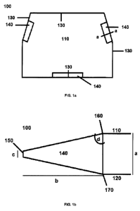
example embodiment of said platen is depicted in Figures 1a and 1 b.
Referring to Figure la and Figure lb, there is shown a DTG platen 100 having a
first planar
surface 110 and a second planar surface 120 opposite to the first planar
surface and
separated from the first planar surface in an axial direction and four
peripheral regions 130,
each of which extend from the first planar surface to the second planar
surface. The platen
embodied in Figures la and 1b enables a wrap-around pattern to be seamlessly
printed on
an item of clothing such as a pantie by use of three tapered edges 150, formed
in three
tapered regions 140 on three peripheral regions 130, two of which are opposing
(i.e. to
support the sides of the pantie), with the other peripheral region there
between (i.e. to
support the seat of the pantie).
CA 02997277 2018-03-01
8
WO 2017/044045
PCT/SG2016/050437
The embodiment of Figures 1a and 1 b may be particularly suitable for use in
the wrap-
around printing of an item of clothing, such as a pantie. When a pantie is
placed onto the
platen 100, the pantie becomes stretched over at least some of the peripheral
regions of the
platen, with the tapered regions being designed to come into close contact
with the stretched
portions of the pantie (i.e. sides and seat of the pantie), such that the
tapered edges 150
stretch the pantie even further at the point of contact. The pantie may then
be subjected to
DTG printing using the first surface of the platen 110, such that a first side
of the pantie is
covered, followed by printing on the second surface of the platen to provide a
pantie that has
a wrap-around and seamless pattern applied to it. In contrast, the use of a
similar platen
having non-tapered edges (e.g. flat or rounded edges) in DTG printing resulted
in a pantie
that has a wrap-around pattern applied to it, but where the seam caused by
printing on the
first and second sides of the pantie are visible.
It will be appreciated that a platen of the current invention may have any
suitable shape,
provided that the shape enables the seamless wrap-around DTG printing of an
item of
clothing, further the platen may be formed from a plurality of parts.
Figure 2a shows an example of a platen for printing on tank tops and/or vests.
The platen
250 has tapered regions 255 on the top edge and on the side edges. It will be
appreciated
that these tapered regions also comprise a tapered edge.
Figure 2b shows an example of platen formed from a plurality of parts for
printing on T-shirts.
The platen 260 is formed from three parts: a body part 270 and two arm parts
280. The body
part 270 is rectangular and has tapered regions 275 running along the full
length of the side
edges. The arm parts 280 have portions shaped to correspond to the arms of a T-
shirt and
have tapered regions 285 running along the top of bottom edges. It will be
appreciated that
these tapered regions also comprise a tapered edge.
In the embodiment of Figures 1a and lb, the platen is provided with four
peripheral regions
130, three of which contain tapered regions 140. It will be appreciated that
the tapered
platens of the current invention may contain one or more peripheral regions
(e.g. from one to
twenty, such as one to ten, such as from one to eight, such as from four to
six peripheral
regions) and that each of said peripheral regions may contain one or more
tapered regions
(e.g. from one to four, such as from one to two, such as one tapered
region(s)) that cover
whole or part of said peripheral region. For example, as shown in Fig. 2b,
each part of the
CA 02997277 2018-03-01
9
WO 2017/044045
PCT/SG2016/050437
platen has four peripheral regions, with two of these peripheral regions also
containing a
tapered region.
As shown in Figure lb (which is a cross-section taken along line a-a of Figure
la), the
tapered edges 150 may be double-sided. That is, the tapered region has two
tapers, one
extending from the first surface 110 and one extending from the second surface
120 that
meet to form the tapered edge 150. In other embodiments of the invention that
may be
mentioned herein, the tapered edges may be single sided, such that the tapered
region only
has one taper extending from the first surface 110 or the second surface 120
of the platen
100.
Referring to Figure 1 b, the platen has a maximum separation (a) between the
first and
second surfaces. In embodiments of the invention relating to tapered platens,
the maximum
separation of the first and second planar surfaces (a) may be from 0.5 mm to
150 mm (e.g.
from 0.5 mm to 50 mm, from 0.7 to 5 mm, or from 1 to 3 mm, such as 2 mm). In
particular
embodiments of the invention, the maximum separation of the first and second
planar
surfaces (a) may be 2 mm. While the embodiment in Figure lb depicts the first
and second
surfaces of the platen in a substantially parallel arrangement, it will be
appreciated that the
first and second surfaces do not need to be parallel, provided that these
surfaces enable a
continuous print to be applied to an item of clothing.
As shown in Figure lb, the tapered region(s) of the platen has a width (b),
which may be
measured from the beginning of the taper on the first 160 and/or second 170
surface to the
tip of the tapered edge 150. In embodiments of the invention relating to
tapered platens, the
width (b) of the tapered region(s) of the platen may be from 2 mm to 100 mm
(e.g. from 2.5
mm to 10 mm, or from 3 mm to 5 mm). In particular embodiments of the
invention, the width
(b) of the tapered region(s) of the platen may be 4 mm.
As depicted in Figure lb, the tapered edge 150 has a minimum thickness (c),
which is at the
apex of the tapered edge. In embodiments of the invention relating to tapered
platens, the
minimum thickness (c) of the tapered edge formed the tapered region(s) is from
0.1 to 5 mm
(e.g. from 0.5 to 0.5 mm, or from 0.2 to 0.4 mm). In particular embodiments of
the invention,
the minimum thickness (c) of the tapered edge may be 0.3 mm.
Finally, as shown in Figure lb, the taper formed in the tapered region has an
angle of taper
(d) that may be measured by reference to the beginning of the taper on the
first 160 and/or
second 170 surface. In embodiments of the invention relating to tapered
platens, the angle
CA 02997277 2018-03-01
wo 2017/044045
PCT/SG2016/050437
of taper (d) may be from 0.10 to 89.9 (e.g. from 45 to 85 , such as from 70
to 80 ). In
particular embodiments of the invention that may be mentioned herein, the
angle of taper (d)
may be 78 .
5 It will be appreciated that the dimensions and angles referred to
hereinbefore may be used
in any combination whatsoever and apply equally to single- and double-sided
tapered edges.
For example, the platen may have a double-sided tapered edge 150 and have a
maximum
separation of the first and second planar surfaces of 2 mm, a width (b) of the
tapered
region(s) of 4 mm, a minimum thickness (c) of the tapered edge of 0.3 mm and
an angle of
10 taper (d) of 78 .
The platens of the invention may be made using a metal such as aluminium or
stainless
steel. Alternatively, the platens may be made using a fiber glass or a
composite material
(e.g. a carbon composite material). It will be appreciated that combinations
of these
materials may be used to make portions of the platen. For example, stainless
steel may be
used to make the tapered regions of a tapered platen, with the remaining parts
of the platen
being made out of a carbon composite material. In particular embodiments of
the invention
that may be mentioned herein, the tapered platen may be made from aluminium.
For the
avoidance of doubt, platens of the invention comprising a means or apparatus
to transfer
part of an item of clothing disposed on the first surface of the platen onto
the second surface
of the platen may be made of similar materials.
In certain embodiments of the invention, the platen may be expandable. That
is, and as
exemplified by Figure 3a, the platen may contain sections 180, 181 that can
expand to better
fit the size of the item of clothing that is to be printed, such that the item
of clothing is
stretched more fully to enable a better wrap-around print. Platens according
to these
embodiments may contain one or more mechanisms 190 for expanding the sections
180,
181 to fit the item of clothing. This may be done manually or automatically
before fitting the
item of clothing to the platen 100. Alternatively, the platen may also contain
a force-
feedback mechanism to determine the ideal tension that the attached item of
clothing
requires for optimal printing. This force-feedback mechanism allows the platen
to
automatically adjust its size, and thereby the tension applied to the item of
clothing, to the
optimal level, thereby removing the need to manually determine the ideal
tension for the
attached item of clothing beforehand. In addition, the same force feedback
mechanism may
also be used to detect which sections of the platen are in contact with the
garment and then
expand only those sections, as it is only the sections that are in contact
with the item of
clothing that need to be expanded to enable optimal printing of the item of
clothing. This
CA 02997277 2018-03-01
11
wo 2017/044045
PCT/SG2016/050437
may reduce the number of different platens that are needed to print various
similar items of
clothing of differing sizes.
It will be appreciated that the expandable sections may operate using any
suitable means.
For example, the expandable sections may be controlled using springs or
pneumatics and
the extendible sections may be manually controlled, automated or self-
adjusting (e.g. by
spring-tension).
As shown in Figure 3a, the mechanisms 190 for expanding the sections 180, 181
do not
need to have the same width as the section 180, 181 it is attached to.
Provided that the
clothing is stretched taut at the points of contact with the sections 180, 181
(i.e. the tapered
regions 140) there is no need for the clothing to rest on a fully flat surface
on a platen. This
is because the platen may be used with a printer head that does not come into
physical
contact with clothing on the platen when a printed pattern is applied. For
example, when an
inkjet printer head is used, the inkjet droplets that come into contact with
the clothing to form
the pattern will not cause a distortion of the pattern provided that the
clothing is stretched
taut by the tapered regions 140 which are held in position by the expandable
regions. In
certain embodiments, all areas of the garment that are on the tapered edges
may need to be
supported along their entire length (e.g. for undergarments, the sides
connecting the
waistband and gusset should be supported along their entire length, as should
the edge of
the gusset).
The platens depicted in Figures 1 to 3a include a first and second surface
(e.g. 110, 120
according to Fig. 1 b), said surfaces may further comprise an absorbent
material. Said
absorbent material may be mounted, integrated or applied to the surfaces (110,
120) in order
to prevent wet ink that may be on the surfaces (110, 120) from transferring
onto the garment
while it is being removed from the platen, which may otherwise result in
smudging or spoiling
of the pattern.
In an embodiment, the platen may comprise a plurality of edge portions which
are configured
to hold a garment in a taut configuration. Figure 3b shows a platen 350 which
holds an item
of clothing 355 in a taut configuration for printing. The platen comprises
three segments 360
which are labelled A in Figure 3b and a truss 370 which is labelled B in
Figure 3b. The truss
may be spring loaded to hold the segments 360 in position and the garment in
the taut
configuration. The segments 360 each have an edge 365 which comprises a
tapered portion.
The tapered portions are arranged where the edge portions 365 of the segments
360 are in
contact with the item of clothing. As described above in relation to Figure
3a, the item of
CA 02997277 2018-03-01
12
WO 2017/044045
PCT/SG2016/050437
clothing is held taut by the edge portions of the segments and does not
require a surface
behind all of the area which is printed.
In alternative embodiments of the invention, the platen may use a means or
apparatus to
transfer part of an item of clothing disposed on the first surface of the
platen onto a second
surface of the platen in order to seamlessly print a wrap-around pattern on an
item of
clothing.
In certain embodiments, the means or apparatus to transfer part of an item of
clothing
disposed on the first surface of the platen onto the second surface of the
platen may be at
least one edge flipping mechanism attached to the peripheral region of the
platen. An
example of these embodiments is provided by Figure 4.
Figure 4 (A-C) depicts a platen having an edge flipping mechanism according to
the
invention with an item of clothing disposed thereon. In Figure 4A, the platen
200 has a first
planar region 211 and a second planar region 221 and has a peripheral region
230
extending from the first planar region to the second planar region. The
peripheral region
contains an edge flipping mechanism 235 attached thereto. The first planar
surface 210
may be formed by the first planar region 211 and part(s) of the edge flipping
mechanism 235
(e.g. as shown in Figure 4A) and the second planar surface is formed by the
second planar
region 221 and part(s) of the edge flipping mechanism 235 (e.g. the same
part(s) of the edge
flipping mechanism 235, as shown in Figures 4B and 4C). When an item of
clothing 114 is
placed on the platen of Figure 4A, a first portion 115 of a first face of the
item of clothing is
disposed on the first planar region 211 of the platen and second portions 116
of the first face
of the item of clothing are disposed on the flipping mechanism 235 disposed in
the
peripheral region 230 of the platen. A second face 117 of the item of clothing
is partly
disposed on the second planar region 221 and partly disposed on the flipping
mechanism
235. The flipping mechanism in Figure 4A is presented in a first
configuration, such that the
second portions 116 of the first face of the item of clothing 114 in contact
with the flipping
mechanism are substantially planar with the first portion 115 of the first
face of the item of
clothing located on the first planar region 211 of the platen 210, which
allows a continuous
print across the entire first face of the item of clothing. Following DTG
printing on the first
surface of the item of clothing 114, the flipping mechanism transitions to a
second
configuration as shown in Figure 4B, thereby bringing part 118 of the second
portions 116 of
the first face of the item of clothing 114 into planar alignment with the
second planar region
221 of the platen 200, such that a seamless wrap-around print may be
accomplished
following (optional) flipping of the platen, as shown in Figure 4C.
CA 02997277 2018-03-01
13
WO 2017/044045
PCT/SG2016/050437
As shown in Figures 4A and 40, the flipping mechanisms 235 extend above the
surface
defined by the first planar region 211 (Figure 4A) or the second planar region
221 (Figure
2B), such that the item of clothing 114 is stretched taut by the flipping
mechanisms 235 to
provide a substantially flat surface for printing on.
As will be appreciated, the actual number of flipping mechanisms 235 that are
employed
may vary depending on the item of clothing that is to be printed. These
flipping mechanisms
may operate in concert with one another or may operate independently,
depending on the
item of clothing to be printed. In common with the tapered platens described
hereinbefore,
the flipping mechanism may be attached to expandable sections of the platen.
In certain embodiments, the means or apparatus to transfer part of an item of
clothing
disposed on the first surface of the platen onto the second surface of the
platen may be at
least one toothed rotary actuator mechanism attached to the peripheral region
of the platen.
An example of these embodiments is provided by Figure 5.
Figure 5 (A-C) depicts a platen 300 having two toothed rotary actuator
mechanisms
according to the invention with an item of clothing disposed thereon. In
Figure 5A, the platen
300 has a first planar region 311 and a second planar region 321, and has a
peripheral
region 330 extending from the first planar region to the second planar region.
The peripheral
region 330 contains toothed rotary actuator mechanism attached thereto. The
first planar
surface 310 may be formed by the first planar region 311 and the rotary
actuator
mechanisms 335 in planar alignment with the first planar region 311 and the
second planar
surface 320 is formed by the second planar region 321 and the rotary actuator
mechanisms
335 in planar alignment with the second planar region 321. When an item of
clothing 114 is
placed on the platen of Figure 5A, a first face of the item of clothing is
disposed on the first
planar surface 310 of the platen, such that a first portion 115 is disposed on
the first planar
region 310 and second portions 116 of the first face of the item of clothing
are disposed on
the rotary actuator mechanisms 335 disposed in the peripheral region 330 of
the platen. A
second face 117 of the item of clothing is partly disposed on the second
planar surface 320
and partly disposed on the flipping mechanism 335. The rotary actuator
mechanisms in
Figure 5A are presented in a first configuration, such that the second
portions of the first face
116 of the item of clothing 114 in contact with the rotary actuator mechanisms
are
substantially planar with the first portion 115 of the first face of the item
of clothing located on
the first planar surface of the platen 310, which allows a continuous print
across the entire
first face of the item of clothing. Following DTG printing on the first face
of the item of
CA 02997277 2018-03-01
14
WO 2017/044045
PCT/SG2016/050437
clothing 114, the rotary actuator mechanisms transitions to a second
configuration as shown
in Figure 5B, thereby bringing part 118 of the second portions 116 of the
first face of the item
of clothing 114 into planar alignment with the second planar surface 320 of
the platen, such
that a seamless wrap-around print may be accomplished following (optional)
flipping of the
platen, as shown in Figure 5C.
As will be appreciated, the actual number of rotary actuator mechanisms that
are employed
may vary depending on the item of clothing that is to be printed. These rotary
actuator
mechanisms may operate in concert with one another or may operate
independently,
depending on the item of clothing to be printed. In common with the tapered
platens
described hereinbefore, the rotary actuator mechanism(s) may be attached to
expandable
sections of the platen.
The Embodiments shown in Figures 4 and 5 have been found to be particularly
effective
when used with fabric having a thickness of greater than 0.4mm.
The platens described hereinbefore may be attached to a system for DTG
printing. Said
system may be a DTG printing system comprising a direct to item of clothing
platen
according to any embodiment of the invention as described hereinbefore, a
template for
alignment of the platen and a printer. In certain embodiments of the
invention, the system
may further comprise a means or apparatus to automatically rotate the platen
from a first
position having a first surface exposed to the printer to a second position
having a second
surface exposed to the printer. It will be appreciated that the platens
described hereinbefore
as aspects of the invention (and their embodiments) may be an integral part of
the printer,
such that the platen form the printer bed. In such embodiments, the rotation
mechanism
described above may also be integrated into the printer, though this need not
be the case.
Figures 6a to 6d depict a system according to the current invention, wherein
the system
contains a platen 100 (which may be any platen according to the current
invention), a
template for alignment of the platen 410 and a printer (not depicted). In the
embodiment
depicted in Figures 6a to 6d, the system further comprises a mechanism 420
that
automatically rotates the platen from a first position having a first surface
exposed to the
printer to a second position having a second surface exposed to the printer.
The mechanism
420 comprises a holder 430 for the platen 100, a rotation device 440 and a
device 450 for
vertically removing and replacing the platen from the template 410. Following
printing of an
item of clothing on a first planar surface of a platen 100, the device 450
will lift the holder 430
and attached platen 100 off from the alignment template 410 to enable the
rotation device to
CA 02997277 2018-03-01
WO 2017/044045
PCT/SG2016/050437
rotate the holder and platen to expose the second planar surface of the platen
for printing.
Following rotation, the holder and platen are returned to rest within the
alignment template
and the item of clothing disposed on the second planar surface of the platen
100 is printed.
Thus, the system allows for a seamless wrap-around print of an item of
clothing.
5
As depicted in Figure 6d, the system may further comprise a template 410, upon
which the
platen and the holder rest. The template 410 can contain a custom cut-out
matched to the
shape of the platen to help prevent the platen from moving. The cut-out may
contain relief
sections that ensure that the item of clothing does not come into contact with
another
10 surface and smudge before curing. This helps to prevent non-uniform
sections of the item of
clothing (such as seams) creating an uneven surface on either side of the
platen.
Although not shown, the system may also include an integrated curing means or
apparatus
for curing an ink and/or an item of clothing after printing, such as an
apparatus to generate
15 hot air or an infra-red lamp.
It will be appreciated that the printing on the first and second planar
surfaces may be
accomplished simultaneously. Alternatively, the printing on the first and
second planar
surfaces may be accomplished sequentially, such that printing is accomplished
on the first
planar surface, followed by printing on the second planar surface.
As noted hereinbefore, the platen, the system and the processes described
above relate to
the manufacture of an item of clothing. Thus, there is also provided an item
of clothing
comprising an external surface comprising at least one wrap-around printed
pattern, wherein
the pattern does not exhibit a seam caused by printing. In particular
embodiments that may
be mentioned herein, the item of clothing may be obtained or obtainable by a
direct to
clothing printing process. Such an item of clothing may be distinguishable
over other items
of clothing printed using different techniques by, amongst other things,
simple hand-feel.
As mentioned hereinbefore, the item of clothing may be any thin and flexible
substrate that
has a 3-dimensional shape that may be used to cover whole or part of a 3-
dimensional
object. Such items of clothing may be pre-prepared and printed using the
platen and
techniques described hereinbefore to provide an item of clothing that has a
continuous,
wrap-around pattern disposed on a surface thereof, which would not otherwise
be
achievable, except by the individual printing of panels of material, followed
by hand
alignment and sewing.
CA 02997277 2018-03-01
16
WO 2017/044045 PCT/SG2016/050437
In summary, the platens, the systems and the processes described hereinbefore
enable one
to seamlessly print a pattern on a 3-Dimensional substrate using only two
printing operations
in 2-Dimensions (e.g. "front" and "back" of a substrate). In other words, the
technology
described herein enables the (potential) complete 3-Dimensional coverage of a
substrate
using only two printing passes.