Note: Descriptions are shown in the official language in which they were submitted.
NANO-LEVEL EVALUATION OF KEROGEN-RICH RESERVOIR ROCK
CROSS-REFERENCE TO RELATED APPLICATIONS
[0001] This application claims priority to U.S. Provisional Application No.
62/213,752, filed on September 3, 2015.
TECHNICAL FIELD
[0002] This disclosure relates to hydraulic fracturing, for example, of
hydrocarbon reservoirs.
BACKGROUND
[0003] Unconventional hydrocarbon reservoirs are reservoirs with trapped
hydrocarbons (for example, oil, natural gas, or combinations of them) in which
the
hydrocarbon mobility is limited. Extraction of hydrocarbons from such
reservoirs
typically involves increasing the mobility of the hydrocarbons, for example,
by
hydraulic fracturing. In hydraulic fracturing, a fracturing fluid (for
example, proppants
and one or more chemicals in an aqueous or non-aqueous base fluid) is flowed
through
the hydrocarbon reservoir. The fracturing fluid fractures the reservoir rock
to increase
mobility of the trapped hydrocarbons. Some unconventional reservoirs include
an
organic material called kerogen intertwined with the rock matrix.
SUMMARY
[0004] This disclosure relates to nano-level evaluation of kerogen-rich
reservoir rock.
[0005] Certain aspects of the subject matter described here can be be
implemented as a method. A micro-scale beam is formed from kerogen-rich
reservoir
rock. The beam includes reservoir rock and kerogen haying polymeric
properties. A
maximum dimension of the micro-scale beam is at most 1000 micrometer (gm). A
mechanical experiment that includes a tension test or a compression test is
performed
on the micro-scale beam. The mechanical experiment is imaged using a scanning
electron microscope (SEM) or a transmission electron microscope (IBM). A
material
parameter of the kerogen in the micro-scale beam is determined based on
results of the
mechanical experiment and images obtained responsive to the imaging.
1
CA 2997353 2019-07-19
CA 02997353 2018-03-02
WO 2017/040834
PCT[US2016/049971
[0006] This, and other aspects, can include one or more of the following
features. The mechanical experiment can be the tension test. The material
parameter
of the kerogen in the micro-scale beam can include a tensile strength of the
micro-
scale beam. The tension test can be a cantilever test. To perform the
cantilever test, a
force of the order of micro-Newtons can be applied on a free-end of the micro-
scale
beam. To determine the material parameter, a bending of the cantilever
responsive to
the force can be measured. The force can be applied at a rate of displacement
of
substantially between 1 nm/s to 100 nm/s. The rate of displacement can be
substantially between 5 nm/s to 20 nm/s. The load can be applied until the
micro-scale
to .. beam fails. The mechanical experiment can be the compression test. The
material
parameter can include a compressive strength of the micro-scale beam. To
perform
the compression test, the micro-scale beam can be loaded under a compressive
load of
the order of micro-Newtons at a specified displacement and rate until failure
of the
micro-scale beam. To perform the mechanical experiment, micro-scale beam
loads,
micro-scale beam displacement data and time data can be collected as the
mechanical
experiment is being performed. The micro-scale beam can be formed using a
focused
ion beam. The micro-scale beam can be a pillar with a substantially square or
circular
cross-section. To image the mechanical experiment using the SEM, multiple SEM
images of the micro-scale beam can be captured at different time instances
during the
mechanical experiment. To image the mechanical experiment using the SEM, the
micro-scale beam can be positioned inside the SEM. Energy dispersive X-Ray
spectroscopy (EDS) can be performed on the micro-scale beam while the micro-
scale
beam is inside the SEM. Based on results of the EDS, a chemical composition of
the
micro-scale beam can be determined. The EDS can be performed on the micro-
scale
beam before, during or after the mechanical experiment. The EDS can be
performed
after the micro-scale beam has failed in response to the mechanical
experiment.
Before forming the micro-scale beam, the kerogen-rich reservoir rock can be
treated
with a fluid configured to break down kerogen in the rock sample. An effect of
the
fluid on the kerogen in the rock sample can be determined based on the
material
parameter of the kerogen in the micro-scale beam. The micro-scale beam can
include
multiple, stacked shale bedding planes. The mechanical experiment on the micro-
scale
beam can be performed either parallel to or perpendicular to the multiple
stacked shale
bedding planes. Compression tests on pillars can be performed with the force
applied
2
either parallel or perpendicular to the bedding planes, resulting in two
different pillar orientations.
Tensile tests on beams can be performed with the force applied either parallel
or perpendicular to
the bedding planes, resulting in three different beam configurations. For
example, if the bean is
configured such that a three is applied perpendicular to the bedding planes,
the tension
experienced in the beam runs parallel to the bedding planes.
[0006A] In a broad aspect, the present invention pertains to a method
comprising
treating kerogen-rich reservoir rock with a fluid configured to break down
kerogen in the
reservoir rock the kerogen having polymeric properties forming a micro-scale
beam from the
kerogen-rich reservoir rock. The micro-scale beam comprises the reservoir rock
and the kerogen
having properties wherein a maximum dimension of the micro-scale beam is at
most 1000
micrometer (pm). A mechanical experiment is performed on the micro-scale beam,
the
mechanical experiment comprising a tension test or a compression test. The
mechanical
experiment is imaged using a scanning electron microscope (SEM) or a
transmission electron
microscope (TEM), and a material parameter of the kerogen in the micro-scale
beam is
determined based on results of the mechanical experiment and images obtained
responsive to the
imaging.
[0006B] In a further aspect, the present invention embodies a method
comprising
treating kerogen-rich reservoir rock with a fluid configured to break down
kerogen in the
reservoir rock, the kerogen having polymeric properties. A mechanical
experiment is performed
on a micro-scale beam formed from the treated kerogen-rich reservoir rock. The
mechanical
experiment is imaged using a scanning electron microscope (SEM) or a
transmission electron
microscope (TEM). A material parameter of the kerogen in the micro-scale beam
is determined
on results of the mechanical experiment and images obtained responsive to the
imaging, an effect
of the fluid on the kerogen in the reservoir rock is determined, based on the
determined material
parameter.
[0007] The details of one or more implementations of the subject matter
described in
this specification are set forth in the accompanying drawings and the
description below. Other
features, aspects, and advantages of the subject matter will become apparent
from the description,
the drawings, and the claims.
3
CA 2997353 2020-01-08
BRIEF DESCRIPTION OF THE DRAWINGS
[0008] FIG. lA is an image of porous fibroblast and porous collagen.
[0009] FIG. 1B is an image of porous kerogen.
[00010] FIG. 2A is a schematic of an example testing
apparatus inside
an SEM.
[00011] FIG. 2B is a flowchart that shows an example
process for
determining properties of a micro-scale rock sample.
[00012] FIGS. 3A-3I are scanning electron microscopy (SEM)
images of
kerogen-free shale.
[00013] FIG. 4 is a schematic of complex layering of
illite and kerogen
in kerogen-rich shale.
[00014] FIGS. 5A and 5B are SEM images of an example shale
formation including kerogen-rich shale.
[00015] FIGS. 6A-6D are SEM images and a schematic diagram
of
kerogen-free shale.
[00016] FIGS. 6E-6H are SEM images and a schematic diagram
of
kerogen-rich shale.
[00017] FIG. 7 is a plot of stress versus strain and
load/unloading small
strain Young's Moduli.
3a
CA 2997353 2020-01-08
CA 02997353 2018-03-02
WO 2017/040834
PCT/US2016/049971
[00018] FIGS. 8A and 8B are SEM images of shale.
[00019] FIG. 9A is a schematic diagram of a FIB-SEM sample.
[00020] FIG. 9B is a SEM image of a FIB-SEM sample.
[00021] FIG. 9C is a SEM image of a cantilever load being applied
on a
FIB-SEM sample.
[00022] FIG. 9D is a schematic diagram of a cantilever load being
applied on a FIB-SEM sample.
[00023] FIG. 10A is a SEM image of a micro-pillar manufactured
using
the FIB-SEM technique.
[00024] FIG. 10B is a schematic diagram showing dimensions of a
micro-pillar.
[00025] FIG. 10C is a SEM image of a micro-pillar on which load is
applied.
[00026] FIG. 11 shows a load versus displacement curve for four
micro-
is beams.
[00027] FIGS. 12A-12H show load versus displacement at multiple
time
instants during progressive cantilever loading of a micro-beam.
[00028] FIGS. 13A and 13B are detailed load versus displacement
curves showing early failures with linear loading and rebounding slopes
isolated.
[00029] FIG. 14A is an SEM image of a cantilever micro-beam KRS
with organic rod-like material.
[00030] FIG. 14B is a SEM image of Woodford shale.
[00031] FIG. 14C is a full load versus displacement curve.
[00032] FIGS. 15A and 15B show top views of a cantilever micro-beam
with total breakage of the granular shale matrix at the support stage.
[00033] FIGS. 16A-16D show a numerical modeling of a cantilever
micro-beam behavior.
4
CA 02997353 2018-03-02
WO 2017/040834
PCT/US2016/049971
[00034] FIG. 17 is a load versus displacement curve showing strain
hardening before a sharp snap at failure.
[00035] FIGS. 18A-18F show load versus displacement progress
between two points.
[00036] FIGS. 19A and 19B are two load versus displacement plots of
micro-cantilever beam tests.
[00037] FIGS. 20A-20D show load versus displacement curves and
SEM images before and after brittle failure of a sample.
[00038] FIGS. 21A and 21B show moduli of ruptures of granular shale
(T3) compared to kerogen elastomer cross-linked polymer in Ti and T2.
[00039] FIG. 22A is a SEM image of a micro-pillar pre-loading
overlaid
with energy dispersive X-ray spectroscopy (EDS) map.
[00040] FIG. 22B is the EDS of the micro-pillar displayed and
superimposed.
[00041] FIG. 23A is a plot of stress versus strain in a micro-pillar
compression test.
[00042] FIG. 23B is a SEM image of the micro-pillar after failure.
[00043] FIG. 23C is an EDS map of the micro-pillar superimposed
showing the intact shear band plane pre-failure.
[00044] FIGS. 24A-24F are SEM images of failed micro-beams.
[00045] FIG. 25 shows an example of a fracture treatment for a
well.
[00046] FIG. 26A-26B are schematic diagrams of indenter tips at
different orientations relative to shale bedding planes for a tension and
compression
test respectively.
[00047] Like reference numbers and designations in the various
drawings indicate like elements.
5
CA 02997353 2018-03-02
WO 2017/040834
PCT/US2016/049971
DETAILED DESCRIPTION
[00048]
Unconventional reservoirs such as organic rich shale have been
the subject of micro- and nano-mechanical characterization using the advances
of
nanotechnology. Shale and mudstones were tested using a nano-indenter while
searching for the micromechanical characterization of shale rocks. One study
was
interested in GEOGENOMINGTm clay and mudstones for applications in wellbore
drilling stability and fault gauge micro-mechanics. Another study attempted to
relate
kerogen stiffness and anisotropy to its maturity for organic rich source
shale. In these
efforts, indenting at nano- and micro-scales, thus isolating mineral phases
from the
kerogen ones, it was concluded that kerogen stiffness is isotropic. Kerogen-
free shale
(KFS) was found to be strongly transversely isotropic at nano- and micro-
scales.
However, the kerogen stiffness and the percent volume phase, vis-à-vis the
rest of the
shale minerals, reduced the shale anisotropy in many instances in ultrasonic
pulse
velocity measurements. These early nano-indentation studies were attempts to
measure the mechanics at the smallest possible "porous unit" of a mudstone
rock, that
is, attempting to identify what is the scale of the Representative Elementary
Volume,
REV, of fluid filled shale composites. Their shale samples used in these early
experiments contained only "trace" levels of organic material, which means the
organic matter had little effect on the overall mechanical response (the total
clay
content was more than 75 wt%).
[00049] Further nano-
indentation studies were conducted on the organic-
rich Woodford shale (<30% clay; 10-18% kerogen) allowing the observation of
the
effects that the kerogen matrix has on the overall mechanical properties of
KRS,
including the effects on elastic and plastic behavior. The upscaling of poro-
mechanical anisotropic parameters of KRS from nano-indenter characterization
to
macro-rock mechanics laboratory measurements and to field logging tools has
also
been the subject of certain studies.
[00050] Very little
light has been shed on how the KRS fails in tension
(such as in hydraulic fracturing) or in compression (such as in drilling) at
the micro-
and nano-scales as well as the effects of the kerogen polymer nature and its
spatial
distribution on the overall shale matrix. Classical rock mechanics testing on
KRS in
both tension and compression have been performed with respect to deposition
modes
6
CA 02997353 2018-03-02
WO 2017/040834
PCT/US2016/049971
both parallel and perpendicular to the bedding planes of the Woodford shale.
However,
these ASTM and ISRM standard test methods did not reveal any novelties about
the
failure mechanisms of the Woodford KRS.
[00051] This
specification describes loading and failing KRS using
micro-beams and micro-pillars. In some implementations, micron-sized
geometries of
preserved Woodford shale were manufactured via focused ion beam (FIB) under
SEM,
then loaded to failure via nano-indentation under the SEM. In some
implementations,
the loading and failing of KRS using micro-beams and micro-pillars can be
performed
in situ within a transmission electron microscope (TEM). Manufacturing
techniques
used to manufacture the test samples can include, for example, lithographic
techniques, reactive ion etching, or other semiconductor manufacturing
techniques.
The associated forces (loads) in micro-Newtons and failures at displacements
in the
range of hundreds of nanometers have shown the true nature of the failure
mechanisms, in compression and tension, of this composite polymer-rich porous
material. It was observed that the organic phase in the tensile mode acts like
a cross-
linked polymer with substantial tensile strength, and a very large modulus of
rupture
when compared to the brittle behavior of granular shale minerals. This
composite
material behavior is not new to our scientific community, but kerogen tensile
elastic
strength has eluded our community to date. This type of behavior in natural
material is
also observed when measuring bone strength due to the presence of porous
collagen/fibroblast as cross-linked material. The collagen/fibroblast porous
nature that
is embedded in bones, mimic the overall composite behavior in tension, as the
porous
kerogen spatially distributed within the KRS in the clay and non-clay mineral
matrix
as shown in FIGS. lA and 1B. Also, organic content in bio-composites similarly
augment by order of magnitudes the fracture energy of their minerals.
[00052] FIG. 2A
shows an example test apparatus 250 for determining
properties of a micro-scale rock sample 258. A nano-indenter 254 is placed
within a
scanning electron microscope 252. A rock sample 258 is located within the nano-
indenter 256 and can be watched while experiments are taking place. The nano-
indenter tip 256 can be a variety of shape, for example, hemispherical or flat-
bottomed.
7
CA 02997353 2018-03-02
WO 2017/040834
PCT/US2016/049971
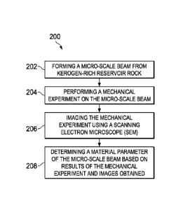
[00053] FIG. 2B shows
an example method 200 for determining
properties of a micro-scale rock sample. At 202, a micro-scale beam is formed
from a
kerogen-rich reservoir rock. At 204, a mechanical experiment is performed on
the
micro-scale beam. At 206, the mechanical experiment is imaged using a scanning
electron microscope (SEM). At 208, a material parameter of the micro-scale
beam is
determined based on results of the mechanical experiment and images obtained.
[00054] This
specification also describes a preliminary two-dimensional
numerical model built in order to model the loading and displacement curve in
the
composite shale of one of the micro-beams. The emphasis was on the kerogen
volume
and its intrinsic characteristics at the micro-cantilever beam support, as
observed in-
situ, compared to the fracture propagation and the strain softening potential
of beams.
The two dimensional model did capture the micro-beam load displacement curve
and
its corresponding modulus of toughness.
[000551 The Nano Granular Nature of Shale and Its Polymer Kerogen
000561 All shale source rock
reservoirs have the major components of
non-clay minerals like quartz, feldspar and plagioclase, QFP, clays such as
illite, mica,
smectite, and finally organic matter such as kerogen, and bitumen where the
oil and
gas reside. An unconventional shale reservoir with 5 wt% kerogen (-10 vol%) is
considered kerogen rich. In this specification, all the various types of
organic matter
described above are considered to be components of kerogen, since what is of
interest
is the mechanics of failure of the composite organic-rich shale, and not the
stage of
maturity of the organic matter or the reservoir potentials. In this nano-
/micro-
mechanics approach, the isolated contribution of each KRS component and the
role it
plays in the intertwined phenomena of minerals and kerogen matrices and the
different
mechanisms of failure were observed. This specification describes
interpretations of
the experimental results and provides a preliminary numerical model based on
the
likely percent weight that the interlaced polymer kerogen contributes to the
overall
shale sample behavior.
00057] Nano-
indentation on Kerogen Free Shale (KFS): An Intrinsic
Transverse Isotropic Granular Material
8
CA 02997353 2018-03-02
WO 2017/040834
PCT/US2016/049971
[000581 FIGS. 3A, 3D
and 3G are SEM images of a first KFS sample.
The term "x3" in FIGS. 3A and 3D indicates that the sample is viewed parallel
to the
bedding plane. The term "xl" in FIG. 3G indicates that the sample is viewed
perpendicular to the bedding plane. FIGS. 3B, 3E and 3H are SEM images of a
second
KFS sample. FIG. 3B indicates that the sample is viewed perpendicular to the
bedding
plane. FIGS. 3E and 3H indicate that the sample is viewed perpendicular to the
bedding plane. FIGS. 3C, 3F and 31 are SEM images of a third KFS sample. FIG.
3C
indicates that the sample is viewed perpendicular to the bedding plane. FIGS.
3F and
31 indicate that the sample is viewed perpendicular to the bedding plane. The
images
show sub-micron clay particles ranging between 10 nm and 100 nm in thickness
in a
variety of forms and shapes, ranging from sheet packages (Shale 1), to wavy
flake
structures (Shale 2) and highly pressed and crushed sheets (Shale 3).
1000591 Nano-
indentation has been used to test small shale samples with
only "trace" of kerogen present, where the volume percent is too small to
alter the
mechanical behavior of the shale at any scale. These shale samples studied
contained
75-80 wt% clay. The shale samples were tested both parallel and perpendicular
to
their bedding plane with thousands of load versus displacement curves
collected,
which led to identifying the nano-scale material volume of anisotropy in non-
organic
shale. For example, a tensile strength in a direction parallel to the bedding
plane is
equivalent to pulling a composite network along its edges in a direction
parallel to a
surface of the composite network. In another example, a tensile strength in a
direction
perpendicular to the bedding plane is equivalent to pulling the composite
network
along its edges in a direction perpendicular to the surface of the composite
network.
The response of the composite network to the same tensile force in two
different,
orthogonal directions is measured. These observations concluded that the
tested shale
shown in FIGS. 3A-3I, are granular in nature and their anisotropic nano and
micromechanical properties depends on their particle to particle contact,
their packing
densities, and the various stiffness of their mineral properties.
1000601 The KFS
properties varied from one sample to the next, and the
clay and QFP compositions varied along with their respective porosities. The
granular
cohesionless system of earth materials, in particular, with compaction
histories,
-memory" and compacted densities, are very complex processes when it comes to
their
9
CA 02997353 2018-03-02
WO 2017/040834
PCT/US2016/049971
mechanical properties. Clay-bearing sedimentary rocks, such as shale, formed
under
even more complex geological processes, are mechanistically even more complex.
The role of their mineral composition in the overall mechanical property
characterization has been the subject of many studies. The KFS in the SEM
images in
FIGS. 3A-3I were nano-indented, in-bedding and perpendicular to bedding, and
exhibited clear mechanical anisotropy at these scales without any effects from
organic
matter.
[00061] The
Intertwined View of Kerogen Rich Shale (KRS) as a
Transverse Isotropic Composite
[00062] Shale anisotropy has
been known and modeled in our
mechanistic approaches from early on, as a fluid saturated porous media
exhibiting
transverse isotropy likely due to mode of deposition, bedding planes, micro-
fractures
or micro- and nano-clay shape or both and packing porosity as described in the
above
section. Experimental results, particularly acoustic measurements, provided
early
evidence of shale transverse anisotropy. However, for source rock KRS, the
acoustic
measurements have attributed shale anisotropy not only to fractures and
bedding
planes but also to the presence of kerogen interlayered with illite clay
minerals as
shown in FIG. 4. Previous research has paved the way for geomechanics
anisotropy
modeling of shale in wellbore stability analysis, reservoir compaction
simulation, and
shale laboratory testing characterization. However, kerogen could not be
definitively
pinned as the culprit for anisotropy at all scales. KFS has shown intrinsic
anisotropy
and in many instances even higher than KRS anisotropy at micro and macro
scales.
[00063] However,
when the conceived structure of clay and kerogen
combined as shown in FIG. 4, is taken to failure by tensile or compressive
forces, it
will be extremely hard to imagine let alone to model the various phases and
how will
they interact with the rest of the shale matrix. Kerogen as a polymer has
intrinsic
mechanical properties for elastic behavior and its own material properties at
plastic
yield. The limitation of an isotropic plastic model to be able to model the
plastic yield
from nano-indentation of the KRS has been addressed in previous research. The
anisotropic stiffness parameters and the nature of organic free and or organic
rich shale
and their intrinsic transverse isotropy from nano- to macro-scales have been
addressed
in detail elsewhere.
CA 02997353 2018-03-02
WO 2017/040834
PCT/US2016/049971
[000641 Example of a shale formation
[000651 This
specification describes nano- and micro-scale Woodford
KRS taken to failure in tension and compression. As background, a brief
description
of the geological setting is provided below.
[000661 The Woodford shale
formation, deposited during the lower
Missisipian and upper Devonian period in an anaerobic marine environment, is
found
throughout the central part of the U.S. Midwest. The formation has long been
known
to be one of the major source rocks of the region, and for the past decade it
has been a
great source of energy in gas and oil. Woodford shale has high quartz content
as
113 revealed by X-
ray diffraction (XRD) analysis, greater than 20% in total porosity, and
permeabilities ranging from 80-40 nano-Darcys. While it is typical of source
rock
shale to have kerogen dispersed in its structures, the Woodford shows
pronounced
intertwined kerogen strings shown in two-dimensions when compared to the
overall
granular mineral matrix. FIGS. 5A and 5B show very complex shapes of organic
material (kerogen) in the Woodford. The SEM images of Woodford shale highlight
the intertwined nature of minerals and kerogen (black polymer-like ribbons).
The
scale of the ribbons is tens of micro-meters.
[000671 The
heterogeneity of the Woodford KRS, like all source shale,
is due among many reasons, to local non-clay minerals such as quartz, calcite
and
pyrite, and clay minerals intertwined with kerogen string-shaped components at
nano,
micro and macro levels. Similar to the multiscale structure of KFS a
complementary
KRS multiscale mechanistic structure, based on SEM images, is shown in FIGS.
6A-
6H.
[00068] FIG. 6A is a
macro-level SEM image of kerogen-free shale, for
example, porous clay-silt inclusion composite, taken at a scale of greater
than 10-3 m.
FIG. 6B is a micro-level SEM image of a portion of the kerogen-free shale
shown in
FIG. 6A taken at a scale of greater than 10-5 m. FIG. 6C is a sub-micro-level
SEM
image of a portion of the kerogen-free shale shown in FIG. 6B taken at a scale
of
greater than 10-7 m. FIG. 6D is a schematic drawing of a portion of the
kerogen-free
shale shown in FIG. 6C drawn at a scale greater than 10-9 in. FIG. GE is a
macro-level
SEM image of kerogen-rich shale, for example, layered composite shale with
clay/quartz mix (light gray) and organic layers (dark gray), taken at a scale
of greater
11
CA 02997353 2018-03-02
WO 2017/040834
PCT/US2016/049971
than 10-3 m. FIG. 6F is a micro-level SEM image of a portion of the kerogen-
rich
shale shown in FIG. 6E taken at a scale of greater than 10-5 m. The image
shows
kerogen and micro-pores distributed throughout the mineral matrix. FIG. 6G is
a sub-
micro-level SEM image of a portion of the kerogen-rich shale shown in FIG. 6F
taken
at a scale of greater than 10-7 m. The image shows nano-porous minerals
interwoven
with nano-porous organic matter. FIG. 6H is a schematic drawing of a portion
of the
kerogen-rich shale shown in FIG. 6G at a scale greater than 10-9 m. The
schematic
diagram shows elementary components, namely, clays such as illite, smectite,
etc., and
organic molecules, for example, kerogen.
[000691 In compiling this micro
to macro structure with micro-bedding
planes and micro-fractures shown at level II, the failure mechanisms of such
composite
are very- complex. For example, in tensile loadings, the polymer and rubber-
like
kerogen embedded in the shale matrix, at all scales, will augment the tensile
rupture
(modulus of toughness) of the granular fractured structure matrix.
[00070] Macro-scale testing of
shale in light of kerogen content and
composite nature of KRS
[00071] In this
section, the data and the macro-scale testing conducted
on the same preserved Woodford is revisited for many details that previously
were
missed since kerogen content, and the composite nature of KRS, was not
considered in
the previous data interpretations. In the previous study, only the
classical
geomechanics approaches were considered with corresponding mechanical
parameters.
FIG. 7 shows the loading and unloading up to failure of an ASTM 2" x 4"
standard of
the preserved Woodford KRS in an unconfined compressive loading configuration.
The unconfined compressive strength value is more than 5000 psi in compression
with
the large sample deformation close to 0.8% strain. The axial and radial
stress/strain
curves show the slightly plastic yield deformation starting at the third round
of
loading/unloading (the straight dotted line on the axial deformation)
eventually
masked by piece-wise partly linear slope to eventually undergo brittle
failure. Yet the
small strain Young's moduli shown in Table 1 (below) at the third and fourth
cycles
were unaffected by the stress yield. This bilinear elastic behavior, followed
by a brittle
failure, is intriguing and is difficult to explain, considering single
granular phase
behavior.
12
CA 02997353 2018-03-02
WO 2017/040834
PCT/US2016/049971
Axi
al Stress ycling
(psi) (Mpsi)
125 1
0 .57
230 1
0 .53
370 1
0 .62
550 1
0 .62
Table 1 ¨ Young's Modulus for small strain measurements for Woodford shale
sample.
[00072] Another observation is that the Young's moduli measured at
loading/unloading cycles were more than 50% larger than the overall Young's
.. modulus of the full testing load range shown in Table 2.
Sample 166-2 to 166-6
Strength 1
(psi) 800
6
E (kpsi) 60
0.
3
Table 2 ¨ ASTM measurements.
[00073] The value of the dynamic Young's moduli calculated from the
compressional and shear waves velocities were 10-15 % different from the
loading/unloading small strain cycles, thus confirming the granular porous
nature
behavior of this shale when undergoing compressive small loads.
00074] Recent data summarizes another large campaign of nano-
indentation testing on these same horizons of the preserved Woodford KRS. The
full
13
CA 02997353 2018-03-02
WO 2017/040834
PCT/US2016/049971
sweep of tests on shale samples, both parallel and perpendicular to beddings,
showed
that the organic matters have anisotropic stiffness, and much smaller
stiffness values
than reported previously in the plane parallel to beddings. Recent research
indicated
that damage may have occurred during cutting and polishing, due to heat,
altering the
inherent kerogen anisotropy, and that the kerogen rebound when load was
removed
and some permanent deformation (plastic) remained as evidenced by the
indentation
imprint. FIGS. 8A and 8B provide much clearer SEM images that, illustrating
clearly
what was called "...indentation into a highly heterogeneous region," showing a
large
percentage of the organic matter and minerals and being simultaneously
indented.
to FIG. 8A shows a polished surface with organic material which
includes 1 um-sized
diameter pyrite framboids, silicate, clays, etc.. FIG. 8B shows a similar
region which
has been indented. The final area projected after the indent imprint is
roughly 450
mm2. The preliminary conclusion of these above described experiments is that
the
organic matter in the source shale needs to be somehow reinvestigated within
the
overall framework of the porous shale.
[00075] Example of an
experiment to prepare a kerogen-rich shale
(KRS) sample
[00076] Focused Ion
Beam (FIB) ¨ Scanning Electron Microscopy
(SEM) sample preparation of specific geometries such as micro-pillars and
micro-
cantilevers of KRS are described here. In some implementations, four micro-
beams
and three micro-pillars were milled and prepared for in-situ testing.
I000771 Example of
cantilever testing KRS micro-beams using a pico-
indenter (PI-85) in the FIB-SEM
[00078] A sample with
dimensions of 1 cm x 1 cm x 0.4 cm was cut
from a preserved Woodford KRS core. A sharp 90 edge was created by mechanical
polishing using standard silicon carbide paper up to 4000 grit followed by
polishing
with 1 tun diamond grit. A Quanta 3D field emission gun (FEG) with FIB-SEM was
used to prepare the micro-beams. FIB surface milling was used to clean the
surface
for better sample imaging as well as to prepare the desired micro-geometries.
Four
micro-beams were manufactured using the FIB procedure according to the S.G.
Roberts method. While the beams in this experiment were manufactured according
to
the S.G. Roberts method, other manufacturing techniques, such as lithographic
14
CA 02997353 2018-03-02
WO 2017/040834
PCT/US2016/049971
techniques, reactive ion etching, or other semiconductor manufacturing
techniques,
can be used. Each shale micro-beam was shaped by cutting trenches on all three
sides
with widths of 20 gm and depths of 10 gm using a 15 nA beam current, resulting
in a
U-shaped trench. The geometry was then refined by applying a 1 nA beam
current.
Afterwards, the sample was tilted to 45 along the length axis to shape the
cantilever.
The base of the cantilever was undercut from both sides using a 3 nA beam
current.
The resulting cantilever geometry is shown schematically in FIG. 9A, with the
corresponding SEM images of three of the four micro-cantilever beams shown in
FIG.
9B. It should be noted that this sample size is still well above the REV of
composite
shale. As shown in FIG. 26A and F1G.26B, the beams can be manufactured with
varying orientations relative to the shale bedding planes, such as
perpendicular to the
force of the indenter tip 256 or parallel to the force of the indenter tip
256.
Manufacturing the beams at the varying orientations can allow studying
anisotropy of
the beams and upscaling the anisotropy to larger KRS samples.
[00079] A Hysitron Pi-85 Pico-
indenter was used to load the micro-
beams under displacement control mode, at a rate 10 nm/s. The indenter tip is
a flat
circular punch geometry, with a diameter of 5 gm. All loading experiments were
performed in situ under the SEM, where loading of the micro-cantilever beams
continued until failure. The indenter tip was placed at the end of the beam,
centered
along the y-axis as shown in the SEM in FIG. 9C. Load and displacement data
were
collected in real-time. FIG. 9D is a schematic diagram showing the micro-
experiment
with dimensions.
[00080] During the
experiment, a force (micro-Newtons) is applied to
the beam or pillar through the nano-indenter tip. As the force is applied, the
beam or
pillar deforms (meaning the indenter tip is displaced in nanometers). Both the
force
and displacement are captured by the nano-indenter software throughout the
experiment. Typically the rate of displacement is controlled (for example, 1-
100 nm/s,
5-20 nm/s or other rate of displacement) while the force is applied to such a
degree as
to maintain this displacement rate. Because this experiment is performed
inside a
scanning electron microscope (SEM), the fourth parameter captured (beyond
force,
displacement, and time) is an SEM image. In fact, the SEM images are captured
throughout the entire loading experiment as a movie of the entire experiment.
Finally,
CA 02997353 2018-03-02
WO 2017/040834 PCT/US2016/049971
additional analysis of the micro-beam and micro-pillar can also be performed
with
energy dispersive x-ray spectroscopy (EDS) while the sample is inside the SEM.
This
measurement provides the chemical (elemental) composition of the sample. It
can be
performed pre-loading, post-failure, or in some configurations, during the
loading.
[00081] Earlier, it was
illustrated from macro measurements on 2x4"
samples that the loading/unloading Young's Moduli differed from the large
strain
Young's Modulus by more than 50 % but are within 10% of the dynamic
measurements. Also, the values of Young's moduli obtained by nano-indentation
on
porous multiphase material are close in value to the small strain deformation
and to the
ultra-pulse velocity measurements. However, when a solid metallic beam with
micron-sized dimensions is subjected to loading, there is strong evidence that
size
effects come into play. This phenomenon has been elaborated on and theoretical
results have been obtained corresponding to an intrinsic length scale effects
on the
overall deflection, w, of a solid micro-cantilever beam with intrinsic length
scale, frE
that is found by calibrating a typical beam thickness with the experimental
suite of
results. The expression relevant to the experiments described here is shown in
Equation (1).
w (1)
j000821 In Equation
(1), / is the moment of inertia for the micro-
cantilever beam prismatic cross section. The length of the cantilever beam
runs along
the x-axis, and the position of the indenter tip along that axis is denoted as
x. It is
assumed that that x¨L because they are very similar. The parameter E is the
Young's
modulus, which is a measure of the stiffness. It is reported in units of GPa.
Equation
(1) provided satisfactory results when used to analyze experimental
measurements.
However, Equation (1) may need to be modified for a granular multi-porous
structured
material intertwined with organic matter. The discovery is that when we
assumed /FE
= 0 for Equation (1), where it turns into the expression for the classical
theory of
beams, the micro-cantilever beam Young's moduli was within 10% error from the
ones shown in Table 1. Indeed, results calculated from the classical theory
for the
stiffness expression (Equation (2)) match the nano-indenter results as well as
the small
16
CA 02997353 2018-03-02
WO 2017/040834 PCT/US2016/049971
strain loading/unloading of FIG. 7, and the corresponding ultra-pulse velocity
measurements using the compressional and shear wave velocities.
FIP
(2)
awl
[000831 Example of
compression testing KRS micro-pillars using a pico-
indenter (PI-85) in the FIB-SEM
[00084] As shown in
FIG. 10A, square micro-pillars with minimal taper
were manufactured in the FIB instrument (Quanta 3D FEG) with successively
lower
beam currents (5 nA down to 0.3 nA at 30 kV) to achieve the geometries shown
in
FIG. 10B. Alternatively, the micro-pillars can have other cross-sectional
shapes. For
1() example, the
micro-pillars can be round. The milling procedure followed the methods
of earlier works. To achieve the square geometry, the sample was tilted by 2
with
respect to the incident ion beam in order to mill the side surfaces of the
pillar by
grazing incident ions. The aspect ratio (micro-pillar height divided by width)
was set
close to three to one. These dimensions may vary slightly, eventually, if
these tests are
to be standardized for porous natural material such as shale. While the beams
in this
experiment were manufactured in the FIB instrument, other manufacturing
techniques,
such as lithographic techniques, reactive ion etching, or other semiconductor
manufacturing techniques, can be used.
[00085] FIG. 10C
shows a load being applied to a micro-pillar. A
different Hysitron indenter was used to uni-axially compress the micro-pillars
using a
diamond flat punch tip indenter (60 conical, 10 gm diameter flat end) as
shown in
FIG. 9C. The micro-pillars were loaded at a predetermined displacement rate
until
failure. FIG. 9B provides a schematic of the micro-pillar with dimensions of
b, h, and
L and applied force P. The compression of the micro-pillar samples under the
nano-
indenter can be described by the classic compressional stress-strain
relationship.
[00086] Micro-Beam Testing
[00087] FIG. 11 shows
a load Ay's displacement curve for four micro-
beams. Four micron-sized beams were milled to load and fail Woodford shale in
tensile mode. Each test was performed inside the SEM with a small-scale nano-
indenter, and movies of the loading and failure were captured in real time
during the
17
CA 02997353 2018-03-02
WO 2017/040834
PCT/US2016/049971
experiment. This unique setup provided not only the ability to load and
fracture
micro-scale KRS structures but also the advantage of visualizing the
initiation of a
fracture in the tensile zone, then propagation, and ultimate failure while
correlating
these phenomena with the force-displacement plots collected during the
experiments.
The load-displacement curves (FIG. 11) show that samples T3 and T4 failed in
brittle
modes while samples Ti and T2 showed plastic deformation before failure.
Samples
Ti and T2 showed strain softening and strain hardening behavior, respectively
before
ductile failure. Samples T3 and T4 showed brittle failure with little or no
yield.
1000881 The load-
displacement curves captured from loading at the tip
of the micro-cantilever beams of equal prismatic dimensions can be compared
directly.
The areas under their respective force-displacement curves are proportional to
the
energies required to break the beams in a tensile mode (as shown in FIG. 21A
and
FIG. 21B). The higher the energy, the lower the fracturability of the rock
(more
ductile). Higher kerogen content within the beam leads to much larger
displacement
before failing and thus much higher energy (Energy = work = Force x
Displacement).
[000891 Elastic loading in pre-yield and strain softening in post
yield
[00090] FIGS. 12A-12H
show load versus displacement at multiple time
instants during progressive cantilever loading of a micro-beam. FIGS. 12A-12H
show
four stages of a test with the load-displacement correlated to the in siiu
real-time SEM
pictures of the micro-cantilever beam progressive loading to failure. FIG. 12A
is a
load versus displacement curve showing that a cantilever micro-beam shown in
FIG.
12B is continuously loaded up to P = 809 NI with a displacement wi = 697 nm
in a
linear elastic load deformation curve. FIG. 12C is a load versus displacement
curve
that shows that a sudden drop in stress occurs after point 1. FIG. 12D is a
SEM image
that shows a crack close to the top of the beam. However, the beam continues
to
deflect and soften as the indenter continuously loads the tip of the micro-
beam to point
2 in FIG. 12C. FIG. 12E is a load versus displacement curve and FIG. 12F is a
corresponding SEM image of the cantilever micro-beam showing the development
of a
complex strain softening post yield, and a continuation of fracture
propagation towards
the bottom of the micro-beam. In this frame, the cantilever micro-beam has
totally
failed and is almost detached from its support with a maximum deflection, w3 =
4499
nm. FIG. 12G is a load versus displacement curve and FIG. 12H is a
corresponding
18
CA 02997353 2018-03-02
WO 2017/040834
PCT/US2016/049971
SEM image of the cantilever micro-beam showing an elastic rebound from point 3
to
point 4, and the final deformation when the indenter is lifted. The deflection
-0,3 is
greater than -024 as shown by the dotted lines in FIG. 12H and is evidenced by
the
displacement elastic recovery shown in FIG. 12G relative to FIG. 12E.
[000911 FIGS. 13A and 13B show
the plot details with various slopes
following failure progress described with reference to FIGS. 12A-12H,
particularly
FIGS. 12C-12H. FIG. 13B shows the linear elastic load and rebound curves in
addition to the step-wise linear strain softening behavior. The linear elastic
early
performance followed by the various slopes in the strain softening regimes
extended
the micro-cantilever beam rupture to a very large displacement compared to the
500
nm for the early pure linear elastic deformation. From in-situ visualization,
the dashed
line represents the first major fracture In other words, the kerogen, after
that point,
was supporting most of the load preventing the beam from reaching its rupture
strength. The rebound slope at the bottom after stage 3 shows a linear elastic
rebound
proving that the kerogen cross-linked elastomer did not reach its rupture
strength, but
rather that mass of kerogen extended the initial shale granular deformation
and failure
by almost 10 times to 809 p1\1.
[00092] FIG. 14A is
an SEM image of a cantilever micro-beam KRS
with organic rod-like material. FIG. 14B is a SEM image of Woodford shale.
FIG.
14C is a full load-displacement curve. The SEM image in FIG. 14A shows the
string-
like kerogen. The SEM image in FIG. 14B shows similar worm-like strings of
kerogen (dark lines). The SEM image in FIG. 14B is taken with a 40 pm scale
while
the beam in the SEM image in FIG. 14B has a total length of 22 pm indicating
that the
polymer-like kerogen can be embedded in the total length of the beam and way
further
into the micro-cantilever beam fixed support. FIG. 14C shows the full loading
history.
[00093] FIGS. 15A and
15B show top views of a cantilever micro-beam
with total breakage of the granular shale matrix at the support stage. In
contrast to
granular material failure, the polymer-like string in the KRS keeps the beam
attached
to the support after a total tensile failure of the micro-beam. The shale
matrix granular
failure is clearly broken as shown below in FIGS. 15A and 15B; vet, the micro-
cantilever beam is still hanging on after the nano-indenter load was released.
This
behavior is typical of composite beams such as reinforced concrete beam, or in
geo-
19
CA 02997353 2018-03-02
WO 2017/040834
PCT/US2016/049971
grid reinforced site constructions. Post failure analysis shows strain
softening
behavior that can be reproduced using numerical simulation. Since the organic
content
in these shales, such as kerogen, was never observed in tensile loading or
tensile
failure to have any effects, the constitutive model for mechanical behavior of
the
kerogen matrix intertwined with other shale minerals is nonexistent. A two
dimensional numerical model mimicking the micro-beam response in this one test
was
constructed as described below. This is an attempt to explore the potential
constitutive
model for the micro-cantilever beam mechanical behavior through matching the
force¨
displacement curve by placing a percent of volume of organic matter with
sustainable
tensile strength characteristics at the support.
[00094] Numerical modeling of cantilever micro-beam behavior
[000951 FIGS. 16A-16D
show a numerical modeling of a cantilever
micro-beam behavior. FIG. 16A shows the contour of maximum shear strain with
tensile yielding indicator. FIG. 16B shows the comparison of force-deflection
curve
measured by experiments and numerical modeling. FIG. 16C shows three
simulation
cases with kerogen content varying from 60% to 20%. FIG. 16D shows normalized
force-deflection curves from three cases also illustrating the modulus of
toughness
variation. SEM images indicate that the kerogen content is quite rich at the
fixed end
in Test 1 and thus contribute to the bending and the mechanical response of
the micro-
cantilever. In this initial plane-stress numerical model, the real geometry of
the micro-
cantilever beam is used, for example, 21.69 gm in length and 8.80 gm in
thickness.
The out-of-plane direction is unity (1 itm), but die loading force monitored
in the
numerical model is scaled by 9.49 to account for the thickness of the micro-
cantilever
beam in the nano-indentation test.
I00096] It is observed that the
tensile yielding only took place at the
fixed end. To simplify the setup in the numerical model, the left column of
elements
("kerogen') is assigned with strain softening capability while the rest of the
elements
are assumed to be pure elastic material. In the numerical model shown in FIG.
16A,
the left boundary of the model is fixed in both X- and Y-directions. The grid
point at
the upper right comer is loaded in the downward direction at a constant rate
of lx 10-5
gm/step. The reaction force and deflection at the loaded grid point are
monitored
during the entire course of the simulation. The modeling approach is to adjust
material
CA 02997353 2018-03-02
WO 2017/040834
PCT/US2016/049971
properties so that the force ¨ deflection curve measured in the numerical
simulation
matches with the measurement in experiment described with reference to FIGS.
12A-
12H. The elastic response (before the peak) is matched by adjusting material
stiffness
in the model. The plastic component is matched by adjusting the strain
softening
curve of the kerogen material. Simulation indicated that a Young's modulus of
14
GPa in tension and a bilinear tensile strain softening (for example, tensile
strength is
130 MPa initially, decreases to 85 MPa at plastic tensile strain of 17% and
further
drops to the residual tensile strength of 12 MPa at plastic tensile strain of
70%) seem
to give quite a good match, as presented in FIG. 16B. The tensile crack area
developed near the fixed end in FIG. 16A also looks similar to the lab
observation.
The Young's modulus used in the numerical model is very close to the values
measured for the four micro-beams.
1_00097] Strain hardening before a sharp snap at failure
[000981 FIG. 17 is a
load versus displacement curve showing strain
hardening before a sharp snap at failure. The test described with reference to
FIG. 17
was performed in two stages. The first stage showed load/unload highlighting
relatively elastic behavior with one minor kink observed at 3000 p.N. But, the
micro-
beam continued displaying elastic behavior during loading up to 3500 uN. The
beam
was then unloaded, stopping at point 2 then loading and unloading again to
confirm its
elastic linear behavior. An approximately equal parallel slope to the first
loading
curve and an almost total recovery of the elastic linear displacement was
obtained.
[000991 FIG. 17 also
shows the second stage, where the same micro-
beam was immediately reloaded without any disturbance in between stages or
even
any lapse of time. The progress of this loading is illustrated in FIGS. 18A-
18F (frames
1- 4 in chronological order). As shown in FIGS. 18A-18F, the fracture has
already
propagated as the load increased from 3500 to 4000 ul\1 across the depth, h,
of the
micro-beam near the fixed support yet the load continue to increase reaching
above
5000 RN before total rupture. Passing the threshold of the earlier elastic, a
kink is
suddenly observed at 3800 ul\l, and a minute transversal crack shows up on the
beam.
Then, the micro-beam recovered shortly to a load value close to 4050 u1\1
before a
substantial failure shown in FIG. 18F (Frame 3) thus decreasing the load to a
little less
than 3000 [IN shown on FIG. 17 as point 3. As the loading continues beyond
this
21
CA 02997353 2018-03-02
WO 2017/040834
PCT/US2016/049971
point, clear strain hardening behavior is observed, while a major fracture has
developed as seen in FIG. 17 (Frame 4). However, the micro-beam continues to
gain
energy before the final snap and total failure at point 4 in FIG. 17. This
ultimate
tensile load is equivalent to the ultimate tensile stress (UTS) which is a
value that
carries much significance in our geomechanics source shale field fracking
applications.
In fact, the UTS is much more important than the UCS since hydraulic
fracturing is a
tensile mode one crack failure and not a compressive one.
[000100] Brittle failures with minimal or no yield
[000101] FIGS. 19A and
19B are two load versus displacement plots of
micro-cantilever beam tests. FIGS. 20A-20D show load versus displacement
curves
and SEM images before and after brittle failure of a sample. Micro-cantilever
beams
T3 and T4 are shown in FIGS. 19A and 19B, respectively, where sharp brittle
failures
with clear snaps were observed during the in situ SEM imaging. The brittle
failure is
indicative that there are only trace amounts of organic matter at the fixed
support of
the micro-cantilever beam. As defined early on, -trace" organic matter is an
amount
that is not enough to alter the mechanical behavior. This fact was illustrated
in the
numerical simulation described above, where reducing the volumetric percentage
of
kerogen at the support diminished the strain softening as well as the ultimate
load
observed during elastic loading. The Young's moduli measured at 50% of the
maximum load in the elastic regime are very close in value, as shown in Table
3
(below); yet their failure loads varied by almost 100%.
Test L (pm) b (pm) h (pm) I (pm) P (pN) E
(GPa)
1 21.69 9.49 8.80 539 290 9.1
2 21.37 7.36 9.23 483 1016 30,4
3 24,12 7.25 9.47 514 353 14.2
4 23.18 7,95 9.94 651 478 13,5
Table 3. The summary of dimensions and calculated values for each of the
micro-beam tests.
000102] In summary, the four
micro-beams showed very interesting
behaviors within a span of 200 um in the preserved Woodford KRS, In Table 3,
the
dimensions of each micro-cantilever beam are summarized to illustrate the
difficulty of
22
CA 02997353 2018-03-02
WO 2017/040834
PCT/US2016/049971
attempting to obtain exact dimensions for each milled porous micro-beam. The
calculated values of the Young's Moduli were taken at ¨50% from the linear
elastic
loading span, that is, they were calculated based on picking up the
corresponding load,
P. and the deflection, w, at 50% on the four loading curves.
[000103] FIGS. 21A and 21B
show moduli of ruptures of granular shale
(T3) compared to kerogen elastomer cross-linked polymer in Ti and T2. The
modulus
of toughness as the work/energy needed before the total rupture of the beam is
illustrated in FIGS. 21A and 21B. It can be seen that the two shaded areas
where T3
required ¨10% of the toughness needed to break micro-beam T2. A similar
comparison can be made between T3 and Ti although the magnitude is different.
Hydraulic fracturing involves the tensile cracking of this composite KRS
formation.
[0001041 Micro-pillar compression testing
[0001051 FIG. 22A is
a SEM image of a micro-pillar pre-loading overlaid
with EDS map. FIG. 22B is the EDS of the micro-pillar displayed and
superimposed.
While three micro-pillars were prepared for the testing only one ended up
being loaded
to failure. EDS has been used to analyze nano-indentation results and to
isolate
mechanical phases when describing Woodford mechanical behavior. In this test,
EDS
was also conducted on the micro-pillar face before testing as shown in FIG.
22A. A
pre-existing inclined shear band can be observed across the center of the
micro-pillar,
as evidenced by the orange color which is enlarged in the superimposed frame
shown
in FIG. 22B. The top of the pillar has a high concentration of silicon and
oxygen,
indicating silica, the middle band contains aluminum, silicon, potassium, and
oxygen
indicating clay, while the bottom section has a high concentration of calcium
and
magnesium indicating dolomite.
[000106] FIG. 23A is a plot of
stress versus strain in a micro-pillar
compression test. FIG. 23B is a SEM image of the micro-pillar after failure.
FIG. 23C
is a EDS map of the micro-pillar superimposed showing the intact shear band
plane
pre-failure. The result in FIG. 23A shows the various stages of the stress-
strain curve.
Initially, a non-linear loading section is observed. Then, as the load
increases in a
linear elastic part, illustrated on the plot with the straight line extension,
before the
micro-pillar goes into short yield. Then, a load-unload section and eventually
failure
are observed. This stress strain curve resembles exactly, in its stages, the
uniaxial 2" x
23
CA 02997353 2018-03-02
WO 2017/040834 PCT/US2016/049971
4" Woodford KRS sample described above. Even the load and unload part of the
curve, shows a higher Young's modulus, also consistent with the load/unload
cycles
described above. Since the loading/unloading occurred after a short yield, the
much
higher Young's modulus could be due to permanent micro-pillar consolidation or
pore/grain compaction. Eventually, the shear band acted as a weak plane along
which
the micro-pillar sheared during failure shown in FIG. 23B with the
superimposed pre-
failure EDS map in FIG. 23C. Shear bands often form when granular materials
undergo ductile behavior under a given loading configurations. Having this pre-
existing condition, the shear failure showed little interference of the
kerogen polymer-
like behavior.
[000107] The micro-
beam in Ti exhibited ductile behavior as shown
earlier, and it post-yielded in a strain softening regime while the ductile
behavior of
Test 2 demonstrated strain hardening in post-yield. Meanwhile, the micro-beams
in
Tests 3 and 4 exhibited brittle failure modes. Determining the reasons for the
differences between each of the failed micro-beams is important to be able to
upscale
and convert this understanding into predictive tools, when it comes to
hydraulic
fracturing, wellbore drilling, reservoir optimal productivity, and many other
oil and
gas field applications.
[0001081 FIGS. 24A-24F
are SEM images of failed micro-beams. The
squares in FIGS. 24A and 24C indicate sections expanded in subsequent frames
and in
FIG. 24F. The role of kerogen and other organic matter as cross-linked polymer
contributing substantial tensile strength to the shale micro-beam have been
observed in
the KRS tensile loading experiments. In Ti, the beam granular structured
totally
failed, and yet the kerogen string rebounded the whole beam back recovering
some of
it elastic energy. FIGS. 24A and 24B show that the beam had separated from its
support; and yet, the tensile elastic string stretched but did not rupture or
pull out, but
rather was still fully embedded in the beam. In other words, the kerogen
string never
reached its full -modulus of toughness" or total energy needed for rupture
while early
on in the loading range the granular part of the beam reached its "modulus of
toughness" in tensile loading. The amount of kerogen at the support was enough
to
give it the strain softening behavior where the micro-beam acted as a
composite
material such as reinforced concrete beams.
24
CA 02997353 2018-03-02
WO 2017/040834
PCT/US2016/049971
[0001091 In T2, the
amount of kerogen was way too high and even
overwhelming at the support with little volume of the clay or non-clay
granular
material. The volume of the organic matter that stayed behind at the support
is evident
by the large cavity left on the micro-beam after total collapse shown in FIGS.
24C and
24D. The volume of the kerogen was large enough and stiff enough to carry the
micro-beam into a strain hardening post yield type of failure with a huge
modulus of
toughness contributing to the overall shale micro-beam behavior. The progress
of
failure in T2 reinforced our early hypothesis that the cross-linked polymer
nature of
kerogen and its intertwined structure with the non-clay and clay mineral
matrix is the
one holding the granular shale matrix together resulting in large and
unexpected values
for granular material in tensile failures. Also, the fracture has totally
developed across
the depth of the beam, yet the beam continued taking more load and exhibiting
strain
hardening until total failure.
[0001101 This work
sheds new light on the composite nature of kerogen-
rich shale. It showed that the composite nature of the organic rich shale has
tensile
strength characteristics that are relevant. An obvious question is, "why for
the past
decade or so in rock mechanics testing we did not pick up on the tensile
attributes of
this KRS shale or any other source rock formation?" The answer is simply that
these
tensile characteristics of polymers are easily masked in the ISRM standard
testing
methods for macroscale geo-mechanics material characterization such as the
Brazilian
test and other approved tensile strength measurements for rocks. These tests
were
never designed to isolate or measure the tensile strength of polymers. This
natural
cross-linked polymer component, kerogen, with its tensile characteristics was
not
known previously to contribute to the tensile strength of any known rock
loaded in
tension Now that the organic rich source shale formations are loaded under
tensile
forces, for example., Mode One crack opening and crack propagation, the UTS of
the
organic components is of paramount importance to successfully engineer our lab
and
field applications
[0001111 Example of a hydraulic fracture treatment process
[000112] The experiments
discussed prior can yield valuable data. For
example, the fracturability of mudstone can be predicted by interpreting the
load
curves from varying samples. The fracturability data assists in calculated
pressure in
CA 02997353 2018-03-02
WO 2017/040834
PCT/US2016/049971
flow rates during a hydraulic fracture treatment process, such as the example
illustrated later. The experiments discussed prior can also be utilized for
evaluating
different chemical treatments. For example, a shale sample can be treated with
a fluid
designed to break-down kerogen. The treated sample can then be fabricated into
a
micro-beam and tested to demonstrate the fluids effects on kerogen. Such
knowledge
can improve the effectiveness of hydraulic fracture treatments such as the
example
given in the following paragraphs.
[000113] The kerogen
content of different beam specimens in the
previously discussed experiments can be varied and the tensile test results
compared
directly. The beam specimen can even come from the same bulk shale sample, but
taken from high, low, or intermediate kerogen content regions. Without the
kerogen,
the beam will undergo brittle tensile failure under load, with minimal tensile
mode
energy required to break it. With kerogen, the energy required as well as its
correlative tensile strength will be much higher.
[000114] In compression, higher
kerogen content will lead to lower
compressive strength. Therefore two pillars of equivalent size and dimension
but
different kerogen content will yield differently under compressive loads.
Kerogen is
understood to be at least lOs time weaker than the rock granular structure,
depending
on its maturity, in compression. Hydraulic fracturing is primarily a tensile
failure of
the rock in a Mode I fracture propagation criteria, so the tensile properties
(micro-
cantilever beam tests) are the most relevant to fracturability considerations
when it
comes to optimizing hydraulic fracturing planning and execution.
[000115] FIG. 25
illustrates an example of a fracture treatment 10 for a
well 12. The well 12 can be a reservoir or formation 14, for example, an
unconventional reservoir in which recovery operations in addition to
conventional
recovery operations are practiced to recover trapped hydrocarbons. Examples of
unconventional reservoirs include tight-gas sands, gas and oil shales, coalbed
methane,
heavy oil and tar sands, gas-hydrate deposits, to name a few. In some
implementations, the formation 14 includes an underground formation of
naturally
fractured rock containing hydrocarbons (for example, oil, gas or both). For
example,
the formation 14 can include a fractured shale. In some implementations, the
well 12
26
CA 02997353 2018-03-02
WO 2017/040834
PCT/US2016/049971
can intersect other suitable types of formations 14, including reservoirs that
are not
naturally fractured in any significant amount.
[000116] The well 12
can include a well bore 20, casing 22 and well head
24. The well bore 20 can be a vertical or deviated bore. The casing 22 can be
cemented or otherwise suitably secured in the well bore 12. Perforations 26
can be
formed in the casing 22 at the level of the formation 14 to allow oil, gas,
and by-
products to flow into the well 12 and be produced to the surface 25.
Perforations 26
can be formed using shape charges, a perforating gun or otherwise.
[000117] For the
fracture treatment 10, a work string 30 can be disposed
in the well bore 20. The work string 30 can be coiled tubing, sectioned pipe
or other
suitable tubing. A fracturing tool 32 can be coupled to an end of the work
string 30.
Packers 36 can seal an annulus 38 of the well bore 20 above and below the
formation
14. Packers 36 can be mechanical, fluid inflatable or other suitable packers.
[000118] One or more
pump trucks 40 can be coupled to the work string
30 at the surface 25. The pump trucks 40 pump fracture fluid 58 down the work
string
30 to perform the fracture treatment 10 and generate the fracture 60. The
fracture fluid
58 can include a fluid pad, proppants and/or a flush fluid. The pump trucks 40
can
include mobile vehicles, equipment such as skids or other suitable structures.
The
fracturing fluid can be a cross-linked gel, linear gel, synthetic polymer gel,
or
slickwater with friction reducer. The fluid can be proppant-laden.
[000119] One or more
instrument trucks 44 can also be provided at the
surface 25. The instrument truck 44 can include a fracture control system 46
and a
fracture simulator 47. The fracture control system 46 monitors and controls
the
fracture treatment 10. The fracture control system 46 can control the pump
trucks 40
and fluid valves to stop and start the fracture treatment 10 as well as to
stop and start
the pad phase, proppant phase and/or flush phase of the fracture treatment 10.
The
fracture control system 46 communicates with surface and/or subsurface
instruments
to monitor and control the fracture treatment 10. In some implementations, the
surface
and subsurface instruments may comprise surface sensors 48, down-hole sensors
50
and pump controls 52
27
CA 02997353 2018-03-02
WO 2017/040834
PCT/US2016/049971
[000120] A quantity of energy applied by the fracture control system
46
to generate the fractures 60 in the reservoir or formation 14 can be affected
not only by
the properties of the reservoir rock in the formation but also by the organic
matter (for
example, kerogen 75) intertwined within the rock matrix.
[000121] Thus, particular implementations of the subject matter have
been described. Other implementations are within the scope of the following
claims.
28