Note: Descriptions are shown in the official language in which they were submitted.
BELT DRIVEN SANDWICHING MACHINE
CROSS-REFERENCES
[0001] This application claims the benefit of U.S. provisional
application No.
62/234.210, filed September 29, 2015, which may be referenced for further
details.
TECHNICAL FIELD
[0002] This application relates generally to sandwiching machines that
deposit
edible fillings onto wafers to form an edible sandwich product and, more
particularly, to a
belt drive wafer conveying arrangement for such machines.
BACKGROUND
[0003] Systems are known that assemble sandwich type snacks by placing
cream,
cheese, peanut butter or other filling between two cookies or crackers or
other edible
wafers. Rotating stencil dies (e.g., per U.S. Patent No. 8,683,917, which
which may be
referenced for further details) are commonly used to deposit the filling onto
the edible wafers
as the wafers move below and past the rotating stencil die along a wafer line.
The wafers are
driven by pins that are driven by some type of chain drive arrangement.
[0004] Figs. 1 and 2 depict one variation of such a chain driven
sandwiching
machine conveyor 10, where spaced apart carrier chains 12 are depicted along
with
directional arrows 14 for the chain path. The carrier chains 12 run from an
idler sprocket
16 at one end and along a carrier chain rail 18 to a drive sprocket 20 at the
other end, with a
spring-loaded tensioner 22 provided toward the drive end of the chain path. As
seen in Fig.
2, the spaced apart carrier chains 12 include pusher pins 24 connected thereto
for
movement with the chain, and the pusher pins generally extend upward so as to
extend into
a wafer path 26 (e.g., which may be defined as atop a set of thin steel wires
and between a
set of spaced apart guide plates). Typically, each wafer conveying row in a
sandwiching
machine of the type described in U.S. Patent No. 8,683,917 includes a pair of
corresponding carrier chains with pusher pins as shown in Fig. 2.
[0005] Because of the nature of the food environment, it would be
desirable to
provide a sandwiching machine conveying arrangement that eliminates the use of
chains.
SUMMARY
[0006] In one aspect, a sandwiching machine includes a wafer conveying
mechanism including multiple wafer conveyance rows and a pair of spaced apart
belts.
Each belt is positioned toward respective sides of the mechanism such that the
belts are
1
CA 2997678 2019-09-25
CA 02997678 2018-03-05
WO 2017/058742 PCMJS2016/053873
located laterally away from the wafer conveyance rows. A plurality of pusher
bars extend
laterally between the spaced apart belts and connected for movement therewith.
Each
pusher bar extends beneath a conveyance path of each wafer conveyance row and
includes
at least one pusher pin extending upward into the conveyance path. At least
one stencil
assembly extends over the wafer conveyance paths for depositing material onto
wafers
traveling along at least one of the wafer conveyance paths, wherein a deposit
location of
the stencil assembly is laterally spaced from each of the belts.
[0007] In one implementation of the foregoing aspect, each wafer conveyance
path
includes a pair of spaced apart guide wires for supporting wafers sliding
thereon as the
wafers are pushed by one or more pusher pins, and a pair of spaced apart guide
plates,
wherein each guide wire is supported by a wire support structure that extends
laterally
beneath one guide plate and then back upward to the guide wire.
[0008] In one variation of the foregoing implementation, an overhead frame
member is provided, and each wire support structure is connected to the
overhead frame
member.
[0009] In one example of the foregoing variation, each wire support
structure has a
fixed height dimension.
[0010] In one instance of the foregoing variation a height of the overhead
frame
member is adjustable to vary a height of each guide wire.
100111 In another example of the foregoing variation, each wire support
structure
includes a height adjustment mechanism to adjust a height dimension of the
wire support
structure and enable a height of each guide wire to be adjusted.
[0012] In the case of any of the foregoing aspects, implementations,
variations or
instances, each belt may be spaced laterally from the conveyance path defined
by a nearest
of the wafer conveyance rows by at least four inches.
[0013] In another aspect, a sandwiching machine includes a wafer conveying
mechanism that passes beneath at least one stencil depositor. The wafer
conveyance
mechanism includes at least one wafer conveyance row laterally aligned with
outlet
openings of the stencil depositor. A pair of spaced apart and parallel running
belts is
provided, each belt located laterally away from the wafer conveyance row. A
plurality of
pusher bars extend laterally between the spaced apart belts with one end of
each pusher bar
connected to one belt of the pair and an opposite end of each pusher bar
connected to the
other belt of the pair.
2
[0014] In a further aspect, a sandwiching machine includes a wafer
conveying
mechanism that passes transversely beneath at least one stencil die assembly.
The wafer
conveyance mechanism includes multiple wafer conveyance rows aligned with
respective
sets of outlet openings of the stencil die assembly, and a pair of spaced
apart belts. Each
belt is positioned toward a side rail of a mechanism frame such that the belts
are located
outside of a zone of the wafer conveyance rows. A plurality of pusher bars
extend laterally
between the spaced apart belts with one end of each pusher bar connected to
one belt of the
pair and an opposite end of each pusher bar connected to the other belt of the
pair.
[0014A] In another aspect, a sandwiching machine, including a wafer
conveying
mechanism having multiple wafer conveyance rows, a pair of spaced apart belts,
each belt
positioned toward respective sides of the mechanism such that the belts are
located laterally
away from the wafer conveyance rows, and a plurality of pusher bars extending
laterally
between the spaced apart belts and connected for movement therewith. Each
pusher bar
extends beneath a conveyance path of each wafer conveyance row and includes at
least one
pusher pin extending upward into the conveyance path; at least one stencil
assembly extending
over the wafer conveyance paths for depositing material onto wafers traveling
along at least
one of the wafer conveyance paths. A deposit location of the stencil assembly
is laterally
spaced from each of the belts. The pair of spaced apart belts are
polyurethane.
[001413] In an aspect, a sandwiching machine, including a wafer
conveying mechanism
that passes beneath at least one stencil depositor, the wafer conveyance
mechanism including
at least one wafer conveyance row laterally aligned with outlet openings of
the stencil
depositor, a pair of spaced apart and parallel running polyurethane belts,
each belt located
laterally away from the wafer conveyance row, and a plurality of pusher bars
extending
laterally between the spaced apart belts with one end of each pusher bar
connected to one belt
of the pair and an opposite end of each pusher bar connected to the other belt
of the pair.
[0014C] In a further aspect, a sandwiching machine, including a wafer
conveying
mechanism that passes transversely beneath at least one stencil die assembly,
the wafer
conveyance mechanism including multiple wafer conveyance rows aligned with
respective
sets of outlet openings of the stencil die assembly, a pair of spaced apart
polyurethane belts,
each belt positioned toward a side rail of a mechanism frame such that the
belts are located
outside of a zone of the wafer conveyance rows, and a plurality of pusher bars
extend laterally
between the spaced apart belts with one end of each pusher bar connected to
one belt of the
pair and an opposite end of each pusher bar connected to the other belt of the
pair.
3
CA 2997678 2019-12-23
BRIEF DESCRIPTION OF THE DRAWINGS
[0015] Fig. 1 is a perspective view of a prior art sandwiching
machine conveying
arrangement;
[0016] Fig. 2 is a perspective partial view of spaced apart chains of
the prior art
conveying arrangement;
[0017] Fig. 3 is a perspective view of one embodiment of a belt
driven sandwiching
machine conveying arrangement;
[0018] Fig. 4 is a top plan view of the conveying arrangement of Fig.
3 with
exemplary stencil depositors schematically shown;
[0019] Fig. 5 is a partial perspective view of an end portion of the
conveying
arrangement of Fig. 3; and
[0020] Fig. 6 is a schematic end elevation view of the conveying
arrangement of Fig.
3 with exemplary conveyance paths and wire support structure shown.
DETAILED DESCRIPTION
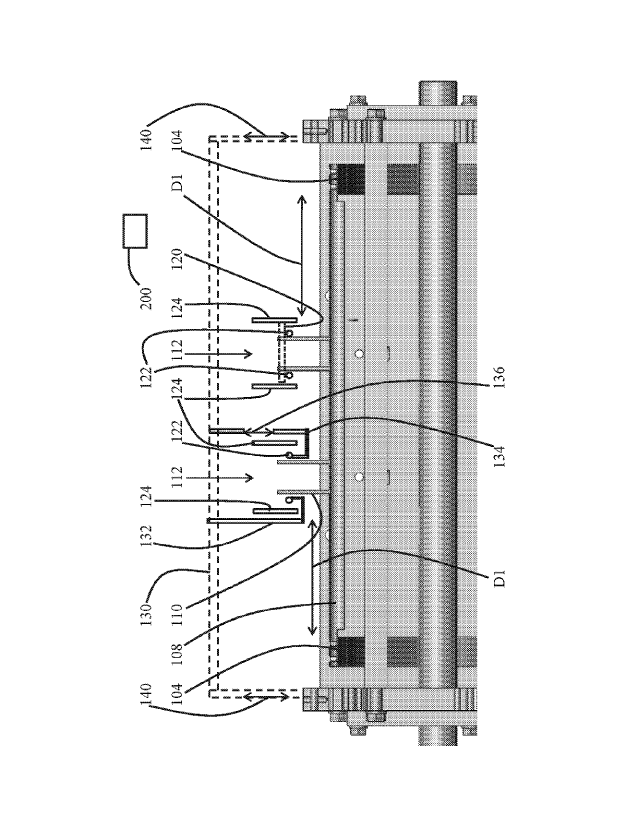
[0021] Referring to Figs. 3-6, a belt driven sandwiching machine
conveyor
arrangement 100 includes a support frame 102 and a pair of spaced apart belts
104 toward
the side rails 106 of the frame 102. A series of lateral pusher bars 108 are
connected to and
extend between the belts, with multiple pairs (here two pairs) of pusher pins
110 mounted
on each bar for moving wafers along respective wafer conveyance rows,
represented by
arrows 112. Notably, the positioning of the belts 104 toward the side rails
106 of the
machine frame results in the belts 104 being located outside of a central zone
where the
wafer conveyance rows 112 are located and therefore not beneath the locations
where
cream or other fillings are deposited (e.g., by overhead stencils represented
schematically
at 114) onto the traveling wafers. By way of example, the stencils 114 may
typically be
fed cream or other deposit material via a pump 115 from a source 117, and the
stencils may
3a
CA 2997678 2019-12-23
CA 02997678 2018-03-05
WO 2017/058742 PCT/US2016/053873
rotate as cream is output from outlet openings on the stencil that are aligned
with the rows
112 for depositing on passing wafers. The belts 104 may, for example, be
spaced laterally
from the conveyance path defined by the nearest wafer conveyance row 112 by a
distance
D1 of at least four inches (e.g., such as at least six inches or at least
eight inches), but other
variations are possible. A drive 119 for the belts is also shown in Fig. 4. A
downstream
arrangement may lay a second wafer atop the first after the filling is
deposited on the first
wafer.
[0022] The belts 104 may be synchronously driven and formed of a
polyurethane
belting with steel or Kevlar cord reinforcements. In one embodiment, each belt
may be an
Elatech (www.elatech.com) belt utilizing EMT (Elatech Mechanical Fastening)
technology.
The EMT technology utilizes no exposed metal parts, which reduces noise during
operation. EMT is straightforward to install and requires no field welds,
making in-field
service straightforward. In another embodiment, the belt may be an Elatech
belt utilizing
EFT (Elatech False Teeth) technology. The EFT technology is well-suited for
attachment
of cleats that cannot be welded onto polyurethane belts. The cleats can be
used for
mounting of the pusher bars and/or the ends of the pusher bars themselves may
be
configured as mountable cleats. This latter configuration is seen in Figs. 5
and 6 where the
end portions of the pusher bars 108 are undercut and include a set a fastener
openings for
mounting directly to the belt material. This arrangement enables individual
pusher bars to
be removed for cleaning, repair, replacement or machine modification without
removing
the belts or interfering with belt operation.
[0023] As indicated above, laterally extending pusher bars 108 extend
between the
spaced apart belts 104 (e.g., with one end of each bar connected to one belt
and the
opposite end of each bar connected to the other belt). Each bar 108 includes
upright pusher
pins 110 extending therefrom. A pair of pusher pins 110 is used in connection
with each
row 112 of wafer travel, where the wafers 120 (shown in dashed line form in
the right row
of Fig. 6) travel (e.g., by sliding) on a pair of guide wires 122 located
between two side
guides plates 124. The side guide plates 124 prevent lateral movement of the
wafers out of
the conveyance path of the row 112.
[0024] In order to adequately support the guide wires 122 and avoid any
interference with the moving lateral pusher bars 108, each guide wire may, for
example, be
connected with an overhead support frame member or structure 130 (here
represented by a
dashed line) that is mounted across the top of the frame. For example, in one
4
CA 02997678 2018-03-05
WO 2017/058742 PCT/US2016/053873
implementation shown on the left side of the left row 112 in Fig. 6 guide wire
supports 132
of fixed height dimension may be placed at spaced apart locations along the
length of the
row and connected with the overhead structure 130. Here, the supports 132
extend
downward along and then laterally beneath the side guide plate 124 and then
upward to the
guide wire 122
[0025] On the other hand, in some implementations the ability to adjust the
height
of the guide wires 122 is desired. For this purpose, as shown on the right
side of the left
row 112 in Fig. 6, each wire 122 may have an associated support 134 with an
adjustment
mechanism 136 (e.g., in the form of any of a telescoping connection adjustable
by
threading or a linear actuator, a settable rack and pinion arrangement or
other suitable
adjustment means) that extends down alongside the nearest guide plate 124 of
the support
wire 122, under the guide plate 124 and then back up to the support wire 122.
This
arrangement assures that the wire supports and/or the adjustment system do not
extend
down into the path of the lateral pusher bars 108. Raising and lowering of the
adjustment
mechanism 136 is used to reposition the height of the wire 122. Multiple such
adjustment
members may be located along the length of each support wire to adjust the
height of the
support wire at various locations (e.g., particularly at locations where
filling is dispensed
from the stencil assemblies onto the wafers). In one example, the raising and
lowering may
be achieved by a manual system (e.g., manual rotation of a handle). In another
example,
the raising and lowering may be achieved by a powered system (e.g., via a
servomotor or
other prime mover, such as a linear actuator as mentioned above, under control
of a
controller 200 shown in Fig. 6). Alternatively, the overhead frame structure
130 itself
could be raised and lowered (per adjustment mechanisms represented by arrows
140)
where the fixed height dimension supports 132 are used.
[0026] Eliminating chain drives in the conveying arrangement of a
sandwiching
machine provides enhanced cleanability and quieter operation, while avoiding
the need for
lubrication. The belts may be produced of an FDA approved material suitable
for food
environments. Locating the belts to the sides of the wafer conveyance rows and
filling
deposit areas reduces material build-up on the belts.
[0027] It is to be clearly understood that the above description is
intended by way
of illustration and example only, is not intended to be taken by way of
limitation, and that
other changes and modifications are possible. For example, while a machine
utilizing two
wafer conveying rows is shown, machines with only one or machines with more
than two
CA 02997678 2018-03-05
WO 2017/058742
PCT/US2016/053873
are contemplated. Moreover, the number of stencil die assemblies positioned
along the
length of the conveying arrangement can vary depending upon the particular
food product
being produced and number of wafer conveying rows.
6