Note: Descriptions are shown in the official language in which they were submitted.
CA 02998713 2018-03-14
WO 2017/046306
PCT/EP2016/071938
- 1 -
Method for guiding a machining head along a track to be
machined
The invention relates to a method for guiding a
machining head, in particular a laser machining head,
along a track to be machined, in particular along a
joint or a butt joint between two parts to be joined
that are to be welded to one another.
When welding with laser radiation, the laser beam must
be directed such that its focus, forming the machining
point, impinges exactly on the joint or the butt joint
of the parts to be joined that are to be welded to one
another. Used for this purpose are seam tracking
systems, which with the aid of triangulation sensors
record the actual position of the seam or butt joint,
that is to say of the track to be machined. In the case
of these systems, the distance of a line of light
projected onto the workpiece before the point of
impingement of the laser beam from the point of
impingement of the laser beam and the rate of
advancement of the laser point of impingement, that is
to say the machining point, are prescribed as
parameters.
A disadvantage of this procedure is that, especially in
the case of kinematic systems, in which the rate of
advancement changes during the welding operation, which
is the case in particular with robot-guided laser
machining heads, the actual position deviates from the
setpoint position of the laser point of impingement.
The reason for this is that the time, calculated from
the rate of advancement and the distance, for the
tracking of the laser point of impingement, that is to
say of the machining point generated by the laser beam,
is incorrectly calculated if the rate of advancement is
changed. Especially in the case of small diameters in
CA 02998713 2018-03-14
4
WO 2017/046306
PCT/EP2016/071936
- 2 -
the laser beam focus, the accuracy with which the laser
beam impinges on the track to be machined, that is to
say the joint or the butt joint, is a relevant variable
for the attachment cross section and consequently for
the quality of the welded connection. The smaller the
laser beam diameter, the more exactly the laser beam
must impinge on the joint.
Furthermore, errors may arise as a result of the
distance from the workpiece surface to the focal
position changing. As a result, the distance of a line
of light projected onto the workpiece from the point of
impingement of the laser on the workpiece surface also
changes. In order in the case of this error to shift
the focus of the laser beam back to the workpiece
surface, the distance of a beam-shaping optical unit
from the workpiece surface may be corrected. For this
purpose, for example, the beam-shaping optical unit in
the laser machining head may be adjusted. It is however
also possible in principle to adjust the laser
machining head perpendicularly with respect to the
workpiece surface.
DE 10 2010 060 162 53 discloses a method for increasing
the accuracy of the guidance of the machining laser of
joining devices by the light section or triangulation
method, in which the distance of a measuring line of
light ahead of a point of impingement of a machining
laser from the point of impingement is varied in the
longitudinal direction of the seam, in order to
determine from the image data thereby obtained the
topology of the workpiece with the aid of the light
section method. On the basis of the knowledge of the
topology of the workpiece, it is possible to compensate
for an error of the distance between the measuring line
of light and the laser machining point that is caused
by a change in height.
=
CA 02998713 2018-03-14
WO 2017/046306
PCT/EP2016/071938
- 3 -
DE 10 2006 004 919 Al discloses a further method for
guiding a laser machining head along a seam to be
welded by means of a light section method in which, in
advance in the welding direction, a laser line is
projected onto the seam to be welded and is measured by
an image processing unit. From the image of the laser
line, the profile of the seam to be welded is
determined, and consequently its actual position. The
measured deviation of the current position of the seam
to be welded from a setpoint position is taken as a
basis for determining a correction signal, which is
used directly, without taking into account the distance
of the measuring position from the welding position,
that is to say from the machining point, to guide the
laser focus determining the welding position along the
seam to be welded.
DE 10 2006 030 130 B3 discloses an adaptive laser
machining head which is provided with one or more
optical sensors for measuring the distance of the laser
machining head from the workpiece and for measuring the
velocity vector of the laser machining point in the
plane perpendicular to the direction of the distance,
that is to say in the plane corresponding to the
surface of the workpiece. On account of the optical
sensors used and the processing of the measurement data
determined, it is possible to guide the laser machining
point along a track to be machined. In this case it is
possible to carry out closed-loop control on the basis
of the rate of advancement of the laser machining point
in dependence on the distance of the working point from
the workpiece surface and/or on the direction in which
the laser beam is beamed in.
DE 10 2009 057 209 discloses a further laser machining
head, which is equipped with a scanner optical unit for
the working laser beam, with the aid of which, in
addition to seam guidance, the machining speed, that is
CA 02998713 2018-03-14
WO 2017/046306
PCT/EP2016/071938
- 4 -
to say the speed with which the laser machining point
is moved in relation to the workpiece, can be reduced
or increased in relation to the guiding speed, that is
to say in relation to the speed of the laser machining
head. The seam tracking itself, that is to say the
guidance of the laser machining point along the seam or
track to be machined, takes place once again on the
basis of the light section principle by means of
triangulation.
DE 10 2010 011 253 Al discloses a further method for
guiding a laser machining head along a track to be
machined in which the position of a seam or track to be
joined is recorded on the basis of the light section
principle with the aid of a line of light projected
onto the machining line ahead of the machining point.
Since, for an optimum joining process, the machining
point, that is to say the focus of the working laser
beam, Is intended always to run at a predetermined
height along the seam to be joined, the distance of the
line of light from the point of impingement of the
laser beam is also evaluated. In dependence on the
recorded distance, the laser machining head is moved up
and down perpendicularly with respect to the surface of
a workpiece to be machined, in order to keep the
distance of the line of light from the machining point
constant, whereby the distance between the laser
machining head and the workpiece, and consequently the
position of the focus of the working laser beam in
relation to the workpiece, is also kept constant.
Against this background, the invention is based on the
object of providing a further method for guiding a
machining head, in particular a laser machining head,
along a track to be machined with which the machining
point, that is to say In particular the focus of a
machining laser beam, is guided precisely along the
- 5 -
track to be machined, that is to say along a seam or
joint to be joined.
This object is achieved by a method as described
herein. Advantageous refinements and developments of
the invention are also described herein.
According to the invention, the machining point is not
set in the standard way after a prescribed delay time
after the recording of the position of a track to this
position, but instead the delay time is in each case
determined individually during the machining for each
machining point or for a successive group of machining
points from the respective actual machining speed and
the respective actual distance of a light section line
from the machining center point (TCP, Tool Center
Point). This achieves the effect that the adjustment of
the machining point always takes place exactly at the
time at which the machining point is at the location of
the track to the position of which the machining point
is to be set. This allows setting inaccuracies that
could considerably impair the quality of the machining
to be ruled out almost completely.
In an aspect, there is provided a method for guiding a
machining head along a track to be machined, in which
- a line of light is projected onto the track to be
machined, transversely with respect to the track, at
a distance in front of the machining point in the
machining direction,
- the distance between the line of light and the
machining point, and a position of the track in front
of the machining point are determined from images of
the line of light recorded continuously during the
machining, and
Date Recue/Date Received 2021-03-11
- 5a -
- the machining point is aligned with the track as
soon as the machining point reaches a respective
point on the track for which the position of the
track was determined,
wherein a machining speed at which the machining
point is guided along the track to be machined is
changing over time,
wherein a current machining speed at which the
machining point is guided along the track to be
machined is read from a control unit controlling the
movement of the machining head and is used as a
current parameter for calculating a time for tracking
of the machining point, and
wherein the time for the tracking of the machining
point at which the machining point reaches the
respective point of the track is determined from the
distance of the line of light from the machining
point and the current machining speed.
Although it is possible in principle to measure the
current machining speed, that is to say the actual
machining speed, by means of suitable methods, it is
provided according to the invention that the current
machining speed is read from a control unit controlling
the movement of the machining head and used as a
current parameter for the calculation of the time for
the tracking of the machining point.
In the case of an advantageous refinement of the
invention, it is also provided that the actual distance
between the line of light on the workpiece and the
machining point in the machining direction is recorded
and used as a current parameter for the calculation of
Date Recue/Date Received 2021-03-11
CA 02998713 2018-03-14
WO 2017/046306
PCT/EP2016/071938
- 6 -
the time for the tracking of the machining point. As a
result, the precision of the tracking of the machining
point is improved further.
Since it is necessary when machining a workpiece by
means of laser radiation, in particular when welding,
always to keep the focus of a machining laser beam at
the same distance from a workpiece surface, it is
provided in the case of an advantageous refinement of
the invention that the recorded actual distance between
the line of light and the machining point is used as a
parameter of a closed-loop control of the distance of
the focus of a machining laser beam from a workpiece
surface.
The closed-loop control of the distance of the focus of
the machining laser beam can in this case take place
either by displacement of the entire laser machining
head or by displacement of a beam-shaping optical unit
within the laser machining head.
The invention is explained in more detail below for
example on the basis of the drawing, in which:
Figure 1 shows a simplified schematic block diagram of
a machining head, in particular a laser machining head,
with a seam tracking system,
Figure 2 (a) shows a schematic representation of a
camera image of a workpiece surface in the region of a
laser point of impingement and a light section line,
and
Figure 2 (b) shows a schematic simplified sectional
representation of a workpiece transversely with respect
to the machining track with a machining laser beam and
fans of light for generating the light section line.
CA 02998713 2018-03-14
WO 2017/046306
PCT/EP2016/071938
- 7 -
In the various figures of the drawing, elements that
correspond to one another are provided with the same
designations.
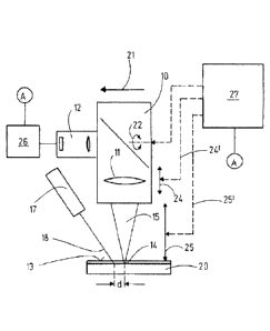
Figure 1 shows in a greatly simplified form a machining
head, in particular a laser machining head 10, with a
beam-shaping optical unit 11 and a camera 12 for
observing a workpiece surface 13 in the region of a
point of impingement 14 of a machining laser beam 15,
also referred to hereinafter simply as laser beam 15,
and a light line 16, which is projected from a light
section projector 17 by means of a fan of light 18 onto
the surface 19 of a workpiece 20.
The laser machining head 10 is guided by a machine
control, which is not represented any more
specifically, in the direction of advancement 21 at a
speed corresponding to the machining process. As
indicated by the double-headed arrow 22, the laser
machining head 10 can be pivoted or else displaced
laterally, in order to keep the point of impingement 14
of the laser beam 15 exactly on the track 23 to be
machined, that is to say on the butt joint between two
parts of a workpiece. Furthermore, the machine control
serves for adjusting the beam-shaping optical unit 11,
in particular the focusing optical unit within the
laser machining head 10, as is indicated by the double-
headed arrow 24. Furthermore, the entire laser
machining head 10 can also be adjusted according to the
double-headed arrow 25 perpendicularly with respect to
the workpiece surface 19, in order to set the height
position of the laser focus in relation to the
workpiece 20.
From the image data recorded by the camera 12, an image
processing unit 26 determines a distance d between the
light line 16 and the point of impingement 14 of the
laser beam 15 and also the position of the point of
CA 02998713 2018-03-14
WO 2017/046306
PCT/EP2016/071938
- 8 -
intersection Pn between the light line 16 and the butt
joint or track 23 in the y direction, that is to say in
the direction transverse to the direction of
advancement of the laser machining point 10, that is to
say transverse to an x direction.
To guide the point of impingement 14 of the machining
laser beam 15 precisely on the track 23 to be machined,
that is to say on the recorded butt joint, it is
necessary to determine the time after which the point
of impingement 14 of the laser beam 15 is set to the
recorded position of the track.
This time is calculated as the quotient of the distance
d divided by the current rate of advancement or
machining speed.
Although it is possible in principle to measure the
current rate of advancement, it is expedient if a
calculating unit 27, which is fed not only the position
y(Pn) determined from the camera image but also the
distance d between the point of impingement 14 of the
laser beam 15 and the light line 16, reads the current
machining speed from a control unit of the machine
control.
The distance d between the light line 16 and the point
of impingement 14 of the laser beam 15, determined by
the image processing unit 26, is used not only as a
parameter for calculating the time difference between
recording the position y(Pn) of the track and the
tracking of the point of impingement 14 of the laser
beam 15, but also as a parameter for setting the height
of the laser beam focus in relation to the surface 13
of the workpiece 20. By means of triangulation, it is
possible to determine from the comparison of the actual
distance with a setpoint distance the position of the
laser beam focus in relation to the workpiece surface
CA 02998713 2018-03-14
WO 2017/046306
PCT/EP2016/071938
-9--
13 in the z direction, that is to say perpendicular to
the workpiece surface 13. If the actual distance d is
less than the setpoint distance, the working laser
focus, which corresponds to the laser machining point,
that is to say the TCP, is located at a distance above
the workpiece surface 13. Conversely, if the actual
distance is greater than the setpoint distance, the
laser beam focus lies below the workpiece surface 13.
To move the laser beam focus into the desired position
perpendicularly with respect to the workpiece surface,
it is on the one hand possible to output a
corresponding actuating signal to the machine control,
which adjusts the entire laser machining head 10 in a
way corresponding to the double-headed arrow 25, as
indicated by the dashed line 25'. However, the laser
beam focus can also be adjusted by displacing or
changing the beam-shaping optical unit 11 in response
to a corresponding actuating signal, as indicated by
the dashed line 24'.
To ensure the quality of a laser machining, in
particular a welding process, precise seam tracking is
required. For this purpose, according to the invention
the actual rate of advancement during the machining
process, that is to say in particular during the
welding process, is read from the machine control and
used by the software of a calculating unit 27 as a
current parameter for the calculation of the time for
the tracking of the laser point of impingement 14. On
the basis of triangulation, the displacement of the
laser beam focus in the radiating direction (z
direction) is calculated from the change in the
distance of the light line 16 from the laser point of
Impingement 14, that is to say from the change in the
distance of the light section to the TCP, likewise
determined by the image processing unit 26. This value
is then used to displace the focusing or collimating
=
CA 02998713 2018-03-14
WO 2017/046306
PCT/EP2016/071938
- 10 -
lens in such a way that the laser beam focus again lies
on the workpiece surface 13.
To obtain precise seam tracking, therefore, according
to the invention both the rate of advancement, changing
over time, of the laser machining head in relation to
the workpiece and the changes of the distance of a
light section line from the machining center point,
that is to say from the laser point of impingement, are
taken into account. Both values are computationally
taken into account in the focus tracking for the
lateral seam tracking of the machining line.