Note: Descriptions are shown in the official language in which they were submitted.
SOLUTION CATHODE GLOW DISCHARGE ELEMENTAL ANALYSIS
[0001] (This paragraph is intentionally left blank.)
FIELD
[0002] The present disclosure relates generally to elemental analysis of
soluble
species in aqueous solutions. More particularly, the present disclosure
relates to elemental
analysis of samples based on solution cathode glow discharge technology
(SCGD).
BACKGROUND
[0003] Industrial processes requiring production of steam or other high
temperature
process fluids are subject to equipment fouling and scale formation issues. An
example of
one such process is the production of high-quality steam for SAGD (steam
assisted gravity
drainage) in the recovery of bitumen. The affected equipment may include, for
example,
water treatment operations, steam boilers, and once through steam generators
(OTSG).
[0004] Deposition and scaling at heat exchange surfaces occurs because
temperature, concentration, and pressure changes disrupt solubility equilibria
to cause solids
formation. Deposited substances are largely combinations of inorganic cations
and inorganic
and organic anions. The primary cations for scale formation are ions of Ca,
Mg, Fe, and Mn.
These cationic species combine with anionic species including SiO2, C032-, Cl-
, and organic
acids (humic and naphthalenic). Other elements that may contribute to fouling
are Cu, Al, Na,
Ba, Sr, K, Rb, Cs, and Li. Boiler fouling and scale formation may lead to
significant costs due
to losses in steam production efficiency and costly down-time. In spite of the
importance of
dissolved inorganic ions to boiler integrity, there is currently no on-line
means of monitoring
these metal ions at relevant concentrations for real-time process control.
[0005] Simultaneous multi-element analysis of metal ions is normally
performed by lab-
based techniques, such as inductively coupled plasma atomic emission
spectrometry (ICP-
AES). ICP-AES has never been adapted to on-line measurements because of high
argon gas
consumption and the requirement of frequent recalibrations due to instrument
drift. However, a
novel plasma spectrochemical technique has been described that does not
consume inert gas
and avoids instrument drift issues that plague traditional techniques. This
technique is called
-1-
Date recue/date received 2021-10-19
CA 02998750 2018-03-15
WO 2017/049410 PCT/CA2016/051121
solution cathode glow discharge (SCGD) and has shown linear calibration with
detection limits
in the low parts per billion range (see: Greda, K., etal., Comparison of
performance of direct
current atmospheric pressure glow microdischarges operated between a small
sized flowing
liquid cathode and a miniature argon or helium flow microjets, J. Anal. At.
Spectrom., 28, 1233-
1241 (2013) and Doroski, TA., etal., Solution-cathode glow discharge - optical
emission
spectrometry of a new design and using a compact spectrograph. J. Anal. At.
Spectrom., 2013.
28: p. 1090-1095). SCGD appears to be an ideal technique for simultaneous
multi-element
analysis of metal ions in on-line applications.
[0006] From the academic literature, a representation of the solution
cathode glow
discharge is shown in Figure 1. This design has superior analytical
performance and simplicity
compared to previous published versions. The glass capillary extends 3 mm
above the
grounded graphite rod and the tungsten anode is 3 mm above the glass
capillary. Electrical
contact between the tip of the glass capillary and the graphite rod is made
along the 3 mm
vertical glass capillary by the liquid overflow of the solution cathode.
Optimized electrical
contact between the tip of the glass capillary and the graphite rod is made
when the distance
that the glass capillary extends above the graphite is minimized. However,
distances less than
3 mm promote a glow-to-arc transition where the plasma anchors to the graphite
rod as
opposed to the tip of the glass capillary. Electrical arcing can destroy
electrode components and
prohibits the analytical performance of the instrument. Therefore, a
compromised distance of 3
mm is used and 2.0 mL/min is the lowest sample flow rate that can be used
before analytical
performance degrades (see: Wang, Z., et al., Design modifications of a
solution cathode glow
discharge atomic emission spectrometer for the determination of trace metals
in titanium
dioxide. J. Anal. At. Spectrom., 2014. 00: p. 1-9 and Zhang, Z., etal.,
Determination of trace
heavy metals in environmental and biological samples by solution cathode glow
discharge
atomic emission spectrometry and addition of ionic surfactants for improved
sensitivity. Talanta,
2014. 119: p. 613-619). Lower flow rates degrade the analytical performance
since the electrical
connection through the fluid along the 3 mm glass capillary is degraded as
flow rates decrease.
[0007] Within the patent literature, several variations of SCGD devices are
disclosed.
One of the earlier patents describing a SCGD device is United States patent
No. 5,760,897 from
Cserfalvi et al.; however, the inventors do not provide a proposed flow rate.
Later patent
application published WO/2007/012904, also from Cserfalvi et al. discloses a
continuous flow
rate of approximately 5-10 mL/min. China patent application CN 103163116
discloses the
lowest flow rate achieved as 2.5 mL/min. United States patent US 7,929,138 to
Webb etal.
discloses an SCGD configuration that facilitates analysis at low sample
solution flow rates
ranging from 2.0 to 3.0 mL/min. Although the inventors note that lower flow
rates such as 1.5
-2-
CA 02998750 2018-03-15
WO 2017/049410 PCT/CA2016/051121
mL/min. are also supported by the system, they disclose that their present
method enables
analysis between 2.0 and 2.5 mL/min. The flow rates in the Webb system are
limited by the
distance between the base of the plasma and the overflow solution in the
reservoir in contact
with the grounding electrode, which creates a greater resistance. There is
therefore a need for
an SCGD apparatus capable of flow rates below 2.0 mL/min that maintains a
stable plasma
emission and does not degrade the analytical performance.
[0008] To initiate the plasma in an SCGD device, a spark is required to
jump the gap
between the anode and flowing solution cathode and in the past this has been
accomplished by
one of two methods. Currently, the most common method is to physically lower
the anode until
it is within 1 mm of the cathode and then apply power from the de power
supply. At less than 1
mm distance, common dc power supplies have a sufficient voltage limit to jump
the gap and
initiate the plasma. Once the plasma is lit, the anode can be retracted to
leave a 3 mm gap
between electrodes. Thus, this method requires a mechanical mechanism to move
the anode
up and down, which has potential for wear and breakage. If the anode could be
fixed in position,
a simpler and more robust anode/cathode configuration can be built. Another
method to initiate
the plasma is to add a second high voltage power supply where the voltage, in
excess of 10,000
V, is used solely to initiate the plasma by jumping the 3 mm gap between
electrodes. This
method runs the risk of damaging the main power supply that drives the plasma.
There is
therefore a need in the art for a method of initiating the plasma in SCGD that
allows for a fixed
configuration of the anode and cathode and does not require a second power
supply.
[0009] To date, SCGD devices have primarily been used for the analysis of
metal ions in
aqueous solutions. Molecular emissions have been seen as background but SCGD
devices
have not been previously used for analysis of molecular species. Oxides,
nitrides, and hybrids
are classes of molecular species that can be formed in atmospheric pressure
plasmas and can
potentially be detected by molecular emission.
[0010] Isotopic analysis is an essential technique in the fields of
medicine, chemistry,
materials science, archeology, hydrology, carbon dating, and nuclear
forensics. Traditionally,
isotopic information has been determined by sophisticated isotope ratio mass
spectrometers.
Recently, laser ablation molecular isotopic spectrometer (LAM IS) has been
used to provide
isotopic analysis based on optical emission of molecular species. LAM IS has
been shown to
measure isotopes of hydrogen, boron, carbon, nitrogen, oxygen and chlorine
(see: Bol'shakov,
A.A., et al., Laser ablation molecular isotopic spectrometry for rare isotopes
of the light
elements. Spectroscopy, 2014. 29(6): p. 30-39). Although SCGD has not been
previously
disclosed for isotope measurement, isotopic analysis can be more practically
accomplished
using molecular spectra since the difference in isotopic masses has only a
small effect on the
-3-
CA 02998750 2018-03-15
WO 2017/049410 PCT/CA2016/051121
electronic transitions in atoms, but a relatively large effect on the
vibrational and rotational
energy levels in molecules.
[0011] It is, therefore, desirable to provide improved apparatus and
methods for SCGD.
SUMMARY
[0012] It is an object of the present disclosure to obviate or mitigate at
least one
disadvantage of previous apparatus and methods for SCGD.
[0013] The present disclosure provides a modified solution cathode glow
discharge
(SCGD) apparatus and methods to achieve stable plasmas at low sample flow
rates with
optimized emission for measurement of the elemental composition of dissolved
substances in
aqueous solutions by atomic emission spectrometry. The modified SCGD design
provides a
robust electrical connection to the plasma while reducing or preventing glow-
to-arc transitions.
As the solution sample flow rate decreases from 4.0 to 1.0 mL/min, the
emission intensity of
dissolved substances increases with a corresponding decrease in emission
noise.
[0014] In a first aspect, the present disclosure provides a solution
cathode glow
discharge (SCGD) apparatus including an anode adapted to connect to a de power
source, the
anode having an anode tip, a grounding electrode adapted to connect to the dc
power source,
the grounding electrode having a grounding electrode tip proximate the anode,
the region
proximate the grounding electrode tip and the anode tip forming a plasma
emission region, a
capillary tube adapted to receive a solution sample, the capillary tube having
an outlet tip
proximate the grounding electrode tip, and a solution-catching collar between
the outlet tip of
the capillary tube and a base of the grounding electrode tip, adapted to
maintain a solution level
proximate the plasma emission region.
[0015] In an embodiment disclosed, the solution-catching collar includes a
circular weir.
[0016] In an embodiment disclosed, the SCGD apparatus further includes a
circular
bubble blocker, proximate the outlet tip of the capillary tube to prevent
bubbles from directly
entering the plasma emission region.
[0017] In an embodiment disclosed, the solution-catching collar includes a
wicking
element.
[0018] In an embodiment disclosed, the wicking element includes a glass
frit wick or a
porous ceramic wick.
[0019] In an embodiment disclosed, the wick is disk shaped.
[0020] In an embodiment disclosed, the wick is tapered, having a wick tip
proximate the
grounding electrode tip.
-4-
CA 02998750 2018-03-15
WO 2017/049410 PCT/CA2016/051121
[0021] In an embodiment disclosed, the SCGD apparatus further includes an
annular
flow restrictor around the grounding electrode such that, in operation, a
region of the grounding
electrode is substantially covered by waste sample solution.
[0022] In an embodiment disclosed, the annular flow restrictor includes an
0-ring or a
secondary wicking element.
[0023] In an embodiment disclosed, the solution-catching collar is situated
between
about 0.3 and 3.0 mm below the outlet tip of the capillary tube.
[0024] In an embodiment disclosed, the anode and the grounding electrode
are fixed,
the distance between the anode tip and the grounding electrode tip set in
advance of operation.
[0025] In an embodiment disclosed, the SCGD apparatus further includes a
thermally
conductive copper heat sink thermally connected with the anode to dissipate
heat from the
anode.
[0026] In a further aspect, the present disclosure provides a method of
analyzing a
solution sample including: providing a solution cathode glow discharge (SCGD)
apparatus,
providing the solution sample to a capillary tube of the SCGD apparatus at a
sampling flow rate
less than 2.0 mL/min, initiating or maintaining a stable plasma glow discharge
by applying an
electrical current, and analyzing the glow discharge emission.
[0027] In an embodiment disclosed, the method is used with a SCGD apparatus
having
an anode adapted to connect to a de power source, the anode having an anode
tip, a grounding
electrode adapted to connect to the dc power source, the grounding electrode
having a
grounding electrode tip proximate the anode, the region proximate the
grounding electrode tip
and the anode tip forming a plasma emission region, a capillary tube adapted
to receive a
solution sample, the capillary tube having an outlet tip proximate the
grounding electrode tip,
and a solution-catching collar between the outlet tip of the capillary tube
and a base of the
grounding electrode tip, adapted to maintain a solution level proximate the
plasma emission
region.
[0028] In an embodiment disclosed, the method uses the SCGD apparatus
wherein the
solution-catching collar includes a circular weir.
[0029] In an embodiment disclosed, the method uses the SCGD apparatus
wherein the
solution-catching collar includes a wicking element.
[0030] In an embodiment disclosed, the method uses the SCGD apparatus
further
including an annular flow restrictor around the grounding electrode such that,
in operation, a
region of the grounding electrode is substantially covered by waste sample
solution.
[0031] In an embodiment disclosed, the sampling flow rate is about 1.5
mL/min.
-5-
CA 02998750 2018-03-15
WO 2017/049410 PCT/CA2016/051121
[0032] In an embodiment disclosed, the step of initiating the stable plasma
glow
discharge includes pulsing the solution sample at an initiation flow rate, the
initiation flow rate
greater than the sampling flow rate.
[0033] In an embodiment disclosed, the method further includes contacting
an anode of
the SCGD apparatus with the solution sample during the initiating.
[0034] In an embodiment disclosed, the method is conducted online or
continuous or in
a real-time environment.
[0035] In an embodiment disclosed, the step of analyzing the stable plasma
glow
discharge comprises applying a low pass filter to remove high frequency noise.
[0036] In an embodiment disclosed, the step of analyzing the stable plasma
glow
discharge emission comprises detecting one or more molecular species.
[0037] In an embodiment disclosed, the method further includes
differentiating isotopes
of the one or more molecular species.
[0038] In an embodiment disclosed, the one or more molecular species are
dissolved
silica or colloidal silica.
[0039] In a further aspect, the present disclosure provides a method of
measuring
colloidal counterions in an acidified solution sample containing clay, the
method including
providing a solution cathode glow discharge (SCGD) apparatus, providing an
unfiltered solution
sample to a capillary tube of the SCGD, initiating or maintaining a plasma
glow discharge by
applying an electrical current, and detecting at least the sodium glow
discharge from the
unfiltered solution sample, providing a filtered solution sample to the
capillary tube, the filtered
solution sample being substantially free from clay, initiating or maintaining
a plasma glow
discharge by applying an electrical current, and detecting at least the sodium
glow discharge
from the filtered solution sample, subtracting the sodium glow discharge of
the filtered solution
sample from the sodium glow discharge of the unfiltered solution sample to
indicate a measure
of clay counterions released by acidification.
[0040] In an embodiment disclosed, the net sodium glow discharge indicates
a relative
clay content of the solution sample.
[0041] In an embodiment disclosed, the method is used with a SCGD apparatus
having
an anode adapted to connect to a de power source, the anode having an anode
tip, a grounding
electrode adapted to connect to the de power source, the grounding electrode
having a
grounding electrode tip proximate the anode, the region proximate the
grounding electrode tip
and the anode tip forming a plasma emission region, a capillary tube adapted
to receive a
solution sample, the capillary tube having an outlet tip proximate the
grounding electrode tip,
and a solution-catching collar between the outlet tip of the capillary tube
and a base of the
-6-
CA 02998750 2018-03-15
WO 2017/049410 PCT/CA2016/051121
grounding electrode tip, adapted to maintain a solution level proximate the
plasma emission
region.
[0042] Other aspects and features of the present disclosure will become
apparent to
those ordinarily skilled in the art upon review of the following description
of specific
embodiments in conjunction with the accompanying figures.
BRIEF DESCRIPTION OF THE DRAWINGS
[0043] Embodiments of the present disclosure will now be described, by way
of example
only, with reference to the attached Figures.
[0044] Fig. 1 is a schematic of a prior art solution cathode glow discharge
(see: Doroski,
TA., etal.);
[0045] Fig. 2 is a schematic of a solution cathode glow discharge apparatus
of the
present disclosure, in a weir and bubble blocker embodiment;
[0046] Fig. 3 is a close up of the solution cathode glow discharge
apparatus of Fig. 2;
[0047] Fig. 4 are embodiments of a stainless steel weir (left) and a
stainless steel
bubble blocker (right), Swagelok part numbers SS-404-1 and SS-104-1
respectively of the
present disclosure;
[0048] Fig. 5 is a graph of emission stability of K and Rb at 10 mg/L as
measured with
Vorsd with sample flow rate;
[0049] Fig. 6 is a graph of emission intensity, indicating long term
stability of SCGD
emission source from 7.5 ppm Li, 1 s integration time, low pass digitally
filtered. Long term
stability of 0.6 % rsd between 1 and 3.3 hours. Short term stability of 0.05 %
rsd over 16
consecutive points;
[0050] Fig. 7 is a graph of normalized emission intensity, indicating the
effect of
emission intensity of K and Rb at 10 mg/L with sample flow rate;
[0051] Fig. 8 is a graph of current, indicating the effect of sample flow
rate on current
while operating the power supply in the constant voltage mode;
[0052] Fig. 9 is a graph of change in resistance, indicating a decrease in
electrical
resistance as the sample flow rate increases;
[0053] Fig. 10 is a schematic of a solution cathode glow discharge
apparatus of the
present disclosure, in a glass frit disk wicking element embodiment;
[0054] Fig. 11 is a schematic of a solution cathode glow discharge
apparatus of the
present disclosure, in a tapered porous ceramic wicking element embodiment;
[0055] Fig. 12 is a graph of current, indicating current measurements with
sample
solution flow rates of 1.0 - 4.0 mL/min taken with quartz capillary tube
lengths of 0.3 ¨ 3.0 mm
-7-
CA 02998750 2018-03-15
WO 2017/049410 PCT/CA2016/051121
above the wicking element. The tube length of 0.3 mm was with the tapered
porous ceramic
wick and all others were with the glass frit disk wick;
[0056] Fig. 13 is a graph of noise in the current measurements represented
as %rsd
with sample solution flow rates of 1.0 - 4.0 mlimin taken with quartz
capillary tube lengths of 0.3
¨ 3.0 mm above the wicking element. The tube length of 0.3 mm was with the
tapered porous
ceramic wick and all others were with the glass frit disk. Data collected at
1.67kHz, 10,000
points;
[0057] Fig. 14; is a graph of normalized cYorsd values for emission
intensity from Rb, K,
Ca, and Mg for flow rates ranging from 1.0 to 4.0 mUmin;
[0058] Fig. 15 is a graph of normalized emission intensity for Rb, K, Ca,
and Mg for
sample flow rates ranging from 1.0 to 4.0 mi./min;
[0059] Fig. 16 is an exemplary pump program to pulse the sample delivery to
initiate the
plasma;
[0060] Fig. 17 is an exemplary design criteria for a low pass digital
filter;
[0061] Fig. 18 is a graph of emission intensity for blank subtracted 10 ppm
Mg, 80 ms
integration, 32 scans averaged;
[0062] Fig. 19 is a graph of emission intensity for blank subtracted 10 ppm
Ca, 1000 ms
integration, 32 scans averaged;
[0063] Fig. 20 is a graph of emission intensity for blank subtracted 10 ppm
Cu, 230 ms
integration, 32 scans averaged;
[0064] Fig. 21 is a graph of emission intensity for blank subtracted 10 ppm
Al, 4550 ms
integration, 32 scans averaged;
[0065] Fig. 22 is a graph of emission intensity for blank subtracted 10 ppm
Fe, 4030 ms
integration, 32 scans averaged;
[0066] Fig. 23 is a graph of emission intensity for raw Na emission,
unknown
concentration, 90 ms integration, 32 scans averaged;
[0067] Fig. 24 is a graph of emission intensity for blank subtracted 10 ppm
Ba, 6.5 s
integration, 32 scans averaged;
[0068] Fig. 25 is a graph of emission intensity for blank subtracted 10 ppm
Sr, 2210 ms
integration, 32 scans averaged;
[0069] Fig. 26 is a graph of emission intensity for blank subtracted 10 ppm
K and Rb,
9.2 ms integration, 32 scans averaged;
[0070] Fig. 27 is a graph of emission intensity for blank subtracted 20 ppm
Cs, 65 ms
integration, 32 scans averaged;
-8-
CA 02998750 2018-03-15
WO 2017/049410 PCT/CA2016/051121
[0071] Fig. 28 is a graph of emission intensity for blank subtracted 10 ppm
Li, 6 ms
integration, 32 scans averaged;
[0072] Fig. 29 is a graph of emission intensity for blank subtracted
filtered SAGD
process water, diluted 10:1, 1.9 ms integration, 32 scans averaged;
[0073] Fig. 30 is a graph of emission intensity for blank subtracted
filtered SAGD
process water, diluted 10:1, 180 ms integration, 32 scans averaged;
[0074] Fig. 311s a graph of emission intensity for blank subtracted
filtered SAGD
process water, diluted 10:1, 6.5 s integration, 32 scans averaged;
[0075] Fig. 32 is a graph of emission intensity for blank subtracted
filtered SAGD
process water, diluted 10:1, 430 ms integration, 32 scans averaged;
[0076] Fig. 33 is a graph of emission intensity for steam assisted gravity
drainage
(SAGD) produced water solution diluted 10:1 spiked with 10 ppm Cs, 130 ms
integration, blank
subtracted, 32 scans averaged;
[0077] Fig. 34 is a graph of emission intensity for SAGD produced water
solution diluted
10:1 spiked with 10 ppm Li, 5.7 ms integration, blank subtracted, 32 scans
averaged;
[0078] Fig. 35 is a graph of emission intensity for SAGD produced water
solution diluted
10:1 spiked with 10 ppm Rb, 9.2 ms integration, blank subtracted, 32 scans
averaged;
[0079] Fig. 36 is a graph of emission intensity for SAGD produced water
solution diluted
10:1 spiked with 10 ppm Ba, 6.5 s integration, blank subtracted, 32 scans
averaged;
[0080] Fig. 37 is a graph of emission intensity for SAGD produced water
solution diluted
10:1 spiked with 10 ppm Sr, 3315 ms integration, blank subtracted, 32 scans
averaged;
[0081] Fig. 38 is a graph of emission intensity for SAGD produced water
solution diluted
10:1 spiked with 10 ppm Ca, 1430 ms integration, blank subtracted, 32 scans
averaged;
[0082] Fig. 39 is a graph of emission intensity for SAGD produced water
solution diluted
10:1 spiked with 10 ppm Cu, 170 ms integration time, blank subtracted, 32
scans averaged;
[0083] Fig. 40 is a graph of emission intensity for SAGD produced water
solution diluted
10:1 spiked with 10 ppm Mg, 150 ms integration time, blank subtracted, 32
scans averaged;
[0084] Fig. 41 is a graph of emission intensity for SAGD produced water
solution diluted
10:1 spiked with 10 ppm Fe, 4095 ms integration, blank subtracted, 32 scans
averaged;
[0085] Fig. 42 is a graph of emission intensity for SAGD produced water
solution diluted
10:1 spiked with 10 ppm Al, 3640 ms integration, blank subtracted, 32 scans
averaged;
[0086] Fig. 43 is a graph of emission intensity for SAGD produced water
solution, diluted
100:1, filtered emission subtracted from unfiltered emission, acquired with an
Ocean Optics
SD2000;
-9-
CA 02998750 2018-03-15
WO 2017/049410 PCT/CA2016/051121
[0087] Fig. 44 is a graph of emission intensity for SiO vibrational band
emission from
248.7 nm, 241.4 nm, 238.6 nm, 236.7 nm, 234.5 nm, and 229.8 nm from the SCGD
plasma
emission source;
[0088] Fig. 45 is a graph of emission intensity for SAGD produced water
diluted 10:1
spiked with silica, 6.5 s integration, blank subtracted, 32 scans averaged,
low pass digitally
filtered;
[0089] Fig. 46 is a graph of emission intensity for standard addition
determination of
silica in unfiltered SAGD produced water, signal defined at the emission
intensity difference
between 248.85 nm and 248.45 nm;
[0090] Fig.47 is a graph of normalized emission spectra of 160H and 160D by
the SCGD
technique, 32 scans averaged;
[0091] Fig. 48 is a graph of normalized emission spectra of the entire 160H
and 160D
band head by SCGD;
[0092] Fig. 49 is a graph of normalized emission spectra of 160H and 1600
between 306
and 310 nm by SCGD;
[0093] Fig. 50 is a schematic of a grounding electrode of a solution
cathode glow
discharge apparatus of the present disclosure, in a wicking element and a
secondary element
configuration; and
[0094] Fig. 511s a schematic of a grounding electrode of a solution cathode
glow
discharge apparatus of the present disclosure, in a flush wicking element
configuration.
DETAILED DESCRIPTION
[0095] Generally, the present disclosure provides a method and system for
solution
cathode glow discharge elemental analysis.
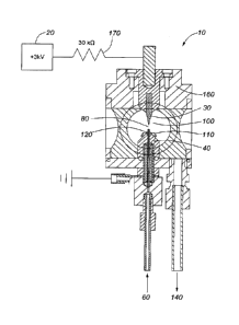
[0096] Referring to Figure 1, a representation of a solution cathode glow
discharge
(SCGD) emission cell 10 found in the prior art is shown. A dc power source 20
connects to an
anode 30 and a grounding electrode 40. The anode 30 may be, for example, a
tungsten anode
rod. The grounding electrode 40 may be, for example, a grounded graphite
cathode rod. A
capillary tube 50 delivers a solution sample 60 from a pump (not shown)
proximate a top 70 of
the grounding electrode 40. A plasma emission region 80 remains between an
outlet tip 90 of
the capillary tube 50 and a tip 100 of the anode 30. The capillary tube 50 may
be, for example,
a glass capillary tube. Upon activation of the power source 20, a plasma is
formed in the plasma
emission region 80.
[0097] The capillary tube 50 extends 3 mm above the top 70 of the grounding
electrode
40, and the tip 100 of the anode 30 is 3 mm above the outlet tip 90 of the
capillary tube 50.
-10-
CA 02998750 2018-03-15
WO 2017/049410 PCT/CA2016/051121
Electrical contact between the outlet tip 90 of the capillary tube 50 and the
grounding electrode
40 is made along the 3 mm vertical capillary tube 50 by the overflow of the
solution sample 60
from the outlet tip 90 of the capillary tube 50. Optimized electrical contact
between the outlet tip
90 of the capillary tube 50 and the grounding electrode 40 is made when the
distance that the
capillary tube 50 extends above the grounding electrode 40 is minimized.
However, distances
less than 3 mm tend to promote a glow-to-arc transition where the plasma
anchors to the
grounding electrode 40 as opposed to the outlet tip 90 of the capillary tube
50. Electrical arcing
can destroy electrode components and prohibits the analytical performance of
the SCGD
instrument. Therefore, typically a compromised distance of about 3 mm is used
and 2.0 nriUrnin
is the lowest flow rate for the solution sample 60 that can be used before
analytical performance
degrades.
[0098] Three different electrical resistance values are shown for a SCGD
device found
in the prior art. R1 is the ballast resistor 170 used to increase the output
impedance of the de
power source 20 and limit the current delivered. R2 is the gas phase
resistance of the plasma
and R3 is the resistance of the electrical connection between the base of the
plasma and the
grounding electrode 40. This electrical connection is made through the
overflow of acidified
solution sample 60.
[0099] The incorporation of a solution-catching collar in the presently
disclosed
apparatus and methods significantly improves the operating characteristics of
the solution
cathode glow discharge (SCGD) emission cell found in the prior art. Reduction
of R3 has been
achieved by the insertion of a solution-catching collar in the form of a weir
110 (see Figs. 2-4) or
a wicking element 180 (see Figs. 10-11, 50-51) between the tip 90 of the
capillary tube 50 and
the grounding electrode 40. The resistance of any material is directly
proportional to its length
and inversely proportional to its cross-sectional area. Therefore, placing a
weir (110) or a
wicking element 180 between the tip of the capillary tube 50 and the grounding
electrode 40
increases the cross-sectional area of R3 and reduces the value of R3.
[00100] Solution-Catching Collar: Weir and Bubble Blocker Embodiment
[00101] Referring to Figures 2-4, an embodiment of the SCGD emission cell
10 is shown.
In an embodiment disclosed, the solution-catching collar is provided in the
form of a weir 110. In
an embodiment disclosed, the weir 110 is stainless steel. In an embodiment
disclosed a bubble
blocker 120 is also provided. In an embodiment disclosed, the bubble blocker
120 is stainless
steel.
[00102] The weir 110 is placed within a low surface tension region of waste
solution
sample 140. The waste solution sample 140 has a sheeting action within this
region and
substantially uniformly spills over an upper side 150 of the weir 110, keeping
the level of the
-11-
CA 02998750 2018-03-15
WO 2017/049410 PCT/CA2016/051121
solution sample 60 constant with respect to the outlet tip 90 of the capillary
tube 50. In an
embodiment disclosed, the capillary tube 50 is made of quartz, which is an
inert material and
has a higher melting point than glass. In alternative embodiments, the
capillary tube 50 can be
carbon nanotubes or graphite.
[00103] In an embodiment disclosed, the weir 110 raises the level of the
solution sample
60 to within approximately 1.5 mm of the outlet tip 90 of the capillary tube
50. Raising this level
has the effect of reducing the electrical resistance between the outlet tip 90
of the quartz
capillary tube 50 and the grounding electrode 40. Electrical measurements were
made in a
constant voltage mode with and without the weir 110 and the bubble blocker
120. At the same
applied voltage, the current was 65 mA without the weir 110 and the bubble
blocker 120 and 74
mA with the weir 110 and the bubble blocker 120. This represents a reduction
in electrical
resistance of 3776 0 when the weir 110 and the bubble blocker 120 are in
place. The weir 110
and the bubble blocker 120 are simply placed on top of the grounding electrode
40 as shown in
Figures 2 and 3. The weir 110 leaves a thin layer of solution sample 60
covering the top of the
grounding electrode 40 and the bubble blocker 120. This solution sample
covering removes any
electrical "hot spots" where a glow-to-arc transition can be initiated if the
solution sample layer
were absent. In an embodiment disclosed the height of the weir 110 may be
increased, and in
an embodiment disclosed the weir 110 is raised towards the outlet tip 90 of
the quartz capillary
tube 50.
[00104] In an embodiment disclosed, the anode 30 is made from a 1/8"
tungsten carbide
welding electrode ground to a point at the tip 100 with a 20 degree angle.
Thermal management
of the tungsten carbide anode 30 is achieved by placing the base of the anode
30 into thermally
conductive copper heat sink 160. This prevents the anode 30 from overheating
and has been
shown to improve plasma stability (see: United States Patent No. 4,156,828,
Maisenhalder et
al., Glow Discharge Apparatus And A Method Of Operating Same, 1979). The
grounding
electrode 40 was made from copper and was passivated by coatings of
electroless nickel and
gold. The output impedance of the dc power source 20 was increased with the
use of ballast
resistors 170. The ballast resistors were a series connection of up to six 5k0
wire wound power
resistors for a maximum ballast resistance of 30k0. A maximum ballast
resistance of 30k0
would require a dc voltage of +3kV. Alternatively, at a ballast resistance of
15k0, a de voltage of
+2kV could be used. Each resistor was mounted on a high efficiency heat-pipe
heat sink with
forced-fan cooling to keep the resistor at ambient temperature preventing
drift. The glow-to-arc
transition is inhibited with the use of a ballast resistor. The plasma was
powered by a de power
supply, with appropriate supply of voltage and current, for example Glassman
model
PS/EWO3R200-115 with a stability of 0.01% per hour after 0.5 hour warm-up,
0.05% per 8
-12-
CA 02998750 2018-03-15
WO 2017/049410 PCT/CA2016/051121
hours. The plasma was created between the 3.0 mm gap between the capillary
tube 50 and the
tip 100 of the anode 30. For routine analytical work, the image of the plasma
will be focused
onto the entrance slit of a spectrometer (not shown). In an embodiment
disclosed, the quartz
capillary tube 50 delivering the flowing solution sample 60 to the plasma
emission region 80 has
an outside diameter of 1.0 mm, and an inside diameter of 0.5 mm. The flow of
the solution
sample 60 of between 1.0 to 3.5 mL/min was provided with a pulseless or pulse
dampening
pump, for example Valco Instruments model M50 pump (not shown). This pump can
control flow
from between 1 pL/min to 25 mL/min. The solution sample 60 is acidified prior
to entry into the
pump, for example in 0.1M HNO3. In alternative embodiments, the solution
sample 60 could be
prepared in hydrochloric acid, sulfuric acid, or another suitable acid. The
waste solution sample
140 was removed from the SCGD emission cell 10 by gravity drainage.
[00105] In operation a pump (not shown) supplies the sample solution 60 to
the outlet tip
90 via the capillary tube 50. The sample solution 60 flows over bubble blocker
120 and the
solution-catching collar in the form of the weir 110, down the side of the
grounding electrode 40
and the waste solution sample 140 disposed of. Upon application of the dc
power source 20,
plasma is generated in the plasma emission region 80 and the emissivity of the
plasma
analyzed.
[00106] Test Setup
[00107] Unless otherwise stated, stability of the SCGD was determined at a
flow rate of
1.5 mL/min and the solution sample 60 was made in 0.1M HNO3.
[00108] All spectral data was acquired with an Oriel 77200 0.25 m scanning
monochromator (unless otherwise stated), a 1200 line/mm grating was used for
all spectral
acquisitions greater than 589 nm and a 2400 line/mm grating for acquisitions
below 589 nm. A
Mightex TCE-1304-U CCD line camera was mounted at the exit focal plane of the
monochromator, using a Toshiba 3648 pixel CCD (TCD1304DG) with a pixel size of
8 x 200
pm.
[00109] Stability of Plasma Emission
[00110] Referring to Figure 5, the effect of the flow rate of the solution
sample 60 on
emission stability from dissolved K (250) and Rb (260) at 10 mg/L is shown.
Higher flow rates
result in a decrease in emission stability and stability is optimized at a
flow rate of 1.0 mL/min.
[00111] The long term percent relative standard deviation (%rsd) determined
over a
period of 2.3 hours with 4038 consecutive data acquisitions was calculated to
be 0.6% for Li.
The short term %rsd measured with 16 consecutive data acquisitions was
calculated to be
0.05% for Li. For comparative purposes, the short term %rsd of published
values for the SCGD
are 1-2 %rsd (see: Webb, M.R., etal., Compact glow discharge for the elemental
analysis of
-13-
CA 02998750 2018-03-15
WO 2017/049410 PCT/CA2016/051121
aqueous samples. Anal. Chem., 2007. 79: p. 7899-7905), 0.6-7 %rsd (see:
Doroski, TA., etal.),
and better than 5 %rsd (see: Greda, K. etal.) when the number of measurements
ranged only
from 5 to 10 over a time period of a few minutes at most. Also, the stability
data from this
current study compares very favorably to the lab-based technique of
inductively coupled plasma
atomic emission spectrometry (ICP-AES) where short term %rsd values can range
from 1-2%,
(see: Belchannber, R.M. and Horlick G., Correlation study of internal
standardization in
inductively coupled plasma atomic emission spectrometry. Spectrochimica Acta
Part B, 1982.
37(12): p. 1037-1046 and Broekaert, J.A., Analytical Atomic Spectrometry with
Flames and
Plasmas 2005, Verelag GmbH, Weinheim: Wiley-VCH) and are considered
satisfactory when
they are <1% (see: Todoli, J.-J. and Mermet, J.M., Liquid Sample Introduction
in ICP
Spectrometry 2008: Elsevier).
[00112] Emission Intensity
[00113] Referring to Figure 6, optical measurements of emission intensity
270 were made
with an Ocean Optics SD2000 covering the visible to near-IR portion of the
spectrum (grating
600 lines/mm, blazed at 500 nm, 25 um slit, OFLV-3, 2048 pixel CCD Sony
1LX511, 42 mm
focal length, resolution FWHM 1.4 nm). A 1.0 second integration time was used.
[00114] Sensitivity of Plasma Emission
[00115] Referring to Figure 7, the effect of the flow rate of the solution
sample 60 on
emission intensity from dissolved K (280) at 766.5 nm and Rb (290) at 780.0 nm
at 10 mg/L is
shown. Higher flow rates result in a decrease in emission intensity and
emission intensity is
optimized at a flow rate of about 1.0 mL/min.
[00116] Reduced Sample Flow Rates
[00117] Referring to Figures 8 and 9, the effect of the flow rate of the
solution sample 60
on current 300 and electrical resistance 310 is shown. These measurements were
taken with
the weir 110 and the bubble blocker 120 in place. It is clear that a higher
flow rate favors
improved electrical contact between the outlet tip 90 of the quartz capillary
tube 50 and the
grounding electrode 40. This occurs because a higher flow rate produces a
thicker conduit of
waste sample solution 140 and facilitates less resistance to current.
[00118] Optimized conditions will occur at low flow rates that promote
signal intensity and
stability. If flow rates are reduced too far, degradation of the electrical
contact between the
outlet tip 90 of the capillary tube 50 and the grounding electrode 40 will
occur.
[00119] In addition to higher emission intensity, reduced sample flow rates
are desirable
in terms of lower total sample and acid consumption. For example, for an
online industrial
process control application, the solution sample 60 will be diluted and
acidified prior to being
introduced into the SCGD. Acid, from an acid reservoir, would be added to and
mixed with the
-14-
CA 02998750 2018-03-15
WO 2017/049410 PCT/CA2016/051121
sample stream. If the total sample flow to the SCGD is 1.0 mL/min and the
sample dilution
factor is 10:1, the flow from the acid reservoir would be 0.9 mL/min. This
works out to acid
consumption of 1.3 L/day, 9.1 L/week, and 36.3 L/month. The frequency of acid
refilling is
reduced with a lower sample flow rate.
[00120] Of note, solution sample 60 flow rates than 1.0 mL/min are
predicted to be
possible, potentially as low as 0.5 mL/min at which point the electrical
connection would likely
be lost.
[00121] Solution-Catching Collar: Wicking Element Embodiment
[00122] Referring to Figures 10 and 11, in an alternative embodiment
disclosed, a
solution-catching collar in the form of a wicking element 180 is provided
between the outlet tip
90 of the quartz capillary tube 50 and the grounding electrode 40. The wicking
element 180, for
example fabricated from either a glass frit disk wick 190 or a tapered porous
ceramic wick 200,
provides a robust electrical connection to the plasma while preventing glow-to-
arc transitions. In
an embodiment disclosed an annular flow restrictor 210 is provided between the
wicking
element 180 and a base 220 of the grounding electrode 40. In an embodiment
disclosed the
annular flow restrictor 210 is an 0-ring 230 or a second wicking element 240
(see Figs. 50-51).
[00123] The incorporation of a wicking element 180 between the outlet tip
90 of the
capillary tube 50 and the grounding electrode 40 significantly improves the
operating
characteristics of the solution cathode glow discharge (SCGD) emission cell
10. The wicking
element 180 can be made from a variety of materials and shapes and the two
materials and
shapes investigated were the glass frit disk wick 190 and the tapered porous
ceramic wick 200.
The tapered porous ceramic wick 200 provided better operational
characteristics than the glass
frit disk wick 190. Machinable porous ceramic is available in a variety of
porosities and
strengths. Other porous materials including chamotte brick and porous glass
are also feasible
as wicking elements. Alternatively, the wicking element could be fabric or
cloth, for example
polyester fabric, ceramic cloth and carbon fibre cloth.
[00124] In operation a pump (not shown) supplies the sample solution 60 to
the outlet tip
90 via the capillary tube 50. The sample solution 60 flows over the wicking
element 180 (glass
frit disk wick 190 in Fig. 10 and tapered porous ceramic wick 200 in Fig. 11),
down the side of
the grounding electrode 40, over the annular flow restrictor 210 in the form
of the 0-ring 230,
and the waste solution sample 140 disposed of. Upon application of the de
power source 20,
plasma is generated in the plasma emission region 80 and the emissivity of the
plasma
analyzed.
[00125] Referring to Figures 50 and 51, in an embodiment disclosed, a
secondary
wicking element 240 may be used in addition to the wicking element 180. The
wicking element
-15-
CA 02998750 2018-03-15
WO 2017/049410 PCT/CA2016/051121
180 and the secondary wicking element 240 are machined from porous ceramic.
The wicking
element 180 reduces the electrical resistance between the outlet tip 90 of the
quartz capillary
tube 50 and the grounding electrode 40. The secondary wick 240 is an
embodiment of the
annular flow restrictor 210. The secondary wicking element 240 removes
electrical hot spots
and helps prevent a glow-to-arc transition. The secondary wicking element 240
is also used to
maintain a consistent level of solution sample 60 with respect to the wicking
element 180. The
secondary wicking element 240 may comprise either one or two pieces of
machinable porous
ceramic. Referring to Figure 51, in an embodiment disclosed, the wicking
element 180 may
have a wicking element tip 185 which is substantially flush with the outlet
tip 90 of the quartz
capillary tube 50. It is predicted that this design will provide an additional
reduction of electrical
resistance since the current will be conducted entirely over a porous and
hydrophilic wick. This
reduction in electrical resistance is predicted to further improve the
stability of the plasma and
enable longer-term unattended use.
[00126] In operation a pump (not shown) supplies the sample solution 60 to
the outlet tip
90 via the capillary tube 50. The sample solution 60 flows over the wicking
element 180, and
over the annular flow restrictor 210 in the form of secondary wicking element
240, and the waste
solution sample 140 disposed of. Upon application of the dc power source 20,
plasma is
generated in the plasma emission region 80 and the emissivity of the plasma
analyzed.
[00127] Stability of Electrical Contact to the Plasma
[00128] Referring to Figures 12 and 13, the electrical operating
characteristics of the
SCGD emission cell 10 of Figures 10 and 11 are shown (see Fig. 12 current 320
and Fig. 13
Vorsd current 330) at solution sample 60 flow rates of 1.0 ¨ 4.0 mL/min taken
with quartz
capillary tube heights of between 0.3 ¨ 3.0 mm above the wicking element 180
(with 0.3 mm
height marked 340, 0.5 mm marked 350, 1.0 mm marked 360, 2.0 mm marked 370,
and 3.0 mm
marked 380). The de power source 20 was operated in the constant voltage mode
with a
voltage set to 2046.6 V and the current 320 allowed to float with changes in
resistance. The
tube length of 0.3 mm was with the tapered porous ceramic wick 200 and all
others were with
the glass frit disk wick 190.
[00129] There are at least two different types of plasma instabilities. The
first type is
catastrophic and is termed the glow-to-arc transition. It is marked by a
significant rise in the
plasma current and results in immediate failure of the device caused by
melting of components
under the high thermal loads. The glow-to-arc transition has been observed
when using a
quartz capillary tube 50 with the outlet tip 90 a distance of 1 mm above the
grounding electrode
40 without the use of a wicking element 180. Greater distances above the
grounding electrode
40 assist in preventing this type of failure. Removal of electrical "hot
spots" also assists in
-16-
CA 02998750 2018-03-15
WO 2017/049410 PCT/CA2016/051121
preventing this type of failure. Hot spots are removed in the present design
by providing a
continuously wetted surface through the use of the wicking element 180 and the
0-ring 230
shown in Figures 10 and 11. The second type of plasma instability occurs when
the plasma
anchors itself to multiple locations, other than the tip of the quartz
capillary tube, directly on the
wicking element 180. Since the plasma is extended over greater distances by
anchoring itself
to the wicking element 180, the plasma resistance increases. This increase in
plasma
resistance correlates with a decrease in plasma current when the de power
source 20 is
operated in a constant voltage mode. This was observed and is shown at a flow
rate of 1.0
rirtinnin with a quartz capillary tube distance of 2.0 and 3.0 mm above the
wicking element 180.
A significant decrease in current along with a marked increase in the current
noise is shown in
Figures 12 and 13 when the plasma partially anchors to the wicking element
180.
[00130] Referring to Figures 12 and 13, the effect of lowering the distance
that the outlet
tip 90 of the sample tube 50 extends above the wicking element 180 is
graphically represented.
The resistance, R3 between the outlet tip 90 (of the capillary tube 50) and
the wicking element
180, is inversely proportional to the distance that the outlet tip 90 of the
quartz capillary tube 50
extends above the wicking element 180, and as R3 is reduced there is a
corresponding
increase in current. This is clearly shown in Figure 12. The noise in the
current is graphically
shown in Figure 13 and is represented as the Jorsd value at different sample
flow rates and
quartz capillary tube lengths above the wicking element 180. The noise in the
current is directly
related to the fluctuations in the value of R3. It is clear to see that quartz
capillary tube heights
of 0.3 and 0.5 mm provide the lowest noise values. A robust electrical
connection to the base of
the plasma will be seen when the fluctuations in the R3 value are the
smallest. With an
appropriate wicking element 180, for example a disk shaped glass frit 190 or a
tapered porous
ceramic 200, a robust electrical connection can be made while reducing the
sample flow rate to
1.0 mL/min.
[00131] Stability of the Plasma Emission
[00132] Referring to Fig. 14, improved emission stability for Rb at 780.0
nm (390), K at
766.5 nm (400), Ca at 422.7 nm (410), and Mg at 285.2 nm (420) was observed as
the sample
flow rate is reduced to 1.0 - 2.0 mL/min. As already stated, emission
intensity (Yorsd emission
intensity 430 shown) is optimized at a flow rate of 1.0 mL/min and we see from
Figure 14 that
emission stability is also optimized in this flow rate range. The data from
Figure 14 was
collected with the tapered porous ceramic wick 200 with the quartz capillary
tube 50 extending
only 0.3 mm above the wicking element 180.
[00133] Sensitivity of Plasma Emission
-17-
CA 02998750 2018-03-15
WO 2017/049410 PCT/CA2016/051121
[00134] Referring to Fig. 15, improved emission intensity for Rb at 780.0
nm (390), K at
766.5 nm (400), Ca at 422.7 nm (410), and Mg at 285.2 nm (420) was observed as
the sample
flow rate was reduced from 4.0 mL/min to 1.0 mL/min. Higher emission intensity
will be directly
related to lower detection limits. This improvement in emission intensity was
observed across
the spectrum from the ultraviolet through the visible and near infrared. It is
assumed that all
emission intensity from all elements will be improved at lower flow rates. The
data from Figure
15 was collected with the tapered porous ceramic wick 200 with the quartz
capillary tube 50
extending only 0.3 mm above the wicking element 180. The data shown here
(normalized
emission intensity 440 shown) is a marked improvement over what is shown in
the academic
literature when emission intensity is optimized at a flow rate of 2.0 mL/min
and is degraded at
lower flow rates.
[00135] Reduced Sample Flow Rates
[00136] As already stated, the lowest sample flow rate in the academic
literature for the
SCGD is 2.0 mL/min without the use of a wicking element 180. With a wicking
element 180, the
sample flow rate can be reduced to 1.0 mL/min while still maintaining a more
robust electrical
contact to the plasma. As described above with regards to the weir 110 and the
bubble blocker
120 embodiment, reduced sample rates are desirable in terms of lower total
sample and acid
consumption.
[00137] Plasma Initiation by Pulsing the Sample Delivery Pump
[00138] In a further aspect of the present disclosure, a novel method for
initiating the
plasma is provided by momentarily pulsing the flow rate of the solution sample
60 by pulsing the
sample delivery pump (not shown) to drive the conductive solution sample 60
from the quartz
capillary tube 50 and into the anode 30. When the power source 20 is turned on
in advance of
the pump pulse, a stable plasma is generated. Pulsing the sample delivery pump
to initiate the
plasma is an advancement compared to methods previously used since the anode
30 and the
grounding electrode 40 can be fixed in position allowing for a simpler
construction. Also, this
method does not require a high voltage power supply that may damage the main
power plasma
power supply.
[00139] The pump program used to verify this method is shown in Figure 16.
In this
method, 25 pL of sample solution is pulsed at a rate of 10 mL/min. This
momentarily causes the
solution sample 60 to make contact with the anode 30. With the de power source
20 turned on,
the normal operation of the SCGD is then maintained with a sample flow rate of
1.5 mL/min
according to the program shown in Figure 16.
[00140] Digital Filtering to Remove High Frequency Noise
-18-
CA 02998750 2018-03-15
WO 2017/049410 PCT/CA2016/051121
[00141] Prior to calculating the short and long term %rsd values, a low
pass digital filter
was designed to remove the high frequency noise associated with the emission
intensity. The
parameters of the low pass digital filter (see Figure 17) were generated using
Igor Pro Version
6.34A from WaveMetrics.
[00142] Use of the improved SCGD apparatus for elemental analysis
[00143] The SCGD may be used to analyze most, if not all, elements of the
periodic
table. Note that all examples below used an SCGD apparatus with the weir 110
and bubble
blocker 120 configuration at a flow rate of 1.5 mL/min.
[00144] Spectra from pure standards in 0.1 M HNO3
[00145] To assess the ability of the SCGD to generate atomic emission
signals from
elements significant to steam assisted gravity drainage (SAGD) operations, a
series of standard
solutions were prepared in 0.1 M HNO3. Emission spectra are shown for Mg, Ca,
Cu, Al, Fe, Na,
Ba, Sr, K, Rb, Cs, and Li in Figures 18 to 28. These emission spectra show a
strong atomic
signal and demonstrate the ability of the SCGD to detect elements of interest
for SAGD. The
SCGD may also be used to analyze most other elements on the period table.
[00146] Referring to Fig. 18, emission intensity 450 indicated readings for
Mg 11 (460) at
279.6 nm, Mg 11 (470) at 280.3 nm, and Mg 1(480) at 285.2 nm.
[00147] Referring to Fig. 19, emission intensity 450 indicated readings for
Ca 1(490) at
422.7 nm.
[00148] Referring to Fig. 20, emission intensity 450 indicated readings for
Cu 1(500) at
324.7 nm and Cu 1(510) at 327.7 nm.
[00149] Referring to Fig. 21, emission intensity 450 indicated readings for
AI 1(520) at
394.4 nm and Al I (530) at 396.2 nm.
[00150] Referring to Fig. 22, emission intensity 450 indicated readings for
Fe 1(540) at
248.3 nm and Fe 1(550) at 252.3 nm.
[00151] Referring to Fig. 23, emission intensity 450 indicated readings for
Na 1(560) at
589.0 nm and Na 1(570) at 589.6 nm.
[00152] Referring to Fig. 24, emission intensity 450 indicated readings for
Ba 1(580) at
553.6 nm.
[00153] Referring to Fig. 25, emission intensity 450 indicated readings for
Sr 1(590) at
460.7 nm.
[00154] Referring to Fig. 26, emission intensity 450 indicated readings for
K 1(600) at
766.5 nm, K 1(610) at 769.9 nm, Rb 1(620) at 780.0 nm, and Rb 1(630) at 794.8
nm.
[00155] Referring to Fig. 27, emission intensity 450 indicated readings for
Cs 1(640) at
852.1 nm.
-19-
CA 02998750 2018-03-15
WO 2017/049410 PCT/CA2016/051121
[00156] Referring to Fig. 28, emission intensity 450 indicated readings for
Li 1(650) at
670.8 nm.
[00157] Detected elements from filtered SAGD produced water
[00158] A sample of SAGO produced water was filtered, diluted 10:1 and
acidified to a
pH value of 1 with HNO3. A stable plasma was maintained with this sample
matrix and emission
was observed from Na, K, Ca, and Li, see Figures 29 to 32. Other elements were
either not
present in the sample or below the instrument detection limits.
[00159] Referring to Fig. 29, emission intensity 450 indicated readings for
Na 1(660) at
589.0 nm and Na 1(670) at 589.6 nm.
[00160] Referring to Fig. 30, emission intensity 450 indicated readings for
K 1(680) at
766.5 nm and K 1(690) at 769.9 nm.
[00161] Referring to Fig. 31, emission intensity 450 indicated readings for
Ca 1(700) at
422.7 nm.
[00162] Referring to Fig. 32, emission intensity 450 indicated readings for
Li 1(710) at
670.8 nm.
[00163] Filtered SAGD produced water spiked with elements of interest
[00164] The same filtered SAGD produced water as used in the previous
section was
spiked with selected elements to establish the ability of the SCGD to detect
elements of interest
in a SAGD produced water matrix. Emission spectra of these elements is shown
in Figures 33
to 42. Results show that the SCGD is capable of detecting the elements of
interest for SAGD
applications from a SAGD produced water matrix.
[00165] Referring to Fig. 33, emission intensity 450 indicated readings for
Cs 1(720) at
852.1 nm.
[00166] Referring to Fig. 34, emission intensity 450 indicated readings for
Li 1(730) at
670.8 nm.
[00167] Referring to Fig. 35, emission intensity 450 indicated readings for
Rb 1(790) at
780.0 nm and Rb 1(800) at 794.8 nm.
[00168] Referring to Fig. 36, emission intensity 450 indicated readings for
Ba 1(810) at
553.6 nm, Mg 11 (820) at 279.6 nm 2nd order, and Mg 11 (830) at 280.3 nm 2nd
order. The Barium
(Ba) (810) shows poor emission since Ba is known to precipitate in the
presence of sulfate. This
precipitation would leave very little dissolved Ba in solution.
[00169] Referring to Fig. 37, emission intensity 450 indicated readings for
Sr 1(840) at
460.7 nm.
[00170] Referring to Fig. 38, emission intensity 450 indicated readings for
Ca 1(850) at
422.7 nm.
-20-
CA 02998750 2018-03-15
WO 2017/049410 PCT/CA2016/051121
[00171] Referring to Fig. 39, emission intensity 450 indicated readings for
Cu 1(860) at
324.7 nm and Cu 1(870) at 327.4 nm.
[00172] Referring to Fig. 40, emission intensity 450 indicated readings for
Mg 1(870) at
285.2 nm.
[00173] Referring to Fig. 41, emission intensity 450 indicated readings for
Fe 1(890) at
248.3 nm.
[00174] Referring to Fig. 42, emission intensity 450 indicated readings for
Al 1(900) at
394.4 nm and Al 1(910) at 396.2 nm.
[00175] Measurement of Colloidal Counterions and Estimation of Clay Content
[00176] Investigations of filtered and unfiltered SAGD (Steam Assisted
Gravity Drainage)
process water was made with the SCGD. These results show that the SCGD may be
capable
of determining both clay content and cations relevant to bitumen extraction.
Clay particles of
SiA104- are negatively charged and therefore attract and retain cations. The
relative strength of
this attraction is given in the following lyotropic series: Ca2+ > Mg2+ > K>
Nat. When a slurry of
clay particles is acidified, the release of cations will follow the reverse of
the lyotropic series.
Results have shown (see Figure 43) the sodium emission signal of an acidified
filtered SAGD
sample subtracted from the sodium emission signal from an acidified unfiltered
sample may
represent an indirect measure of the clay content of the sample and a direct
measure of clay
counterions released by acidification. Referring to Fig. 43, emission
intensity 450 indicated
readings for Na 1(920) at 589.0 nm and 589.6 nm.
[00177] Measurement of Molecular Species
[00178] Oxides, nitrides, and hydrides are classes of molecular species
that can be
formed in atmospheric pressure plasmas and can be detected by molecular
emission. In this
way, the SCGD may be used to detect molecular species including, but not
limited to, the group
IVb, Vb, Vlb, and Vllb elements of the periodic table. One example is silica
(silicon dioxide), as
discussed below and shown in Figures 44-46. Another example is total organic
carbon (TOC),
which may me be able to be analyzed through the molecule emission of CO, CN,
or CH.
[00179] Emission spectra, Figure 44, from both colloidal silica 930 and
dissolved silica as
silicic acid 940 show that the SCGD is capable of generating a signal from
silica in the test
solution. The emission intensity 450 bands shown in Figure 44 correspond to
literature values
of SiO emission according to Motret. (see: Motret, 0., et al., Investigations
of silicon oxide UV
emission in a non-thermal atmospheric plasma - comparison with synthetic
spectra. Journal of
Physics D: Applied Physics, 2003. 36: p. 2060-2066). The plasma emission
source used to
generate the spectrum shown in the Motret paper is a dielectric barrier
discharge (DBD). This
-21-
CA 02998750 2018-03-15
WO 2017/049410 PCT/CA2016/051121
DBD is not capable of directly analyzing solution samples and is not an
appropriate choice for
an online analysis technique.
[00180] Silica is an important factor responsible for boiler fouling and
scale formation in
heat exchangers. To illustrate that the SCGD disclosed herein is capable of
determining silica in
industrial solutions, an unfiltered produced water SAGD sample was spiked with
increasing
amounts of silica from silicic acid and emission spectra are shown in Figure
45. Referring to Fig.
45, emission intensity 450 is shown for SAGD produced water (950), 50 ppm
added silica (960),
101 ppm added silica (970), and 180 ppm added silica (980).
[00181] The difference in emission intensity from 248.85 and 248.45 nm is
plotted for all
concentrations in Figure 46. The linearity of this calibration curve 990
demonstrates the
suitability of the SCGD to accurately determine silica in industrial process
solutions. In this
example, the calibration curve 990 fits a linear equation: y = 31.51x + 1035
with R2=0.9983,
where x is the added silica in ppm and y is the emission intensity.
[00182] In this example, the silica concentration was determined to be 41
mg/L by the
method of standard additions. Since the sample was diluted 10:1 prior to
analysis, the original
concentration of silica in the produced water sample was 410 mg/L.
[00183] Molecular Isotopic Spectrometry by SCGD
[00184] We have shown, for the first time, that SCGD can be used for
isotopic
differentiation by the analysis of natural (H20) water (1000) and heavy (D20)
water (1010).
Based on this observation, we predict that the SCGD may be used for additional
isotope
analyses in the same way as the LAMIS technique.
[00185] Bol'shakov, A.A. etal. demonstrate how the LAMIS technique can be
used to
optically differentiate and quantify the isotopes of oxygen and hydrogen
through optical
spectrometry. In comparison, the spectra 1020 shown in Figure 47 demonstrate
how the SCGD
technique produces the same type of spectral signature as the LAMIS technique.
This
illustrates that the SCGD technique is a complimentary technique compared with
LAMIS for
stable isotope differentiation. Compared with LAMIS, SCGD is a simpler
technique that does not
require a pulsed laser and temporal optical detection. The SCGD technique is
also much better
at solution based analysis as compared with LAMIS. The spectra 1020 shown in
Figures 48
and 49 show the same 160H and 160D band head emission from the SCGD source
over
different wavelength regions for natural (H20) water (1000) and heavy (D20)
water (1010).
SCGD is predicted to be capable of measuring any isotopes that can be detected
by LAMIS
techniques including hydrogen, boron, carbon, nitrogen, oxygen, and chlorine.
[00186] Preliminary Detection Limits
-22-
[00187] The disclosed plasma elemental analyzer may be used in a wide
variety of
applications. In an embodiment disclosed, preliminary detection limits for a
plasma elemental
analyzer using a SCGD emission cell of the present disclosure are, for example
but not limited to,
about (in ng/mL or ppb):
United States Environmental Protection Agency (EPA) Pollutants
Cd 0.9
Cu 0.9
Pb 4
Ni 2
Ag 0.2
TI 1
Zn 0.8
Steam Assisted Gravity Drainage (SAGD)
Mg 0.2
Ca 0.7
Fe 3
Al 8
Mn 0.7
Silica 300
Alkali Metals
Li 0.005
Na 0.003
0.004
Rb 0.007
Cs 0.2
Other Elemental Analysis Applications
In 0.2
Ga 0.6
[00188] Additional Remarks
[00189] (This paragraph is intentionally left blank.)
[00190] The above-described embodiments are intended to be examples only.
Alterations,
modifications and variations can be effected to the particular embodiments by
those of skill in the art.
The scope of the claims should not be limited by the particular embodiments
set forth herein, but
should be construed in a manner consistent with the specification as a whole.
-23-
Date recue/date received 2021-10-19