Note: Descriptions are shown in the official language in which they were submitted.
CA 02998763 2018-03-14
WO 2017/048782 PCT/US2016/051638
RESERVOIR FOR AEROSOL DELIVERY DEVICES
TECHNICAL FIELD
[0001] The present disclosure relates to aerosol delivery devices such as
personal
vapor inhaling units, vaporizers, or smoking articles that may utilize
electrically
generated heat for the production of aerosol (e.g., smoking articles commonly
referred to
as electronic cigarettes). The smoking articles or vaporizers may be
configured to heat an
aerosol precursor substance (such as a formulation incorporating glycerin and
nicotine) to
form the aerosol for inhalation. This disclosure relates to a system and
method for using
a collapsible bladder or breakable capsule(s) that hold or contain the aerosol
precursor. Of particular interest are products made or derived from tobacco,
or that
otherwise incorporate tobacco, and that are intended for human consumption.
BACKGROUND
[0002] Many smoking devices have been proposed through the years as
improvements upon, or alternatives to, smoking products that require
combusting tobacco
for use. Many of those devices purportedly have been designed to provide the
sensations
associated with cigarette, cigar or pipe smoking, but without delivering
considerable
quantities of incomplete combustion and pyrolysis products that result from
the burning
of tobacco. To this end, there have been proposed numerous smoking products,
flavor
generators and medicinal inhalers that utilize electrical energy to vaporize
or heat a
volatile material, or attempt to provide the sensations of cigarette, cigar or
pipe smoking
without burning tobacco to a significant degree. See, for example, the various
alternative
smoking articles, aerosol delivery devices and heat generating sources set
forth in the
background art described in U.S. Pat. No. 7,726,320 to Robinson et al., U.S.
Pat. App.
Pub. No. 2013/0255702 to Griffith Jr. et al., and U.S. Pat. App. Pub. No.
2014/0096781 to
Sears et al; which are incorporated herein by reference. See also, for
example, the various
types of smoking articles, aerosol delivery devices and electrically-powered
heat
generating sources referenced by brand name and commercial source in U.S. Pat.
Pub.
No. 2015/0216232 to Bless et al., which is incorporated herein by reference.
Additionally, other types of smoking articles have been proposed in U.S. Pat.
Nos.
5,505,214 to Collins et al.; 5,894,841 to Voges; 6,772,756 to Shayan; and U.S.
Pat. App.
1
CA 02998763 2018-03-14
WO 2017/048782 PCT/US2016/051638
Pub. Nos. 2006/0196518 to Hon; 2007/0267031 to Hon; 2014/0261495 to Novak III
etal.
and 2015/0230521 to Talon; which are incorporated herein by reference.
[0003] It would be desirable to provide an aerosol delivery device (such as
an aerosol
delivery smoking system common referred to as an electronic cigarette) that is
capable of
providing aerosol in the form of a vaporized substance in a consistent and
pleasing
manner. Thus, it would be desirable to provide an aerosol delivery device that
has
components or features that assist in regulating of amount of aerosol
precursor available
for vaporization, and hence controlling the amount of aerosol precursor
available for
vaporization and aerosol formation for inhalation.
SUMMARY
[0004] The present disclosure relates to aerosol delivery devices, methods
of forming
such devices, and elements of such devices. The aerosol delivery devices can
provide for
more consistent distribution of the aerosol precursor substance. When the
amount of the
aerosol precursor substance (i.e. liquid or e-liquid) is consistent, the
smoking (i.e. vaping)
experience may be most pleasing to the user. Consistency may be achieved by
controlling the amount of liquid that is vaporized. However, the amount of
liquid that is
vaporized may vary as the volume of the liquid in the device changes. The
fluid reservoir
in the cartridge may have leakage caused by pressure or temperature changes
which result
in inconsistent control of the amount of liquid that is vaporized. Utilization
of a flexible
bladder or capsule may help to regulate and control the flow of the liquid.
[0005] In one embodiment, a cartridge assembly for an aerosol delivery
device
includes a flexible bladder that stores an aerosol precursor substance and a
supporting
tube that holds the flexible bladder. The assembly includes a plug at one end
of the
supporting tube that seals the flexible bladder to control leakage except for
a porous
portion of the plug that allows the aerosol precursor substance through.
[0006] In another embodiment, an electronic cigarette includes a battery
portion and
a cartridge that receives power from the battery portion and stores a fluid
that is
vaporized. The cartridge includes a flexible bladder holding the fluid, a tube
supporting
the flexible bladder, and a cap that seals the flexible bladder, wherein the
cap includes a
porous material for transporting the fluid from the bladder.
2
CA 02998763 2018-03-14
WO 2017/048782 PCT/US2016/051638
[0007] In another embodiment, vaporization device includes a mouthpiece for
receiving air with vapor and a soft fluid bladder that stores a fluid and
reduces excessive
air by collapsing as the fluid is removed. The device includes support
cylinder that
supports the soft fluid bladder and a porous material cap that is disposed on
one end of
the support cylinder and coupled with the soft fluid bladder for leaking a
controlled
amount of the fluid. The device further includes an atomizer that generates
the vapor
from the fluid stored in the soft fluid bladder.
[0008] In another embodiment, an aerosol delivery device includes one or
more
capsules containing an aerosol precursor substance. A mechanism releases the
aerosol
precursor substance. The mechanism may cause a breaking or heating of the
capsules.
A vaporizer receives the aerosol precursor substance after the releasing and
generates an
aerosol by vaporizing the aerosol precursor substance.
BRIEF DESCRIPTION OF THE DRAWINGS
[0009] Having thus described the disclosure in the foregoing general terms,
reference
will now be made to the accompanying drawings, which are not necessarily drawn
to
scale, and wherein:
[0010] Figure 1 illustrates an aerosol delivery device in a two piece
assembly
implementation.
[0011] Figure 2 illustrates a cartridge for an aerosol delivery device
including a
bladder portion.
[0012] Figure 3 illustrates a fluid container for a cartridge in an aerosol
delivery
device.
[0013] Figure 4 illustrates the fluid container of Figure 3 in a closed
state.
[0014] Figure 5 illustrates air flow in the cartridge.
[0015] Figure 6 illustrates a sealed bladder in a cartridge for an aerosol
delivery
device.
[0016] Figure 7 illustrates one embodiment of a sealing mechanism for
sealing a
bladder in a cartridge.
[0017] Figure 8 illustrates an embodiment of a cartridge with a modified
air path.
[0018] Figure 9 illustrates an embodiment of an end of the cartridge in
Figure 8 with
the modified air path.
3
CA 02998763 2018-03-14
WO 2017/048782 PCT/US2016/051638
[0019] Figure 10 illustrates a cartridge with a valve connection.
[0020] Figure 11 illustrates a closed state of the elastomeric valve shown
in Figure
10.
[0021] Figure 12 illustrates an open state of the elastomeric valve shown
in Figure
10.
[0022] Figure 13 illustrates another elastomeric valve.
[0023] Figure 14 illustrates a sealed state of the cartridge.
[0024] Figure 15 illustrates an open state of the cartridge.
[0025] Figure 16 illustrates a cartridge for an aerosol delivery device
including one or
capsules.
[0026] Figure 17 illustrates an alternative embodiment of capsules.
[0027] Figure 18 illustrates an alternative cartridge for an aerosol
delivery device
including one or capsules disposed adjacent the heating element.
[0028] Figure 19 illustrates a breaking mechanism for the capsules.
DESCRIPTION OF THE EMBODIMENTS
[0029] The present disclosure will now be described more fully hereinafter
with
reference to example implementations thereof. These example implementations
are
described so that this disclosure will be thorough and complete, and will
fully convey the
scope of the disclosure to those skilled in the art. Indeed, the disclosure
may be embodied
in many different forms and should not be construed as limited to the
implementations set
forth herein; rather, these implementations are provided so that this
disclosure will satisfy
applicable legal requirements. As used in the specification and the appended
claims, the
singular forms "a," "an," "the" and the like include plural referents unless
the context
clearly dictates otherwise.
[0030] As described hereinafter, example implementations of the present
disclosure
relate to aerosol delivery systems. As used herein, an aerosol delivery system
may
include an electronic cigarette ("e-Cig") or a personal vaporizing unit
("PVU") that uses
electrical energy to heat a material to form an inhalable substance. Unlike
regular
cigarettes, the byproduct generated by these devices is not a smoke, but
rather an aerosol
or a vapor resulting from the volatilization or vaporization of certain
components
incorporated therein. In some example implementations, components of aerosol
delivery
4
CA 02998763 2018-03-14
WO 2017/048782 PCT/US2016/051638
systems may be characterized as electronic cigarettes, and those electronic
cigarettes most
preferably incorporate tobacco and/or components derived from tobacco, and
hence
deliver tobacco derived components in aerosol form.
[0031] Aerosol generating pieces of certain preferred aerosol delivery
systems may
provide many of the sensations (e.g., inhalation and exhalation rituals, types
of tastes or
flavors, organoleptic effects, physical feel, use rituals, visual cues such as
those provided
by visible aerosol, and the like) of smoking a cigarette, cigar or pipe that
is employed by
lighting and burning tobacco (and hence inhaling tobacco smoke), without any
substantial
degree of combustion of any component thereof. For example, the user of an
aerosol
generating piece of the present disclosure can hold and use that piece much
like a smoker
employs a traditional type of smoking article, draw on one end of that piece
for inhalation
of aerosol produced by that piece, take or draw puffs at selected intervals of
time, and the
like.
[0032] Aerosol delivery systems of the present disclosure also can be
characterized
as being vapor-producing articles or medicament delivery articles. Thus, such
articles or
devices can be adapted so as to provide one or more substances (e.g., flavors
and/or
pharmaceutical active ingredients) in an inhalable form or state. For example,
inhalable
substances can be substantially in the form of a vapor (i.e., a substance that
is in the gas
phase at a temperature lower than its critical point). Alternatively,
inhalable substances
can be in the form of an aerosol (i.e., a suspension of fine solid particles
or liquid droplets
in a gas). For purposes of simplicity, the term "aerosol" as used herein is
meant to
include vapors, gases and aerosols of a form or type suitable for human
inhalation,
whether or not visible, and whether or not of a form that might be considered
to be
smoke-like.
[0033] Aerosol delivery devices of the present disclosure generally include
a number
of components provided within an outer body or shell, which may be referred to
as a
housing. The overall design of the outer body or shell can vary, and the
format or
configuration of the outer body that can define the overall size and shape of
the aerosol
delivery device can vary. For some aerosol delivery devices, an elongated body
resembling the shape of a cigarette or cigar can be a formed from a single,
unitary
housing, or the elongated housing can be formed of two or more separable
bodies. For
example, an aerosol delivery device can comprise an elongated shell or body
that can be
CA 02998763 2018-03-14
WO 2017/048782 PCT/US2016/051638
substantially tubular in shape and, as such, resemble the shape of a
conventional cigarette
or cigar. In one implementation, all of the components of the aerosol delivery
device are
contained within a single housing. Alternatively, an aerosol delivery device
can comprise
two or more housings that are joined and are separable. For example, an
aerosol delivery
device can possess at one end a control body comprising a housing containing
one or
more reusable components (e.g., a rechargeable battery and various electronics
for
controlling the operation of that article), and at the other end and removably
attached
thereto an outer body or shell containing a portion including one or more
aerosol
precursor components, such as flavors and aerosol formers. In various
implementations,
this portion may be a disposable portion (e.g., a disposable cartridge) or a
refillable
portion (e.g., a refillable tank).
[0034] Embodiments of this application include a non-rigid tank with a
flexible
bladder for equalizing pressure and reducing leakage. In contrast with a more
rigid tank,
the flexible bladder is the ability to keep air out of the reservoir or
vessel. If there were
air in the vessel, heating/cooling or increases/decreases in pressure (which
may be caused
by expansion in the air volume) are avoided as the bladder is free to expand
or contract.
A rigid vessel may experiences a pressure differential between inside and
outside the
rigid tank, either forcing liquid and/or air out, or taking in air while it
equalizes. The
flexible bladder may prevent air from entering even when the fluid in the
bladder is
removed. The bag may be in a collapsed or deflated state. With a flexible
bladder, the
cartridge may be disposable.
[0035] Aerosol delivery devices of the present disclosure can be formed of
an outer
housing or shell that is not substantially tubular in shape but may be formed
to
substantially greater dimensions. The housing or shell can be configured to
include a
mouthpiece and/or may be configured to receive a separate shell (e.g., a
cartridge, a tank)
that can include consumable elements, such as a liquid aerosol former, and can
include a
vaporizer.
[0036] Aerosol delivery systems of the present disclosure most preferably
comprise
some combination of a power source (i.e., an electrical power source), at
least one control
component (e.g., means for actuating, controlling, regulating and ceasing
power for heat
generation, such as by controlling electrical current flow from the power
source to other
components of the article ¨ e.g., a microprocessor, individually or as part of
a
6
CA 02998763 2018-03-14
WO 2017/048782 PCT/US2016/051638
microcontroller), a heater or heat generation member (e.g., an electrical
resistance heating
element or other component, which alone or in combination with one or more
further
elements may be commonly referred to as an "atomizer"), an aerosol precursor
composition (e.g., commonly a liquid capable of yielding an aerosol upon
application of
sufficient heat, such as ingredients commonly referred to as "smoke juice," "e-
liquid" and
"e-juice"), and a mouth end region or tip for allowing draw upon the aerosol
delivery
device for aerosol inhalation (e.g., a defined airflow path through the
article such that
aerosol generated can be withdrawn therefrom upon draw).
[0037] More specific formats, configurations and arrangements of components
within
the aerosol delivery systems of the present disclosure will be evident in
light of the
further disclosure provided hereinafter. Additionally, the selection and
arrangement of
various aerosol delivery system components can be appreciated upon
consideration of the
commercially available electronic aerosol delivery devices, such as those
representative
products referenced in background art section of the present disclosure.
[0038] Figure 1 illustrates an aerosol delivery device in a two piece
assembly
implementation. In the exemplary two piece assembly, there is a distal end
(distal
assembly) and a proximal end (proximal assembly). The distal assembly may be
referred
to as a control body and may include the battery and microprocessor. The
proximal
assembly may be referred to as the tank and may include the cartridge (with
fluid
reservoir) and atomizer. Although not shown, the distal assembly interfaces
with the
proximal assembly by a connection interface such that energy from a power
source such
as a battery or capacitor may be transmitted to the proximal assembly.
Examples of
batteries that can be used according to the disclosure are described in U.S.
Pat. Pub. No.
2010/0028766 to Peckerar et al., the disclosure of which is incorporated
herein by
reference in its entirety.
[0039] The aerosol delivery device may incorporate a sensor or detector for
control
of supply of electric power to a heater when aerosol generation is desired
(e.g., upon draw
during use). As such, for example, there is provided a manner or method of
turning off
the power supply to the heater when the aerosol delivery device is not being
drawn upon
during use, and for turning on the power supply to actuate or trigger the
generation of
heat by the heater during draw. Additional representative types of sensing or
detection
mechanisms, structure and configuration thereof, components thereof, and
general
7
CA 02998763 2018-03-14
WO 2017/048782 PCT/US2016/051638
methods of operation thereof, are described in U.S. Pat. No. 5,261,424 to
Sprinkel, Jr.,
U.S. Pat. No. 5,372,148 to McCafferty et al., and PCT Pat. App. Pub. No. WO
2010/003480 to Flick, all of which are incorporated herein by reference in
their entireties.
[0040] The distal assembly may include a main body that houses a battery or
capacitor, one or a plurality of microprocessors, an LED or light at the
distal aspect of the
device. The distal assembly or battery portion may include a number of
electronic
components, and in some examples may be formed of an electronic or printed
circuit
board (PCB) that supports and electrically connects the electronic components.
The
electronic components may include a microprocessor or processor core, and a
memory.
In some examples, the control component may include a microcontroller with
integrated
processor core and memory, and which may further include one or more
integrated
input/output peripherals. In some examples, the control component may be
coupled to a
communication interface to enable wireless communication with one or more
networks,
computing devices or other appropriately-enabled devices. Examples of suitable
communication interfaces are disclosed in U.S. Pat. App. Ser. No. 14/638,562,
filed
March 4, 2015, to Marion et al., the content of which is incorporated by
reference in its
entirety. And examples of suitable manners according to which the aerosol
delivery
device may be configured to wirelessly communicate are disclosed in U.S. Pat.
App. Ser.
No. 14/327,776, filed July 10, 2014, to Ampolini et al., and U.S. Pat. App.
Ser. No.
14/609,032, filed January 29, 2015, to Henry, Jr. et al., each of which is
incorporated
herein by reference in its entirety.
[0041] The distal assembly may connect with the cartridge connector on the
proximal
assembly. The proximal assembly may include an atomizer housing which houses a
secondary wick and heating element or elements. The atomizer housing may
include
connections for integrating a microprocessor, the power source, and the
heating element.
The atomizer housing may also include a wick element that is in contact with
the fluid to
be vaporized. The fluid to be vaporized may be stored in a fluid reservoir.
The atomizer
housing and fluid reservoir may be disposed in a chamber housing, which also
functions
as the mouthpiece of the PVU.
[0042] In some example implementations, the proximal assembly or cartridge
may be
referred to as being disposable or as being reusable. In another example, the
proximal
assembly may have a replaceable battery or a rechargeable battery and thus may
be
8
CA 02998763 2018-03-14
WO 2017/048782 PCT/US2016/051638
combined with any type of recharging technology, including connection to a
typical
alternating current electrical outlet, connection to a car charger (i.e., a
cigarette lighter
receptacle), and connection to a computer, such as through a universal serial
bus (USB)
cable or connector. The proximal assembly may include a tank comprising a
refillable
reservoir. The reservoir may be configured to retain the aerosol precursor
composition
(e.g. fluid). The reservoir particularly may be formed of or coupled with a
wick made of
a porous material (e.g., a fibrous material). As described below with respect
to Figure 2-
5, the cartridge may include a bladder for storing the fluid substance.
[0043] Figure 2 illustrates a cartridge 200 for an aerosol delivery device
including a
bladder portion. The cartridge 200 may include an external tube or mouthpiece
202 and a
bladder support cylinder 204 for supporting a liquid container bladder 206.
The liquid
container bladder 206 may be a reservoir that contains a fluid 208 or e-liquid
that is the
precursor substance to the aerosol. An aerosol precursor composition may be
retained in
the bladder 206. Liquid components, for example, can be retained by the
bladder 206.
The bladder 206 can be in a fluid connection through a plug 210. The plug 210
may cap
the bladder 206 to hold the fluid 208. The plug 210 may be a silicone or
ceramic
material, but other materials may also be used, such as CA. The device shown
is
comprised of a ceramic center core with a silicone outer case that seals the
perimeter from
leakage, as the ceramic will let the fluid to migrate through onto the wick
214.
[0044] A flow-tube 212 or terminal support may be provided that includes or
couples
with a heater 214 (sometimes referred to as a heating element). The flow-tube
212 may
allow air to flow through it and act as a terminal support element to support
the heater
214. The heater 214 shown in Figure 2 may be a wick that includes a coil
wrapped
around the wick. The wick receives fluid that is heated by the heater coil.
The plug 210
and/or flow-tube 212 may be adapted to wick or otherwise transport a fluid
stored in the
bladder 206 to the heater 214. As shown, the center ceramic portion of the
plug 210 can
transport liquid to the wick. The heater 214 may be supported by the flow-tube
212,
which acts as an inlet that air passes through.
[0045] A valve may be between the bladder 206 and a center ceramic of the
plug 210.
This may release fluid when the valve is activated. The flow-tube 212 might be
used to
activate the valve. The valve may be positioned between the fluid reservoir
and the
heater 214, and configured to control an amount of fluid passed or delivered
from the
9
CA 02998763 2018-03-14
WO 2017/048782 PCT/US2016/051638
reservoir to the heater. Various examples of materials configured to produce
heat when
electrical current is applied therethrough may be employed to form the heater
214. The
heater in these examples may be resistive heating element such as a coil.
Example
materials from which the coil may be formed include Kanthal (FeCrA1),
Nichrome,
Molybdenum disilicide (MoSi2), molybdenum silicide (MoSi), Molybdenum
disilicide
doped with Aluminum (Mo(Si,A1)2), graphite and graphite-based materials (e.g.,
carbon-
based foams and yarns) and ceramics (e.g., positive or negative temperature
coefficient
ceramics).
[0046] An end portion of the cartridge 200 may include a smart chip 216, a
communication terminal 218, and a cartridge base 220. The smart chip 216 may
include
an integrated circuit, a memory component, a sensor, or the like. The
electronic
components of the smart chip 216 may be adapted to communicate using the
communication terminal 218 with the distal assembly (battery portion) and/or
with an
external device by wired or wireless means.
[0047] In use, when a user draws on the aerosol delivery device, airflow is
detected
by a flow sensor (not shown), and the heater 214 is activated to vaporize
components of
the aerosol precursor composition. Drawing upon a mouthpiece 202 of the
aerosol
delivery device causes ambient air to enter the air intake and the drawn air
combines with
the formed vapor to form an aerosol. The aerosol is whisked, aspirated or
otherwise
drawn away from the heater around the bladder support cylinder 204 and out an
opening
in the mouthpiece 202 of the aerosol delivery device.
[0048] As described, the bladder 206 acts as a reservoir for a substance to
be
vaporized. That substance may be a liquid (i.e. e-liquid) or other fluid and
may be
referred to as an aerosol precursor composition or vapor precursor
composition. The fluid
may comprise a variety of components including, by way of example, a
polyhydric
alcohol (e.g., glycerin, propylene glycol, or a mixture thereof), nicotine,
tobacco, tobacco
extract, and/or flavorants. Representative types of aerosol precursor
components and
formulations also are set forth and characterized in U.S. Pat. No. 7,217,320
to Robinson
et al. and U.S. Pat. Pub. Nos. 2013/0008457 to Zheng et al.; 2013/0213417 to
Chong et al.
and 2014/0060554 to Collett et al., the disclosures of which are incorporated
herein by
reference. Other aerosol precursors that may be employed include the aerosol
precursors
that have been incorporated in the VUSE product by R. J. Reynolds Vapor
Company,
CA 02998763 2018-03-14
WO 2017/048782 PCT/US2016/051638
the BLUTM product by Lorillard Technologies, the MISTIC MENTHOL product by
Mistic Ecigs, and the VYPE product by CN Creative Ltd. Also desirable are the
so-called
"smoke juices" for electronic cigarettes that have been available from Johnson
Creek
Enterprises LLC. Additional representative types of fluids are set forth in
U.S. Pat. No.
4,793,365 to Sensabaugh, Jr. et al., U.S. Pat. No. 5,101,839 to Jakob et al.,
U.S. Pat. No.
6,779,531 to Biggs et al., U.S. Pat. App. Pub. No. 2013/0008457 to Lipowicz et
al.; and
2015/0020830 to Koller, as well as WO 2014/182736 to Bowen et al, and Chemical
and
Biological Studies on New Cigarette Prototypes that Heat Instead of Burn
Tobacco, R. J.
Reynolds Tobacco Company Monograph (1988), all of which are incorporated
herein by
reference in their entireties.
[0049] The amount of fluid that is incorporated within the aerosol delivery
system is
such that the aerosol generating piece provides acceptable sensory and
desirable
performance characteristics. For example, it may be preferred that sufficient
amounts of
fluid (e.g., glycerin and/or propylene glycol), be employed in order to
provide for the
generation of a visible mainstream aerosol that in many regards resembles the
appearance
of tobacco smoke. The amount of fluid within the aerosol generating system may
be
dependent upon factors such as the number of puffs desired per aerosol
generating piece.
Typically, the amount of fluid incorporated within the aerosol delivery
system, and
particularly within the aerosol generating piece, is less than about 2 g,
generally less than
about 1.5 g, often less than about 1 g and frequently less than about 0.5 g.
The flexible
bladder 206 (and supporting components) may be re-sized in different
embodiments for
an optimal amount of fluid.
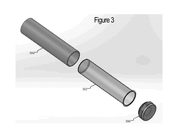
[0050] Figure 3 illustrates a fluid container for a cartridge in an aerosol
delivery
device. The fluid container in Figure 3 may be similar to the fluid container
illustrated in
Figure 2. In particular, a flexible bladder 302 may be the same as or similar
to the
bladder 206 shown in Figure 2. Likewise, a cap portion 306 may be the same as
or
similar to the cap 210 shown in Figure 2. Finally, the tube 304 may be either
the external
tube 202 or bladder support cylinder 204 shown in Figure 2.
[0051] The flexible bladder 302 may be a flexible bag or similar material.
In one
embodiment, the bladder 302 may be a latex material or a thin plastic. The
flexibility of
the bladder 302 may allow for pressure changes or temperature changes that
would
otherwise disrupt a sealed tank (i.e. non-flexible container), such as
leakage. In
11
CA 02998763 2018-03-14
WO 2017/048782 PCT/US2016/051638
particular, the flexible bladder 302 may equalize the pressure exterior to the
reservoir and
the inside pressure of the reservoir. The bladder 302 can adapt and adjusts
for any
pressure changes.
[0052] The seal of the bladder 302 may be a porous membrane within the cap
306.
In other words, the cap 306 may form an elastomeric seal on the open end of
the bladder.
The tube 304 may be open-ended for allowing for expansion/contraction of the
bladder
302. The cap 306 may be referred to as a plug or seal and provide a means for
controlling
and generating fluid flow from the bladder 302 to the heating element. Ceramic
may be
used for the cap 306 because it can be porous enough to allow a light fluid
flow to a wick
with the heating element. In particular, a silica wick may be in contact with
a ceramic (or
other porous material) in the cap 306 which receives fluid that is transported
to or near the
heating element. Other materials other than a ceramic may be utilized with the
cap 306
that allow for fluid flow from the bladder 302. For example, cellulose acetate
or a porous
plastic may be used for the cap 306. The cap 306 may be encased in a silicone
boot to
prevent leakage except for a desired amount through the porous material of the
cap 306.
[0053] Figure 4 illustrates the fluid container of Figure 3 in a closed
state. In
particular Figure 4 illustrates the cap 406 coupled to a tube 404 to seal the
bladder 402.
The sealing of the bladder 402 prevents leakage of the fluid, but the cap 406
can still
allow fluid flow from the bladder through a porous material 408. The porous
material
408 may include a ceramic, plastic, or other porous material that weeps fluid
from the
bladder 402. The fluid may be held in the bladder and the air flow (from a
user inhaling
described with respect to Figure 5) may trigger fluid flow from the bladder
302. The
sealing of the bladder is further discussed below with respect to Figures 6-
15. Figure 4
illustrates the flexible nature of the bladder 402. In particular, the bladder
402 may
collapse as fluid is dispensed from the bladder 402. The collapsed portion 403
of the
bladder 402 results from the bladder not being as full as fluid is removed.
The collapsing
of the bladder 402 may serve to maintain a balanced pressure within the
device. This
pressure mitigation may result in a more consistent and controllable amount of
fluid that
is dispensed through the porous material 408 by preventing potential leakage
that may
have been caused by pressure differentials.
[0054] Figure 5 illustrates air flow in the cartridge. There may be air
inlets through
which external air is received in the device. A wick 506 may include a heating
element
12
CA 02998763 2018-03-14
WO 2017/048782 PCT/US2016/051638
(e.g. coil) that vaporizes fluid that is absorbed onto the wick. The air flow
may pass over
or near the wick 506 and the heating element and then pass between the
external tube 504
and bladder 502. The external tube 504 may be the external tube 304 and the
bladder 502
may be the bladder 302 discussed above. In one embodiment the air path outside
of the
bladder 502 may be between the external tube 504 and a bladder support
cylinder 508.
The bladder support cylinder 508 may be used to support the bladder 502 and is
sealed
with a cap, while the external tube 504 results in an air path between the
bladder support
cylinder 508 and the external tube 504. As discussed above, the air flow may
be
generated by a user puffing (inhaling) on the device which results in a
suction effect that
pulls air through the air inlets.
[0055] Figure 6 illustrates a sealed bladder in a cartridge for an aerosol
delivery
device. A cap or seal may be used to seal the bladder to prevent leakage, but
to allow
fluid flow upon device usage. As used herein, the term cap or seal may refer
to multiple
components include a cap 606 and a porous material 608 shown in Figure 6.
Those
elements may be separate or may be combined as a singular cap/seal. The cap
606 may
include a porous material 608 that allows from fluid flow from the fluid
stored in the
bladder 602. The bladder 602 is disposed within an external tube 604 for
support. The
bladder is sealed off to the external tube 604 with a silicone seal 610. The
silicone seal
610 prevents fluid leakage, such that the fluid can only flow through the cap
606 and the
porous material 608. Although described as silicone in this embodiment, the
seal 610
may be formed of alternative materials that can fill the gap between the
bladder
connection to prevent fluid flow outside of the porous material 608. The
silicone seal 610
is further illustrated in Figure 7.
[0056] Figure 7 illustrates one embodiment of a sealing mechanism for
sealing a
bladder in a cartridge. The silicone seal 610 may include ridges 702 for
causing a
compression or friction fit between the bladder 602 and the external tube 604.
The
compression fit causes the flexible bladder 602 to be pressed against the
external tube 604
to prevent fluid leakage. In alternative embodiments, other seals may be
utilized (other
than a compression fit), including a screw mechanism, fastening mechanism, or
gluing
mechanism. The sealing that is used is designed to prevent fluid from the
flexible bladder
602 from leaking on the outside portion of external tube 604. Rather, the
fluid can only
pass through the cap 606 and the porous material 608. Because the bladder 602
is
13
CA 02998763 2018-03-14
WO 2017/048782 PCT/US2016/051638
flexible, it may need to be sealed in order to prevent this leakage. In one
embodiment, the
bladder 602 and the sealing mechanism is designed to be a one-time use or
disposable
cartridge that can be replaced.
[0057] Figure 8 illustrates an embodiment of a cartridge with a modified
air path. As
discussed, the air flow around the bladder may include a gap between the
bladder support
cylinder and the external tube. Figure 8 illustrates a modified air path 802
that includes
additional spacing between the bladder support cylinder and the external tube.
By
shrinking a connector, there may be a lip 804 that can be used for other
components (e.g.
ultrasonic).
[0058] Figure 9 illustrates an embodiment of an end of the cartridge in
Figure 8 with
the modified air path. In particular, the modified air path 902 is shown from
an end of the
cartridge. The modified air path 902 may include an opening that allows for
increased air
flow. This modified air path 902 may be a tube that is external to the bladder
and/or the
external tube but within an outside housing of the aerosol device.
[0059] Figure 10 illustrates a cartridge with a valve connection. The
internal bladder
may be held within an external container (e.g. external tube or cylindrical
support). There
may be a seal plate with an elastomeric valve that connects with a porous
material (e.g.
porous ceramic) for transporting the fluid during usage of the device. The
valve may
function to hold in the fluid unless it is activated and it allows liquid to
seep into the
porous ceramic which may contact a wick with a heating element for the
vaporization
process.
[0060] Figure 11 illustrates a closed state of the elastomeric valve shown
in Figure
10. The elastomeric valve shown in Figure 10 may be in a closed state when
fully
extended out from the bladder. The elastomeric valve is in a steady state 1102
awaiting
displacement.
[0061] Figure 12 illustrates an open state of the elastomeric valve shown
in Figure
10. The elastomeric valve shown in Figure 10 may be in a closed state when
pressed
upwards towards the bladder. The elastomeric valve is in a depressed state
1202 in which
the valve has been opened through displacement. In one embodiment, the user
may apply
the pressure that depresses the valve as shown in and described with respect
to Figure 13.
[0062] Figure 13 illustrates another elastomeric valve. A user may
physically press a
portion 1302 (e.g. button) that presses into the valve. The pressure on the
valve creates
14
CA 02998763 2018-03-14
WO 2017/048782 PCT/US2016/051638
an open fluid path when the elastomeric portion is displaced. The elastomer in
the
relaxed position would seal the openings. The opening of the valve may be by
displacement rather than pressure. In one embodiment, the sealed/closed state
may be at
manufacture and when the user adds the cartridge to their aerosol delivery
device, the
pressing of the cartridge into the device may cause the pressure needed to
activate the
valve and create a fluid path. This activation may be a one-time activation
(i.e. when the
cartridge is installed) or may be needed prior to each usage. For a disposable
cartridge,
the flexible bladder can remain in a sealed/closed state (with no leakage)
until the
cartridge is installed.
[0063] Figure 14 illustrates a sealed state of the cartridge. In
particular, the center
plunger may activate the release or opening of the elastomeric valve. Further,
Figure 14
illustrates the flow path in a closed state. The cartridge may include the
elastomeric valve
shown and described with respect to Figures 10-13. Fluid flow may be
completely
blocked in a sealed state. Upon manufacture and prior to usage, the cartridge
may be in
the sealed state. Upon first usage, a user may depress the valve to trigger
the open state
shown in Figure 15. Figure 15 illustrates the flow path being open. The open
state is
created when the valve is depressed which opens a fluid flow path from the
bladder
through the ceramic material. The center plunger may activate the opening of
the
elastomeric valve. The open state may be referred to as an activated state.
[0064] In alternative embodiments, the elastomeric valve may be replaced
with
another component. For example, there may be other components, such as a
membrane,
that seals the bladder in a closed state, but upon activation provides fluid
flow from the
bladder. The activation may include an electronic activation (e.g. press a
button) or a
physical activation (e.g. user depresses end of the device to touch or
displace the
membrane).
[0065] In an alternative embodiment, the reservoir storing the aerosol
precursor
substance or the fluid intended for aerosol formation may have the form of at
least one
capsule or otherwise possess a capsule-type of format and configuration. That
is, an
aerosol precursor substance can be adapted to have a form so as to segregate,
or otherwise
create physical separation for, that aerosol precursor. A typical capsule-type
configuration is provided by an inner region or core of aerosol precursor
components, and
an outer region or shell that acts as a wall or barrier structure to define
the shape and
CA 02998763 2018-03-14
WO 2017/048782
PCT/US2016/051638
volume of the inner region; as well as entrap, contain or encapsulate the
aerosol
precursor, thus providing storage or positioning of aerosol precursor in a
manner so that
the aerosol precursor is physically separated from other components of the
aerosol
delivery device into which that capsule is incorporated. If desired, a diluent
material may
be incorporated within the inner region of the capsule along with the aerosol
precursor
substance. Representative diluents are set forth in U.S. Patent No. 8,695,609
to Dube et
al.; and 2014/0053855 to Hartman et al., each of which are herein incorporated
by
reference. Preferably, each capsule is enclosed or sealed in such a way that
the aerosol
precursor substance does not leak from the capsule or may not be accessible
from the
capsule, prior to desired conditions of use.
[0066] Most
preferably, a representative capsule is such that the outer shell or wall
has sufficient resiliency and integrity to maintain encapsulation of the inner
components
during normal conditions or storage and handling; but can be broken to release
the
encapsulated inner components during conditions of normal use. For example,
the
capsule can be composed of a shell material so as to have a somewhat rigid
exterior, or
the capsule can have a somewhat flexible overall consistency. The outer wall
or shell
material of the capsule may be any of the following materials: proteins,
polysaccharides,
starches, waxes, fats, natural and synthetic polymers, and resins. Exemplary
materials
for use in the shell may include gelatin, acacia (gum arabic), polyvinyl
acetate,
potassium alginate, carob bean gum, potassium citrate, carrageenan, potassium
polymetaphosphate, citric acid, potassium tripolyphosphate, dextrin, polyvinyl
alcohol,
povidone, dimethylpolysiloxane, dimethyl silicone, refined paraffin wax,
ethylcellulose,
bleached shellac, modified food starch, sodium alginate, guar gum, sodium
carboxymethylcellulo se, hydroxypropyl cellulose, sodium citrate,
hydroxypropylmethylcellulose, sodium ferrocyanide, sodium polyphosphates,
locust
bean gum, methylcellulose, sodium trimetaphosphate, methyl ethyl cellulose,
sodium
tripolyphosphate, microcrystalline wax, tannic acid, petroleum wax, terpene
resin,
tragacanth, polyethylene, xanthan gum, and polyethylene glycol. If desired,
the capsule
can be over-coated with an outer barrier or seal on the outer region with a
coating or
moisture barrier. U.S. Pat. Pub. No. 2014/0053855 to Hartman et al. further
describes
capsule materials and is herein incorporated by reference.
16
CA 02998763 2018-03-14
WO 2017/048782 PCT/US2016/051638
[0067] The capsule is opened or activated to release the encapsulated
contents.
Typically, activation is performed by breaking, crushing, or melting of the
capsule; and
such activation most preferably is initialized by the user of the aerosol
delivery device.
For example, the user may either press a button to provide crushing of the
capsule, or
initiate an electronic signal that can further initiate chemical or physical
action upon the
capsule. Additionally, inhalation (i.e. when the flow sensor is triggered) may
result in a
physical crushing of the capsule or production of heat can act to degrade the
physical
integrity of the capsule wall, and hence release the inner, encapsulated
contents of the
capsule. The activation may be initialized by the user. For example, the user
may either
press a button, or inhalation (i.e. when the flow sensor is triggered) may
activate the
capsule. The initialization may include either a chemical reaction to break
down the
capsule, heating to break down the capsule, or some other electrical signal
that breaks the
capsule.
[0068] A capsule most preferably is positioned within the aerosol delivery
device
such that it can be broken when desired, and such that the contents of the
capsule can be
made available for aerosol production or for the enhancement of aerosol that
is produced
by the aerosol delivery device. As such, it is highly preferable, that
contents released
from the capsule are located in in the vicinity of the wicking components or
resistance
heating element of the aerosol delivery device (e.g., the capsules can be in
contact with,
or in a location sufficiently close to, the components of the aerosol delivery
device that
generate heat or exhibit increased temperature during conditions of use. Thus,
the
contents of the capsule, which include aerosol precursor components, can be
subjected to
heat generated for aerosol formation, and hence can be vaporized for aerosol
formation.
[0069] Numerous ways of handling breakable capsules and incorporating those
breakable capsules into components of smoking articles and vapor delivery
systems have
been proposed. For example, various types of capsules suitable for use in
smoking
articles, smoking article components that incorporate breakable capsules, and
equipment
and techniques associated with manufacturing those smoking article components,
are
proposed in U.S. Pat. Nos. 6,631,722 to MacAdam et al.; 7,479,098 to Thomas et
al.;
7,833,146 to Deal; 7,984,719 to Dube et al.; 7,972,254 to Stokes et al.;
8,186,359 to
Ademe et al.; 8,262,550 to Barnes et al.; 8,308,623 to Nelson et al.;
8,353,810 to
Garthaffner et al.; 8,381,947 to Garthaffner et al.; 8,459,272 to Karles et
al.; 8,739,802 to
17
CA 02998763 2018-03-14
WO 2017/048782 PCT/US2016/051638
Fagg; 8,905,243 to Dixon et al. and 9,055,768 to Henley et al.; US Pat. App.
Pub. Nos.
2010/0184576 to Prestia et al.; 2011/0053745 to They et al.; 2011/0271968 to
Carpenter et
al.; to Henley et al. and 2013/0085052 to Novak III, et al.; and U. S. Pat.
App. Ser. No.
14/835962, filed August 26, 2015 to Ademe; which are incorporated herein by
reference. Additionally, representative cigarette products that possess filter
elements
incorporating breakable capsules have been marketed throughout the world under
the
brandnames such as "Marlboro W-Burst 5," "Kent iSwitch," "Kool Boost," "Camel
Lights with Menthol Boost," "Camel Crush," "Camel Silver Menthol," "Camel
Filters
Menthol," and "Camel Crush Bold." Furthermore, representative types of vapor
delivery
systems that incorporate breakable capsules have been proposed in U.S. Pat.
Pub. Nos.
2014/0261486 to Potter and 2015/0059780 to Davis; and U.S. Pat. App. Ser. No.
14/282,768 to Sears et al., filed May 20, 2014; which are incorporated herein
by
reference.
[0070] Exemplary types of capsules, capsule ingredients, capsule
configurations and
formats, capsule sizes, capsule properties and capsule preparation techniques
are set forth
in U.S. Pat. Nos. 5,223,185 to Takei et al.; 5,387,093 to Takei; 5,882,680 to
Suzuki et al.;
6,719,933 to Nakamura et al.; 7,754,239 to Mane; 6,949,256 to Fonkwe et al.;
7,984,719
to Dube et al.; 8,470,215 to Zhang and 8,695,609 to Dube et. al.; U.S. Pat.
App. Pub. Nos.
2004/0224020 to Schoenhard; 2005/0196437 to Bednarz et al.; 2005/0249676 to
Scott et
al. and 2014/0053855 to Hartmann et al.; and PCT WO 03/009711 to Kim and PCT
WO
2014/170947 to Iwatani; which are incorporated herein by reference.
Additionally,
examples of representative types of capsules and capsule components have been
commercially available as "Momints" by Yosha! Enterprises, Inc. and "Ice
Breakers
Liquid Ice" from The Hershey Company; and representative types of capsules and
capsule components have be incorporated into chewing gum, such as the type of
gum
marketed under the tradename "Cinnaburst" by Cadbury Adams USA.
[0071] Representative encapsulated components can vary. One example of an
encapsulated formulation includes propylene glycol, glycerin, nicotine,
organic acids and
flavoring agents. An example of a suitable capsule is composed of an outer
shell that
possesses chemical and physical properties sufficient to provide a sealed
container of
good integrity for the encapsulated components. For example, such a shell can
be
provided using components comparable to use used to create those capsules used
for the
18
CA 02998763 2018-03-14
WO 2017/048782 PCT/US2016/051638
production of capsules used in filter elements of cigarettes marketed under
the brand
name "Camel Crush" by R. J. Reynolds Tobacco Company.
[0072] Figure 16 illustrates a cartridge 1600 for an aerosol delivery
device including
one or capsules. Figure 16 is similar to the embodiment shown in Figure 2,
except the
fluid container 202 with the flexible bladder 206 is replaced with one or more
capsules
1603 in a container 1602. Although eight capsules 1603 are illustrated in
Figure 16, there
may be just a single capsule for providing the aerosol precursor substance or
there may be
many more capsules with that substance. In an alternative embodiment, the
aerosol
precursor substance may be located in the container 1602 (e.g. in a flexible
bladder) while
capsules may be used for flavoring of that substance or to provide ingredients
other than
flavoring agents, such as nicotine. In particular, the capsule may act as a
supplement to
the aerosol precursor substance which may be present in a separate fluid
container from
the capsule. In an alternative embodiment, the capsule may be in a fluid
container that
includes the aerosol precursor substance and they are mixed upon activation of
the
capsule. The fluid container may be a flexible bladder as discussed above.
[0073] The overall shape of a capsule can vary. Typically, representative
capsules
are generally spherical in shape. However, the outer shell of the capsule can
be adapted
to have shapes that can be characterized as being, for example, generally
cylindrical,
bean-shaped, ovaloid or elongated in nature. Figure 17 illustrates alternative
embodiments of capsules. The capsules 1603 in Figure 16 are merely exemplary
and may
be in different shapes. Figure 17 illustrates capsules of different shapes. In
addition, the
capsules may be different sizes. There may be a single large capsule or many
smaller
microcapsules. Figure 17 illustrates a tubular capsule 1702, a square capsule
1704, an
oval or egg shaped capsule 1706, or a round/circular/spherical capsule 1708.
The shapes
shown in Figure 17 are merely exemplary. Activation of those capsules may be
similar to
or the same as the capsules 1603 in Figure 16.
[0074] The size of the capsule can vary. For example, a relatively large
sized capsule
that employed to replace the collapsible bladder, the capsule can have an
overall size that
in comparable to that of the previously described collapsible bladder. The
capsule also
can be relatively small; and as such, for example, a plurality of
microcapsules (e.g., about
50 to about 200 of such small capsules) can be incorporated within each
aerosol delivery
device. Additionally, spherical capsules having diameters of about 0.5 mm to
about 3
19
CA 02998763 2018-03-14
WO 2017/048782 PCT/US2016/051638
mm can be incorporated within each aerosol delivery device; and in such a
circumstance,
an exemplary aerosol delivery device can incorporate 1 such capsule to about
10 capsules.
[0075] Figure 18 illustrates an alternative cartridge 1800 for an aerosol
delivery
device including one or capsules disposed adjacent the heating element. In
particular, the
cartridge 1800 illustrates that the one or more capsules 1803 may be disposed
or located
adjacent the heating element 1814. The heating element 1814 may include a wick
and
heater. The wick receives the aerosol precursor substance or other fluid from
activation
of the capsules 1803. Based on the proximity with the capsules 1803 the
heating element
1814 may result in the melting of the capsules 1803 or a portion of the
capsules 1803. In
other words, activation of the capsules 1803 may be through melting from the
heating
element 1814. A flow-tube 1812 or terminal support may be support the heating
element
1814 so that the capsules 1803 are contained and located adjacent the heating
element
1814.
[0076] Figure 19 illustrates a breaking mechanism for the capsules. In
particular,
there may be a moveable element 1902 (similar to the embodiment for opening
the
elastomeric valve discussed above) which breaks or activates the capsules
1903. As
described in the embodiment with an elastomeric valve which is activated for
generating
a fluid flow path, the capsules 1903 may be activated by being broken or
crushed (e.g.
microcapsules) by the breaking mechanism. The capsules 1903 may be broken by a
force
or stress applied by a user with the moveable element 1902 upon usage of the
device.
The force may include compressive force applied to the exterior or shell
(i.e., a
mechanical force such as squeezing or twisting) to rupture and release the
substance in
the capsules 1903.
[0077] In an alternative embodiment, the capsule(s) 1903 may be located
adjacent the
moveable element 1902. The direct force from the moveable element 1902 may
cause
breakage of the capsule(s) 1903. In an embodiment similar to that shown in
Figure 18,
the capsule(s) 1903 may be adjacent the heating element.
[0078] The foregoing description of use of the article(s) can be applied to
the various
example implementations described herein through minor modifications, which
can be
apparent to the person of skill in the art in light of the further disclosure
provided herein.
The above description of use, however, is not intended to limit the use of the
article but is
provided to comply with all necessary requirements of disclosure of the
present
CA 02998763 2018-03-14
WO 2017/048782 PCT/US2016/051638
disclosure. Any of the elements shown in the article(s) illustrated in the
Figures or as
otherwise described above may be included in an aerosol delivery device
according to the
present disclosure.
[0079] Many modifications and other implementations of the disclosure set
forth
herein will come to mind to one skilled in the art to which these disclosure
pertain having
the benefit of the teachings presented in the foregoing descriptions and the
associated
drawings. Therefore, it is to be understood that the disclosure are not to be
limited to the
specific implementations disclosed and that modifications and other
implementations are
intended to be included within the scope of the appended claims. Moreover,
although the
foregoing descriptions and the associated drawings describe example
implementations in
the context of certain example combinations of elements and/or functions, it
should be
appreciated that different combinations of elements and/or functions may be
provided by
alternative implementations without departing from the scope of the appended
claims. In
this regard, for example, different combinations of elements and/or functions
than those
explicitly described above are also contemplated as may be set forth in some
of the
appended claims. Although specific terms are employed herein, they are used in
a
generic and descriptive sense only and not for purposes of limitation.
[0080] The illustrations of the embodiments described herein are intended
to provide
a general understanding of the structure of the various embodiments. The
illustrations are
not intended to serve as a complete description of all of the elements and
features of
apparatus and systems that utilize the structures or methods described herein.
Many other
embodiments may be apparent to those of skill in the art upon reviewing the
disclosure.
Other embodiments may be utilized and derived from the disclosure, such that
structural
and logical substitutions and changes may be made without departing from the
scope of
the disclosure. Additionally, the illustrations are merely representational
and may not be
drawn to scale. Certain proportions within the illustrations may be
exaggerated, while
other proportions may be minimized. Accordingly, the disclosure and the
figures are to
be regarded as illustrative rather than restrictive.
[0081] It is intended that the foregoing detailed description be understood
as an
illustration of selected forms that the invention can take and not as a
definition of the
invention. It is only the following claims, including all equivalents that are
intended to
define the scope of the claimed invention. Finally, it should be noted that
any aspect of
21
CA 02998763 2018-03-14
WO 2017/048782
PCT/US2016/051638
any of the preferred embodiments described herein can be used alone or in
combination
with one another.
22