Note: Descriptions are shown in the official language in which they were submitted.
CA 02998774 2018-03-15
WO 2017/050977 PCT/EP2016/072709
1
MULTI-USE ACOUSTIC LEVITATION TRAP
FIELD OF INVENTION
The present invention pertains to the field of device for manipulating
particles in a fluid.
In particular, the present invention relates to a device suitable for use as
an acoustic
resonator for manipulating particles in a fluid by means of acoustic waves.
BACKGROUND OF INVENTION
Acoustic waves can be used to handle or sort particles in a fluid by means of
an acoustic
force field. In the conventional techniques, known in the prior art, acoustic
resonators
comprises a cavity wherein one of the walls comprises an acoustic wave
generator and
the opposing wall serves as passive reflector. The ultrasonic wave generated
is reflected
and the wave superposition is known as a standing wave: at least one acoustic
pressure
node is created at a given positon along a dimension of a cavity of an
acoustic resonator
by providing a resonance condition for the acoustic wave. Particles
manipulation with
ultrasonic standing waves is known as a powerful tool for handling, moving or
trapping
particles in microfluidics devices.
For instance, US patent 7,373,805 discloses an acoustic resonator comprising
an
ultrasonic transducer glued to a coupling plate, an acoustic resonator and a
spacer
arranged between the coupling plate and the acoustic resonator and defining a
resonant
cavity. The coupling plate, the spacer and the acoustic resonator are held in
place between
a base and a top plate secured with screws. The screws must be strongly
tightened in order
to limit leakages of fluid filling the resonant cavity. Furthermore, the
screwing between
the base and the top plate, which defined the thickness of the resonant
cavity, must be
precisely controlled in order to ensure a regular thickness.
Within acoustic resonator, the thickness of the resonant cavity is indeed of
the utmost
importance as the resonance frequency is achieved by reaching the following
condition:
A
w = n. ¨ wherein w is the thickness of the resonator, n is the number of
pressure nodes of
2
CA 02998774 2018-03-15
WO 2017/050977 PCT/EP2016/072709
2
the standing waves and k the wavelength equal to ¨c; wherein cf is the speed
of sound in
the fluid filling the resonant cavity of the resonator and f is the acoustic
frequency.
Consequently, the resonator disclosed in US 7,373,805 requires a complicated
assembly
and may exhibit leakages.
US patent application 2013/0327130 also discloses acoustic resonators
comprising four
layers: a transducer, a coupling steel layer, a spacer and an acoustic
reflector. The spacer
is assembled in sandwich between the coupling steel layer and the acoustic
reflector with
neoprene glue. Therefore, the resonator disclosed in US 2013/0327130 cannot be
reused;
especially the spacer cannot be changed in order to change the size of the
resonant cavity.
There is thus a need for an easy-to-use acoustic resonator, avoiding leakage
of fluid and
wherein the resonant cavity may be opened and accessible and wherein the
spacer may
be easily changed in order to change the size of the resonant cavity.
Especially, as the
device of the invention may be used with living objects, there is a particular
need for a
device which may be easily disassembled and cleaned, e.g. autoclaved.
Moreover, the acoustic resonators of the prior art are designed for handling
only a small
amount of particles -from 1 to several hundred- within microfluidic devices.
US 7,373,805 discloses indeed the use of particles of diameter in the order of
li.tm and
US 2013/03271430 discloses that the particles have an average size of about 50
nm to
about 51Am. There is therefore also a need for devices suitable for the
analysis, separation
and collection, without complex manipulation, of large particles, especially
large living
particles such as cells or cluster of cells, having an average size from
0.11.tm to few
hundreds micrometers.
SUMMARY
To that end the present invention relates to a device, suitable for use as an
acoustic
resonator, comprising a base adapted to be coupled to at least one acoustic
wave
generator, a spacer comprising an aperture and a reflector, wherein:
- the base comprises a protruding part having a thickness t;
CA 02998774 2018-03-15
WO 2017/050977 PCT/EP2016/072709
3
- the aperture of the spacer is complementary to the protruding part of the
base;
- the device further comprises a housing having an aperture complementary
to the
protruding part of the base and the inner edge of the aperture of the housing
has
the same thickness t than the protruding part; and
- the housing
is positioned between the spacer and the reflector, such that the
thickness of the inner edge of the spacer defined the thickness of a cavity
between
the protruding part and the reflector.
Within the device of the present invention, the base, the spacer and the
housing are held
in place due to the protruding part of the base inserted within the apertures
of the spacer
and the housing without glue. The spacer may thus be easily replaced and the
resonant
cavity may be accessed. Moreover, the device of the present invention avoids
leakage of
fluid as the fluid should follow a tortuous path to flow out of the resonant
cavity.
According to one embodiment, the protruding part is axisymmetric, preferably
cylindrical, rhombohedral, parallelepiped or ribbon-shaped.
According to one embodiment, the device further comprises a supporting base
and a top
part, wherein the base, the spacer, the housing and the reflector are held in
position
between the supporting base and the top part. According to one embodiment, the
supporting base extends outwardly from the base; the top part encompasses the
base, the
spacer, the housing and the reflector; and the supporting base and the top
plate are secured
together, for instance with screws. According to one embodiment, the device
further
comprises a gasket ensuring tightness between the supporting base and the top
part.
According to one embodiment, the protruding part comprises at least one inlet
and at least
one outlet. According to one embodiment, the base, the protruding part and/or
the housing
comprises a material selected from metal or plastic. According to one
embodiment, the
reflector comprises an optically transparent material selected from glass,
quartz or plastic.
According to one embodiment, the protruding part comprises an optically
transparent
material selected from glass, quartz or plastic. According to one embodiment,
the top part
comprises at the top an optically transparent window. According to one
embodiment, the
spacer comprises a material selected from polyimide or a polyethylene
terephthalate.
CA 02998774 2018-03-15
WO 2017/050977 PCT/EP2016/072709
4
The present invention also relates to an acoustic resonator comprising the
device
according to the invention and at least one acoustic wave generator coupled to
the base.
According to one embodiment, the at least one acoustic wave generator is
located below
the protruding part of the base. According to one embodiment, the at least one
acoustic
wave generator is an ultrasonic wave generator. According to one embodiment,
the at
least one acoustic wave generator is a piezo transducer. According to one
embodiment,
the at least one acoustic wave generator is ring-shaped.
The present invention further relates to a method of trapping particles in a
fluid
comprising the steps of:
i. providing an acoustic resonator according to the invention;
ii. introducing a fluid comprising particles into the cavity;
iii. selecting the frequency f such that the path length of the standing
wave in
the cavity is a multiple of 1/2 of the wavelength of the sound wave therein;
and
iv. trapping the particles.
DEFINITIONS
In the present invention, the following terms have the following meanings:
- "Acoustic resonator" refers to a device using acoustic waves to apply
forces on
particles to be manipulated.
- "Levitation" refers to the fact that acoustic force counteracts gravity
force preventing
species from settling down in the cavity and maintaining them in a controlled
position.
- "Optically transparent" refers to a part exhibiting high light
transmittance (above
50%, preferably above 75%, more preferably above 90%) over at least a portion
of
the visible light spectrum (about 400 to about 700 nm).
CA 02998774 2018-03-15
WO 2017/050977 PCT/EP2016/072709
DETAILED DESCRIPTION
The following detailed description will be better understood when read in
conjunction
with the drawings. For the purpose of illustrating, the device is shown in the
preferred
embodiments. It should be understood, however that the application is not
limited to the
5 precise arrangements, structures, features, embodiments, and aspect
shown. The drawings
are not drawn to scale and are not intended to limit the scope of the claims
to the
embodiments depicted. It should be understood that the spatial descriptions
(e.g.,
"above", "below", "up", "down", "top", "bottom", "on", "under", etc.) made
herein are
for purposes of illustration only, and that devices of the present invention
can be spatially
arranged in any orientation or manner.
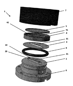
According to a first aspect, as depicted in figures 1 and 2, this invention
relates to a device
1, suitable for use as an acoustic resonator, comprising a base 2 adapted to
be coupled to
at least one acoustic wave generator, a spacer 3 comprising an aperture 31 and
a reflector
5, wherein:
- the base 2 comprises a protruding part 21 having a thickness t;
- the aperture of the spacer 31 is complementary to the protruding part of the
base
21;
- the device further comprises a housing 4 having an aperture 41 complementary
to
the protruding part of the base 21 and the inner edge of the aperture of the
housing
41 has the same thickness t than the protruding part of the base 21; and
- the housing 4 is positioned between the spacer 3 and the reflector 5, such
that the
thickness of the spacer 3 defined the thickness of a cavity between the
protruding
part of the base 21 and the reflector 5.
According to one embodiment, the housing 4 is positioned between the spacer 3
and the
reflector 5, thereby arranging a cavity between the protruding part 21 and the
reflector 5;
such cavity having a thickness identical to that of the inner edge of the
spacer 3.
According to one embodiment, the protruding part 21 is inserted within the
aperture of
the spacer 31 and the aperture of the housing 41.
CA 02998774 2018-03-15
WO 2017/050977 PCT/EP2016/072709
6
According to one embodiment, the base 2 is a plate. According to one
embodiment, the
base 2 is adapted to be a coupling layer between a resonant cavity and the at
least one
acoustic wave generator. According to one embodiment, the base 2 is
cylindrical (i.e. has
a circular periphery).
According to one embodiment, the base 2 comprises a protruding part 21
protruding
upwardly from the base 2. According to one embodiment, the protruding part 21
has a
constant thickness. According to one embodiment, the thickness of the
protruding part 21
is ranging from 1 to 10 mm, preferably from 2 to 5 mm.
According to another embodiment as depicted in figure 4, the protruding part
21 is hollow
and comprises a peripheral groove 211 configured to accommodate a bottom plate
212,
acting as the bottom plate of the cavity. Said bottom plate 212 has a
thickness t. According
to one embodiment, the thickness t of the bottom plate 212 is ranging from 1
to 10 mm,
preferably from 2 to 5 mm. According to one embodiment, said peripheral groove
211 comprises an 0-ring configured to ensure tightness of the cavity.
According to one embodiment, the protruding part 21 is axisymmetric. According
to one
embodiment, the protruding part 21 is cylindrical, rhombohedral,
parallelepiped or
ribbon-shaped.
According to one embodiment, the area of the protruding part 21 is ranging
from 1 to
10 cm2, preferably from 1 to 3 cm2.
According to one embodiment, the base 2 comprises at least one protruding part
21.
According to one embodiment, the base 2 comprises more than one protruding
part 21.
According to one embodiment, the base 2 comprises more than one hollow
protruding
part 21, each comprising a bottom plate 212.
According to one embodiment, the spacer 3 is a plate. According to one
embodiment, the
spacer 3 is a plate having a constant thickness. According to one embodiment,
the spacer
3 is cylindrical (i.e. has a circular periphery). According to one embodiment,
the thickness
of the spacer 3 is ranging from 101.tm to 20001.tm, preferably from 501.tm to
10001.tm, more
preferably from 50 to 5001.tm.
CA 02998774 2018-03-15
WO 2017/050977 PCT/EP2016/072709
7
The spacer 3 comprises an aperture 31. According to one embodiment, the
aperture of the
spacer 31 is complementary to the protruding part 21. According to one
embodiment, the
shape of the aperture of the spacer 31 is complementary to the shape of the
protruding
part 21. According to one embodiment, the aperture of the spacer 31 has a
shape adapted
to cooperate with the protruding part 21. According to one embodiment, the
aperture of
the spacer 31 has the same shape as the protruding part 21, such that the
protruding part
21 may be inserted through the aperture of the spacer 31 without mechanical
play, the
spacer 3 lying on the base 2. Due to the protruding part 21, the spacer 3 is
locked in
translation in the plane of the base 2. According to one embodiment, the shape
of the
protruding part 21 prevents rotation of the spacer 3 relative to the base 2.
In said
embodiment, the protruding part 21 is not cylindrical but may be rhombohedral,
parallelepiped or ribbon-shaped.
According to one embodiment, the spacer 3 and the protruding part 21 does not
exhibit
the same thickness. According to one embodiment, the thickness of the spacer 3
is smaller
than the thickness of the protruding part 21. According to one embodiment, the
ratio
between the thickness of the spacer 3 and the thickness of the protruding part
21 is lower
than 0.5. According to one embodiment, the ratio between the thickness of the
spacer 3
and the thickness of the protruding part 21 is ranging from 0.001 to 0.5,
preferably from
0.005 to 0.2, preferably about 0.01.
According to one embodiment, the spacer 3 comprises a material selected from
polyimide
or polyethylene terephthalate.
According to one embodiment, the spacer 3 comprises at least one aperture 31.
According
to one embodiment, the spacer 3 comprises more than one aperture 31.
According to one embodiment, the reflector 5 is a plate. According to one
embodiment,
the reflector 5 has a constant thickness. According to one embodiment, the
reflector 5 is
cylindrical (i.e. has a circular periphery). According to one embodiment, the
reflector 5
does not comprise any aperture. According to one embodiment, the thickness of
the
reflector 5 is ranging from 500[tm to 4 mm, preferably from 1 mm to 2 mm.
CA 02998774 2018-03-15
WO 2017/050977 PCT/EP2016/072709
8
According to one embodiment, the reflector 5 comprises a material chosen
among:
organic or mineral glasses, quartz, thermoplastic materials or metallic
alloys. According
to one embodiment, the reflector 5 is made from titanium alloy such as TA6V.
According
to one embodiment, the reflector 5 comprises an optically transparent
material. According
to one embodiment, the reflector 5 comprises an opaque material.
According to one embodiment, the housing 4 is a plate. According to one
embodiment,
the housing 4 has a constant thickness, especially the inner edge of the
aperture 41 has a
constant thickness. According to one embodiment, the thickness of the housing
4,
especially the thickness of the inner edge of the aperture 41 has the same
thickness t than
the thickness of the protruding part of the base 21. According to one
embodiment, the
housing 4 is cylindrical (i.e. has a circular periphery). According to one
embodiment, the
housing 4 comprises an aperture 41. According to one embodiment, the thickness
of the
housing 4 is ranging from 1 to 10 mm, preferably from 2 to 5 mm.
According to one embodiment, the aperture of the housing 41 is complementary
to the
protruding part 21. According to one embodiment, the shape of the aperture of
the housing
41 is complementary to the shape of the protruding part 21. According to one
embodiment, the aperture of the housing 41 is adapted to cooperate with the
protruding
part 21. According to one embodiment, the aperture of the housing 41 has the
same shape
as the protruding part 21, such that the protruding part 21 may be inserted
within the
aperture of the housing 41 without mechanical play, the housing 4 lying on the
spacer 3.
Due to the protruding part 21, the housing 4 is locked in translation along
the plane of the
base 2. According to one embodiment, the shape of the protruding part 21
prevents
rotation of the housing 4 relative to the base 2. In said embodiment, the
protruding part
21 is not cylindrical but may be rhombohedral, parallelepiped or ribbon-
shaped.
According to one embodiment, the housing 4 comprises at least one aperture 41.
According to one embodiment, the housing 4 comprises more than one aperture
41.
According to one embodiment, the base 2, the protruding part 21 and/or the
housing 4
comprises a material selected among: organic or mineral glasses, quartz,
thermoplastic
materials, metal such as for instance aluminum or stainless steel. According
to one
CA 02998774 2018-03-15
WO 2017/050977 PCT/EP2016/072709
9
embodiment, the base 2, the protruding part 21, the housing 4 and/or the
reflector 5
comprises or consist of a material having high acoustic impedance, preferably
ten times
greater than the acoustic impedance of the fluid filing the resonant cavity.
According to
one embodiment, the protruding part 21 and the reflector 5 are made from
different
materials. According to one embodiment, the protruding part 21 and the
reflector 5 are
made from the same material.
According to one embodiment, the protruding part 21 is made of an optically
transparent
material. According to one embodiment, the protruding part 21 is made of a
material
chosen among: organic or mineral glasses, quartz or thermoplastic materials.
According to one embodiment wherein the base 2 comprises a protruding part 21
with a
removable bottom plate 212, said bottom plate 212 is made of an optically
transparent
material. According to one embodiment, said bottom plate 212 is made of a
silicon wafer.
According to one embodiment, said bottom plate 212 is made of a material
chosen among:
organic or mineral glasses, quartz or thermoplastic materials.
According to one embodiment, the device comprises successively the base 2, the
spacer
3, the housing 4 and the reflector 5; with the protruding part of the base 21
inserted within
the aperture of the spacer 31 and the aperture of the housing 41, such that
the device
comprises a cavity between the protruding part 21 and the reflector 5, the
said cavity
having the same thickness than the thickness of the spacer 3. According to one
embodiment, the said cavity has a volume ranging from 200[LL to 2000[tL,
preferably
from 1000[iL to 2000[tL. On the contrary to the devices of the prior art, with
such volume
of cavity, more than one thousand, preferably more than hundreds of thousands
of
particles may be manipulated. Furthermore, such dimensions of cavity enable to
manipulate micron-sized particles.
According to one embodiment, as the spacer 3 and the housing 4 have a constant
thickness, the upper and lower wall of the cavity (i.e. the upper surface of
the protruding
part and the lower surface of the reflector) are parallel.
CA 02998774 2018-03-15
WO 2017/050977 PCT/EP2016/072709
According to one embodiment, the spacer 3 and/or the housing 4 do not have a
constant
thickness so that the upper and lower wall of the cavity (i.e. the upper
surface of the
protruding part and the lower surface of the reflector) are not parallel.
As the base 2, the spacer 3 and the housing 4 are not glued together; the
spacer 3 may be
5 easily changed in order to change the thickness of the cavity.
According to one embodiment, the housing 4 comprises a peripheral wall 42
protruding
upwardly for encasing the reflector 5 without mechanical play. According to
one
embodiment, the reflector 5 lies on the housing 4. According to one
embodiment, the
reflector 5 is not glued to the housing 4. According to one embodiment, the
reflector 5 is
10 glued or fixed to the housing 4. According to one embodiment wherein
there is no flow
of fluid within the cavity, the reflector may lie on the housing and be
maintained by
capillary forces without glue or fixation means.
According to one embodiment, the device further comprises a supporting base 6
and a top
part 7 enclosing together the base 2, the spacer 3, the housing 4 and the
reflector 5,
preferably without mechanical play. According to one embodiment, the base 2,
the spacer
3, the housing 4 and the reflector 5 are held in position between the
supporting base 6 and
the top part 7.
According to one embodiment, the supporting base 6 extends downwardly and
outwardly
from the base 2. According to one embodiment, the top part 7 encompasses the
base 2,
the spacer 3, the housing 4 and the reflector 5. According to one embodiment,
the
supporting base 6 and the top plate 7 are secured together, for instance with
screws.
According to one embodiment, the device further comprises a gasket 8 ensuring
tightness
between the supporting base 6 and the top part 7.
According to one embodiment, the top part 7 comprises at the top an optically
transparent
window. According to one embodiment, the cavity can be observed thought the
optically
transparent window with an electronic microscope in order, for example, to
study the
acoustic interaction between particles.
CA 02998774 2018-03-15
WO 2017/050977 PCT/EP2016/072709
11
According to one alternative embodiment as depicted in figure 4, the device 1
further
comprises a supporting base 6 comprising a protruding part 61 having a shape
complementary to the shape of the protruding part 21 of the base 2, so that
the protruding
part 61 of the supporting base 6 may be inserted within the protruding part 21
of the base
2. According to said embodiment, when an acoustic wave generator is fixed to
the
protruding part of the supporting base 61, the acoustic wave generator may be
coupled to
the protruding part of the base 21. According to one embodiment, the device
does not
comprises a top part 7 and the supporting base 6, the housing 4 and the base 2
are bolted,
screwed or maintained by any means known by one skilled in the art. According
to one
embodiment, the protruding part of the supporting base 61 is made of an
optically
transparent material. According to one embodiment, the protruding part of the
supporting
base 61 is made of a material chosen among: organic or mineral glasses, quartz
or
thermoplastic materials.
According to one embodiment, the protruding part 21 comprises at least one
inlet 22 and
at least one outlet 23. According to one embodiment, said inlet 22 and outlet
23 are
suitable for filing the cavity and/or for creating a flow of fluid within the
cavity.
According to one embodiment, the base and/or the supporting base comprises an
inlet
channel and an outlet channel, fluidly connected to respectively the inlet and
the outlet of
the protruding part. According to one embodiment the inlet 22 and the outlet
23 are not
located at the center of the protruding part 21. According to one embodiment,
the flow
rate depends on the particles to be manipulated, the cavity volume and the
acoustic force
field applied. For example, the fluid may flow at a flow rate ranging from
0.01 mL/min
to 100 mL/min. According to one embodiment, more than one flow rate may be
implemented during the manipulation of particles. According to one embodiment,
the
fluid is a liquid. According to one embodiment, the liquid is selected from a
water-based
liquid, an organic liquid, a biological liquid such as blood plasma, a tissue
culture media
such as LB (Lysogeny Broth) basic growing bacteria culture medium, a ionic
liquid or
complex fluids such as polymeric solutions leading to scaffold fabrication.
CA 02998774 2018-03-15
WO 2017/050977 PCT/EP2016/072709
12
According to one embodiment wherein the protruding part 21 comprises a bottom
plate
212, the bottom plate may comprise at least one inlet and at least one outlet
suitable for
filing the cavity and/or for creating a flow of fluid within the cavity.
According to one embodiment, the protruding part 21 does not comprise any
inlet or
outlet. In said embodiment, the device is used for analysis e.g. of a drop or
drops of a
solution disposed in the cavity without any flow (i.e. before positioning the
reflector on
the housing).
According to one embodiment, the protruding part 21 comprises at least two
inlets: at
least on inlet introduces the sample and at least one inlet introduces a
reactive (e.g. for
cleaning, diluting or testing the sample). According to one embodiment, the
protruding
part 21 comprises at least two outlets. According to one embodiment, each
outlet is fluidly
connected to valves which open or close depending of the sample to be
collected.
According to one embodiment, the thickness of the protruding part 21 about one
outlet is
different from the thickness of the protruding part 21 about the other outlet.
According to one embodiment, as depicted in figure 2, the protruding part 21
comprises
a plurality of separators 24, such as for instance pins, protruding upwardly
such that the
resonant cavity comprises a plurality of compartments in fluid communication
between
each other. According to one embodiment, the separator has a thickness equal
or lower
than the thickness of the inner edge of the spacer 3. According to one
embodiment, each
compartment is adapted to be couple with an acoustic wave generator. According
to one
embodiment, the said compartments may have different thicknesses, or may be
used with
different mediums, different frequencies and/or different acoustic wave
generators.
According to one embodiment, in order to parallelize the manipulation of
particles, the
base may comprises more than one protruding part and the spacer and the
housing may
comprise more than one aperture complementary to the protruding parts. Within
said
embodiment, different particles may be manipulated or the same particles may
be
manipulated within different fluids.
CA 02998774 2018-03-15
WO 2017/050977 PCT/EP2016/072709
13
According to a second aspect, as depicted in figure 3, the invention also
relates to an
acoustic resonator 11 comprising the device 1 according to the invention and
at least one
acoustic wave generator 9 coupled to the base.
According to one embodiment, the at least one acoustic wave generator is
cylindrical,
square-shaped, rod-shaped or ring-shaped.
According to one embodiment, the at least one acoustic wave generator 9 is
glued or fixed
to the base 2.
According to one embodiment, the at least one acoustic wave generator 9 is
glued or fixed
to the protruding part 61 of the supporting base 6. According to one
embodiment, the
height of the protruding part 61 is configured so that when at least one
acoustic wave
generator 9 is glued or fixed to said protruding part 61, the at least one
acoustic wave
generator 9 is coupled to the protruding part 21. Said coupling may be a dry
coupling or
may use any coupling means.
According to one embodiment, the at least one acoustic wave generator 9 is
located below
the protruding part of the base 21. According to one embodiment, a plurality
of acoustic
wave generators 9 is located below the protruding part of the base 21.
According to one
embodiment, the base 2 is etched on the back of the protruding part 21 for
encasing the
at least one acoustic wave generator 9.
According to one embodiment, the at least one acoustic wave generator 9 is
located at the
top of the protruding part of the supporting base 61. According to one
embodiment, a
plurality of acoustic wave generators 9 is located at the top of the
protruding part of the
supporting base 61.
According to one embodiment, the at least one acoustic wave generator 9 is an
ultrasonic
wave generator. According to one embodiment, the at least one acoustic wave
generator
9 is a piezo transducer.
According to one embodiment, the area of the optically transparent part of the
reflector 5
is larger than the area of the at least one acoustic wave generator, thereby
enabling to
investigate upstream and downstream of the acoustic force field.
CA 02998774 2018-03-15
WO 2017/050977 PCT/EP2016/072709
14
According to one embodiment, the reflector 5, the protruding part 21 of the
base 2 and
the protruding part 61 of the supporting base 6 comprises an optically
transparent
material, and the at least one acoustic wave generator 9 is at least one ring-
shaped acoustic
wave generator. Said embodiment enables optical analysis of the cavity by
means of
transmission microscopy.
According to a third aspect, the invention also relates to a method of
trapping particles in
a fluid using the device according to the invention.
Especially, the method of trapping particles in a fluid comprises the steps
of:
i. providing an acoustic resonator according to one embodiment of the
present invention;
ii. introducing a fluid comprising particles into the cavity;
iii. selecting the frequency f such that the path length of the standing wave
in
the cavity is a multiple of 1/2 of the wavelength of the sound wave therein;
and
iv. trapping the particles.
According to one embodiment, the method of trapping particles may be
implemented
without flow of fluid or with continuous or pulsatile flow of fluid.
According to one embodiment, the trapping of particles may be implemented by
levitation, selective focusing, MSF, flow trapping sorting or selective
focusing trapping.
Therefore, the acoustic resonator of the invention is a multi-use acoustic
trap, preferably
a multi-use acoustic levitation trap. According to one preferred embodiment,
the trapping
of particles may be implemented by levitation.
Levitation is generated by acoustic standing waves, preferably ultrasonic
standing waves
originating an ultrasonic radiation pressure profile characterized by nodes
and antinodes
in the cavity thickness. Nodes and antinodes can be placed anywhere within the
cavity
thickness, even close to walls. When nodes are placed at the middle plane of
the cavity,
for instance, the radiation force that is a focusing force pulls particles
away from the walls
preventing particle-wall interactions. In other configuration, by slightly
changing the
frequency, the nodal position can be modified by moving it in controlled way
toward the
CA 02998774 2018-03-15
WO 2017/050977 PCT/EP2016/072709
walls: the equilibrium position of the particles can thus be modulated through
the whole
cavity thickness.
By pushing species toward either wall or by placing the nodes or the antinodes
close the
walls it is also possible to generate and study particle-wall interactions, as
well as to
5 generate partial segregations based on the fact that relaxation to the
nodal plane is size-
selective.
According to one embodiment, the acoustic resonator of the invention may be
used with
non-living particles and with living particles such as for instance cells,
bacteria, viruses,
DNA, proteins and the like.
10 According to one embodiment, the particles are nano- or micron-sized
particles, i.e.
having at least one size ranging from 0.1 to few hundreds micrometers,
preferably 0.1 to
9001.tm, more preferably from 1 to 5001.tm, even more preferably from 10 to
4001.tm.
According to one embodiment, the particles to be manipulated or trapped are
selected
from rigid, elastic, mineral or biological particles. According to one
embodiment, the
15 particles to be manipulated or trapped are selected from algae,
microorganisms, bacteria,
viruses, DNA, proteins or leavening. According to one embodiment, the
particles to be
manipulated or trapped are selected from colloidal emulsion, non-colloidal
emulsions,
ionic fluids or active fluids. According to one embodiment, the particles to
be manipulated
or trapped are selected from cells, parts of cells such as cell debris, or
cluster of cells;
such as for instance blood cells, cancellous cells or epithelial cells.
According to one
embodiment, the particles to be manipulated or trapped are selected from
phospholipids,
liposomes or vesicles. According to one embodiment, the particles to be
manipulated or
trapped are selected from micro-particles such as metallic microfibers; or
nanoparticles
such as carbon nanotubes or mixture thereof. According to one embodiment, the
method
of trapping particles is implemented with self-propelled objects such as
bacteria in
biological or ionic fluids or micro-/nano-robots. According to one embodiment,
the fluid
comprising the particles is an organic or an inorganic fluid.
According to one embodiment, the upper surface of the protruding part and/or
the lower
surface of the reflector may comprise a sensing medium enabling detection of
particles.
CA 02998774 2018-03-15
WO 2017/050977 PCT/EP2016/072709
16
According to one embodiment, the upper surface of the protruding part and/or
the lower
surface of the reflector may be labelled with specific antibodies in order to
trap specific
cells labeled with surface antigen receptors flowing through the cavity,
either by an
imposed flow or by the flow generated by the acoustic force field.
According to one embodiment, the acoustic resonator of the invention may be
used in
tissue engineering by aggregating and manipulating different cells.
According to one embodiment, the method of trapping may also comprises the
step of
aggregating the particles for the fabrication of two- or three-dimensional
constructs, for
instance for producing filters.
According to one embodiment, the device of the invention and/or the acoustic
resonator
of the invention is temperature controlled by any means known by one skilled
in the art
such as for instance a Pelletier system or a heating circuit within the base.
While various embodiments have been described and illustrated, the detailed
description
is not to be construed as being limited hereto. Various modifications can be
made to the
embodiments by those skilled in the art without departing from the true spirit
and scope
of the disclosure as defined by the claims.
BRIEF DESCRIPTION OF THE DRAWINGS
Figure 1 is an exploded view of the device according to one embodiment of the
present
invention.
Figure 2 is an exploded view of the device according to another embodiment of
the
present invention.
Figure 3 is an exploded view of an acoustic resonator comprising a plurality
of acoustic
wave generators according to one embodiment of the present invention.
Figure 4 is an exploded view of the device according to another embodiment of
the
present invention.
CA 02998774 2018-03-15
WO 2017/050977 PCT/EP2016/072709
17
Figure 5 illustrates the density profile of two species of particles during
the separation of
said particles by means of the acoustic resonator of the invention.
REFERENCES
1 ¨ Device suitable for use as an acoustic resonator;
11 ¨ Acoustic resonator;
2 ¨ Base;
21 ¨ Protruding part;
211 ¨ Groove;
212 ¨ Bottom plate;
22 ¨ Inlet;
23¨ Outlet;
24 ¨ Separator;
3 ¨ Spacer;
31 ¨ Aperture of the spacer;
4¨ Housing;
41 ¨ Aperture of the housing;
42 ¨ Peripheral wall;
5 ¨ Reflector;
6 ¨ Supporting base;
61 ¨ Protruding part;
7¨ Top part
8 ¨ Gasket;
9 ¨ Acoustic wave generator.
CA 02998774 2018-03-15
WO 2017/050977 PCT/EP2016/072709
18
EXAMPLES
The present invention is further illustrated by the following examples.
Example 1: Bacteria Manipulation
Bacteria suspension is injected within the cavity of the acoustic resonator of
the present
invention. The concentration of bacteria may vary from high concentration to
very diluted
samples.
An acoustic force field is implemented within the cavity by means of the
acoustic wave
generator and several thousands or millions of bacteria are trapped under the
acoustic
force field, thereby inducing a stable aggregate in levitation.
A stable colony of bacteria can therefore be studied by observing its time
evolution in
function of the suspending medium. The entire colony can be trapped and the
medium
modified in order to establish new equilibriums. It is also possible within
the present
acoustic resonator to eliminate specific bacteria by modifying the medium.
Once the sample has been manipulated, the cavity may be demounted and the
sample may
be collected after the assay in order to be submitted to other studies with
any technique
known to one skilled in the art.
Example 2: Separation of particulate species
A suspension comprising different species or different concentrations of
species is
injected within the cavity of the acoustic resonator of the present invention.
Species could
differ on size or even on acoustic properties such as acoustic impedance.
Within the
present example, a suspension of two species of polystyrene particles of 7[tm
diameter
(A) and of 2[tm diameter (B) are injected within the cavity.
By selecting a suitable frequency, the different species are trapped and
positioned at
different distances from the walls of the cavity. Once different equilibrium
positions have
been reached, a flow is established in such a way that only one kind species
remains
CA 02998774 2018-03-15
WO 2017/050977 PCT/EP2016/072709
19
trapped while the other(s) are eluted, and the sample collected is filtered of
the trapped
species.
As acoustic force depends on particles size, acoustic force is much stronger
for bigger
species, at least 40 times stronger for species of 7ium diameter relative to
species of 2[tm
diameter. Therefore, two effects are used: a) the time required for species to
reach the
equilibrium position is much smaller for bigger species; and b) the force to
keep trapped
bigger species is much stronger.
Consequently, when a flow is established; the average position of different
species is
different generating a differential transport along the cavity.
Within the present example, the smallest species can be eluted while the 7ium
particles
remain trapped. Figures 5 illustrate the density profile with peaks
corresponding to the
two species. Especially, figures 5A, 5B, 5C, 5D and 5E show successively the
different
positions of both species, after respectively 0, 2, 3, 4 and 5 seconds.