Note: Descriptions are shown in the official language in which they were submitted.
METHOD AND APPARATUS FOR RECYCLING WELLS FOR ENERGY
PRODUCTION IN A GEOTHERMAL ENVIRONMENT
FIELD OF THE INVENTION
[0001] The present invention relates to a method and apparatus for reuse
of unused drilled wells and areas predetermined for well installation which
optionally include wells and/or well bores to capture geothermal heat
energy within a formation of the area.
BACKGROUND OF THE INVENTION
[0002] It is widely known that there tens of thousands of unused wells and
well sites, particularly in Alberta. These having been disparagingly referred
to as "garbage" and "litter". They are unused for reasons such as being
uneconomically feasible, having run dry amongst other reasons. There is
reluctance among owners to abandon the well sites in view of the
significant capital investment to effect abandonment. Accordingly, owners
simply attempt to placate the disdain by stating that the unused wells could
be used in the future and thus abandonment would be premature.
[0003] The situation has become a financial juggernaut considering that it is
estimated that greater than 80,000 wells are currently unused in Alberta.
[0004] It has been reported that:
1
CA 2998782 2018-03-21
"The number of oil and gas wells abandoned by industry has expanded
dramatically as depressed commodity prices forced operators into
bankruptcy.
Alberta's inventory of wells without an owner financially capable of cleaning
them up expanded greatly over the last 2 years to 2,500+, a clear indicator
of the turmoil that rattled Alberta during the recession.
The surge means taxpayers will be on the hook to pay landowners annual
rents to compensate them for use of their properties until the sites are
returned to a natural state.
And property owners are seeking compensation in record numbers.
"We're just dealing with the tip of the iceberg," said Daryl Bennett, director
of the Alberta Surface Rights Federation, adding the tally of abandoned
wells doesn't include licences involved in bankruptcy proceedings or those
still being processed by the energy regulator" I Reid Southwick, Calgary
Herald, December 28, 2016]
[0005] In the realm of the prior art, proposals have been promulgated to
assuage the issue. Geothermal energy has been considered and systems
are being tested to assess the feasibility of exploiting the geothermal
gradient. It has been discussed to use a series of tubes to be inserted in
the ground for water within the tubes to absorb the heat and recirculate it
to the surface and subsequently into a recovery device for use of the heat.
2
CA 2998782 2018-03-21
[0006] The geothermal gradient is generally defined as the rate of
temperature increase relative to increasing depth in the interior of the
Earth. Quantitatively, this represents approximately 25 C to 35 C for each
kilometer. As such, this amount of energy is too substantive too leave
unused. The union of this energy with the unused wells has resulted in
renewed interest with the unused wells as evinced in the prior art.
[0007] Roussy, in United States Patent No. 8,132,631, issued March 13,
2012, teaches a geothermal loop installation where a sonic drill is provided
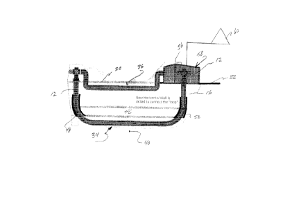
for rotating and vibrating a drill string into the ground. Fluid is provided
within the interior volume of the string.
A geothermal transfer loop is positioned within the interior volume of the
drill string and the drill string is removed from the ground.
[0008] Although useful in certain scenarios, the limitation with this
arrangement relates to the confined interior volume of the drill string and
further only a small area of the loop is exposed to a geothermal zone. This
inherently limits efficient heat transfer.
[0009] United States Patent No.8,375,716, issued February 19, 2013, to
Ramaswamy et al. discloses an electrical generating power method and
apparatus for sub-sea purposes and incorporates an organic Rankin
cycle positioned within a pressure vessel. This forms a series of connected
vessels positioned adjacent, on or in the sea floor. Fluid is circulated
through the vessels in order to generate mechanical shaft power which is
subsequently converted to electrical power.
3
CA 2998782 2018-03-21
[0010] The interconnection of wells is recognized by Henderson, in United
States Patent No. 3,941,422, issued March 2, 1976. In the teachings, two
wells are drilled into the salt bed, with one being essentially vertically
arranged and the drilled distally from the first well and deflected towards
the first well in such a manner that the bottom of the deflected well
approaches within a selected distance of the bottom of the first well.
Subsequently, the salt is fractured by the use of the liquid fracturing
technique in one or the other or both of the two wells, to enable fluid flow
between the two wells. The salt is mined by fresh water injection with
recovery of saturated salt solution from the other well.
[0011] It is clear that Henderson teaches paired wells generally connected,
but the teachings do not contemplate an energy recovery or heat exchange
system driven by geothermal energy.
[0012] WellStar Energy, in a press release dated December 1, 2016 briefly
touches on the possibility of incorporating unused wells with a geothermal
loop for energy recovery, however no specific details are mentioned in this
regard or for interconnection of wells for thermal management.
[0013] Chevron, in an undated video disclosure, taught gas well
interconnection at the Congo River Canyon Crossing Pipeline Project. An
interconnecting pipeline was run from one side of the river to the other for
supplying gas. Again, this was a specific use for well interconnection. Well
recycle and interconnection in a geothermal loop was not discussed.
4
CA 2998782 2018-03-21
[0014] GreenFire Energy, in an article dated 2017,discuss a looped
geothermal energy recovery system. Rather than using preexisting gas/oil
wells for repurposing, new wells are drilled. This does nothing to control
improperly maintained unused wells and in fact may contribute to new
problems. The disclosure is silent on techniques used to effect the loop and
further does not contemplate clustering and consolidation necessary for
maximum efficiency.
[0015] It would be most desirable to have a methodology and apparatus
that unified the energetically favorable geothermal gradient with the reuse /
recycling of preexisting unused wells for generating power while also
significantly reducing the deleterious consequences of improperly
maintained suspended well. Further, it would be beneficial to reuse areas
with predetermined suitability for well installation which optionally include
wells for geothermal energy recovery.
[0016] The present invention uniquely correlates the thermodynamic
parameters requisite to efficiently recover geothermal energy, mitigate
poorly maintained wells and produce power with no greenhouse gas
emissions.
SUMMARY OF THE INVENTION
[0017] One object of one embodiment of the present invention is to provide
an improved method and apparatus suitable for reuse of areas
predetermined for well installation which optionally include wells or well
bores for capturing geothermal energy within a formation of the area.
CA 2998782 2018-03-21
[0018] One aspect of one embodiment of the present invention is to provide
a method and apparatus for improving the efficiency and economics of
unused wells or well sites.
[0019] A further aspect of one embodiment of the present invention is to
provide a method for geothermal energy recovery, comprising:
providing an area with predetermined suitability for well installation;
providing a first new well and a second new well adjacent said first well;
connecting, in a closed loop fluid connection, each said first new well and
said second new well at least a section of each said loop being in contact
with a geothermal zone;
circulating a working fluid into said closed loop to recover energy from said
geothermal zone; and
recovering thermal energy from said working fluid.
[0020] With the predetermined suitability, i.e. zoning, permitting, etc. in
place for a selected area, more commonly referred to as a "greenfield",
such areas can be repurposed and become attractive for geothermal
energy recovery, since the logistical requirements have been met. Further,
this repurposing facilitates opportunities for industrial users to facilitate
"
behind the fence" power generation. The benefits of such a situation are
immediately comprehensible.
6
CA 2998782 2018-03-21
[0021] A further aspect of one embodiment of the present invention is to
provide a method of converting preexisting unused wells in spaced relation
in a formation to capture heat energy, comprising:
providing an preexisting unused well;
forming a new well proximate said preexisting unused well;
linking said preexisting unused well and said new well in a continuous loop
in a geothermal zone and a second zone spaced from said geothermal
zone; and
circulating working liquid through said loop to capture heat from said
geothermal zone.
[0022] In this scenario, there is a blending of so called "brownfield"
technology with the "greenfield" technology in order to reuse existing sites
and still realize the geothermal benefits.
[0023] As a still further aspect of one embodiment of the present invention,
there is provided la geothermal energy recovery method, comprising:
providing a first new well and a second new well adjacent the
first well;
7
CA 2998782 2018-03-21
connecting, in a closed loop fluid connection, each first new
well and second new well at least a section of each said loop
being in contact with a geothermal zone;
circulating a working fluid into said closed loop to recover
energy from said geothermal zone;
recovering thermal energy from the working fluid; and
at least one of storing recovered thermal energy, generating
power from the recovered thermal energy and heating a
structure with the recovered thermal energy.
[0024] The latter aspect demonstrates the flexibility of the methodology.
The geothermal energy may be used to heat domiciles, factories, learning
institutions among a host of others while at the same time providing power
to such structures. This is achieved with the closed loop technology herein
which obviates pollution issues inherent with other energy sources to meet
increasingly demanding controls for the environment.
[0025] In respect of immediate advantages attributable to the technology
herein, the following are apparent:
8
CA 2998782 2018-03-21
[0026] A) The technology provides a viable alternative for energy
production once fossil fuel burning is phased out:
[0027] B) The technology obviates the economic drawbacks associated
with solar and wind energy production:
[0028] C) By incorporating existing wells and well sites which may be
dilapidated, leaking or otherwise rendered hazardous, these wells and well
sites will be modified and structurally improved when used in practicing the
method;
[0029] D) Retrofitting is an economically robust use of the unused wells and
well sites in view of the prohibitive costs inherent in repair, closure or
abandonment:
[0030] E) The geothermal driver for the method is continuously available 24
hours regardless of wind speed or overcast weather;
[0031] F) The geothermal gradient is substantially uniform throughout vast
areas and thus facilitates maximum flexibility in topographical layout of the
well network in any given area;
[0032] G) The steam separator and super heater system can accommodate
steam delivery upsets, where large amounts of carry over may occur over a
short time period;
9
CA 2998782 2018-03-21
[0033] H) Satellite configurations are possible of consolidated wells in order
to allow use of the greatest number of wells in a given area;
[0034] I) The technology completely avoids any calculated environmental
transgressions; a casing is simply used to connect wells, with the casing
carrying water between wells and a power production unit.
[0035] This enumeration of advantages is illustrative as opposed to
exhaustive.
[0036] Having thus generally described the invention, reference will now be
made to the accompanying drawings.
BRIEF DESCRIPTION OF THE DRAWINGS
[0037] Figure 1 is a schematic illustration of an array of unused wells;
[0038] Figure 2 is a view similar to Figure 1 illustrating the positioning of
new wells disposed within the unused wells;
[0039] Figure 3 is a first schematic representation of one embodiment of
the present invention where new wells are clustered with unused wells;
[0040] Figure 4 is a schematic representation invention where the clusters
are consolidated;
CA 2998782 2018-03-21
[0041] Figure 5 is a partial sectional detailed view of an unused well with a
new well and the interconnection there between;
[0042] Figure 5A is an enlarged section of the connection between the
extension of an unused well and casing;
[0043] Figure 6 is a view similar to Figure 5 illustrating the closed loop in
a
surface to surface arrangement;
[0044] Figure 7 is a schematic illustration of a further embodiment of the
present invention; and
[0045] Figure 8 is a schematic illustration of another embodiment of the
present invention.
[0046] Similar numerals used in the Figures denote similar elements.
DETAILED DESCRIPTION OF THE PREFERRED EMBODIMENTS
[0047] Referring now to Figure 1, shown is a schematic illustration of a
drilled area generally denoted by numeral 10 with a plurality of dispersed
unused wells 12.
[0048] Referring now to Figure 2, shown is a similar illustration to Figure 1,
however a plurality of new wells 16 through 30 have been drilled proximate
a respective unused well 12.
11
CA 2998782 2018-03-21
[0049] Turning to Figure 3, a main hub 32 is provided. Although not
specifically shown, hub 32 is effectively a manifold arrangement where
each of the new wells 14, 16, 18 and 20 are in fluid communication
discussed in greater detail herein after. From the hub 32, each of the new
wells 14, 16 and 18 are spaced from each other and unused well 12
associated with the hub 32. Each new well 14, 16 and 18 is in fluid
communication with a single proximate unused well 12. Fluid
communication is achieved by piping 34 and 36. Piping 34 is disposed
below the surface 38 and more specifically within a geothermal zone,
generally denoted by numeral 40. As is illustrated, piping 34 is disposed
above the surface 38 in the example, however it may be disposed below
surface 38 which will be shown in the advancing Figures.
[0050] Conveniently, hub 32 with the new wells 14,16, 18 in the example as
connected to a respective unused well 12 form clusters of recycled unused
wells.
[0051] For clarity, Figures 3 and 4 can be referenced together and the
loops 34 and 36 are absent in Figure 4 for purposes of clarity. A cluster can
be referenced in Figure 3 denoted by numeral 42. The clustering is
effective for linking additional clusters 42 as shown in Figure 4. The new
wells 14, 16 and 18 associated with a given hub 32 link other clusters 42 by
way of an unused well 12 from an adjacent cluster 42. Such a link is
referenced as 44 for purposes of explanation. In this manner, the clusters
42 are consolidated as an energy collecting system as opposed to a
random unproductive array of unused wells 12 shown in Figure 2. This
12
CA 2998782 2018-03-21
provides a high efficiency arrangement for collecting geothermal energy in
a closed loop surface to surface design.
[0052] Geothermal loops have been proposed ostensibly in the prior art
discussed supra, however, in mosaic, the prior art has not provided
adequate guidance in terms of the surface to surface energy recovery,
minimal geological invasiveness unified with consolidated recycling.
[0053] Turning now to Figure 5, shown is a side view of a simplified unused
well 12 connected to a hub 32. Existing well 12, owing to the fact that it was
initially purposed to operate within hydrocarbon bearing formation 46, must
be extended in depth to the geothermal zone 40. This may be achieved by
drilling and adding an extension 48 for communication with a horizontal
casing section 50. Casing 50 extends to new well 16, for example, via a
second extension 52. The connection terminates at the hub 32 which is in
fluid communication a manifold ( not shown ) associated with unused well
12.
[0054] Figure 5A is an enlarged view of the connection between the
extension 48 and a section 54 of the casing 50. This facilitates the
connection between the unused well 12 and new well 16 in a surface to
surface manner.
[0055] Figure 6 schematically illustrates a complete loop arrangement,
similar to Figure 2 with parts removed for clarity. As shown, loop 36
completes the surface 40 to surface 38 energy loop. In this embodiment,
loop 36 is shown in a subterranean disposition in spaced relation to loop
13
CA 2998782 2018-03-21
34, however it will be realized by those skilled that the same may be above
the surface depending on the specific requirements of the situation.
[0056] For efficiency, the horizontal casing 50 will not be fixedly secured
within the geothermal zone 40, but rather be in direct contact therewith.
This facilitates most efficient heat exchange from the zone 40.
[0057] In terms of a working liquid for circulation within the arrangement,
suitable choices will be apparent to those skilled.
[0058] Similarly, residence time the loops will be dictated by casing length,
material among other factors all of which can be determined by known
thermodynamic equations.
[0059] In order to use the energy captured by the system, connection to a
power converter device, globally denoted by numeral 58 may be
incorporated and optionally connected to a power grid 60 depending on
proximity considerations.
[0060] In view of the fact that the existing well 12 is deepened, includes an
extension 48 and any required fixative, the well 12 is effectively
structurally
restored. As is known from the discussion herein, such wells are often in
poor condition, leaking, etc. The instant technology is clearly beneficial in
this regard.
[0061] Turning to Figure 7, shown schematically are a variety of
implementations of the technology. Areas 62 are representative areas
14
CA 2998782 2018-03-21
which have been predetermined as suitable and permissible for well
installation. In this regard, the regulatory issues, permits, licenses, etc.
have been addressed and the areas are what is referred to as " greenfield"
areas. New wells, using the numbering convention from Figure 2 are
referenced as 16 through 30. The arrangement and interconnection is the
same as that which has been discussed in reference to Figures 3 through
7.
[0062] Areas 64 may be present in a plurality and may be connected at 66
and 68 in a manner similar to that shown in Figures 3 and 4.
[0063] Area 70 is the same as Figure 2 and is referred to a " brownfield"
area which is a mix of existing wells 12 and new wells 16 through 30. Areas
62 and 70 may be interconnected singly at 72 or in a plurality at 74 and 76.
[0064] As referenced previously, the brownfield areas 70 may be connected
as in Figure 4 at 78.
[0065] Further, at least one of areas 72, 74, 76 may be interconnected with
at least one of areas 70 at 80.
[0066]Figure 8 illustrates the use of the recovered heat energy to be used
not only for the power grid 60, but further for storage of the energy at 82
with suitable storage means known to those skilled. Further still, the energy
may be used to heat a structure 84. This is particularly appealing for
residential heat, but is envisioned for any structure. In this arrangement,
the
storage area 82 may be linked at 86 for energy supply to the structure 84.
CA 2998782 2018-03-21
[0067] By these additional embodiments, greenfield areas which are left
unused can be reused/recycled using the geothermal loop technology
embodiments established herein.
16
CA 2998782 2018-03-21