Note: Descriptions are shown in the official language in which they were submitted.
FUEL CELL WITH PARTICLE COLLECTORS
PROJECTING INTO ANODE CHAMBER
Technical Field
100011 This invention relates to metal-air fuel cells, such as zinc-air
fuel cells.
Background
100021 Metal-air fuel cells provide high energy efficiency and yet are low
cost with low environmental impact. The zinc-air fuel cell is an example of a
metal-air fuel cell. In a zinc air fuel cell, zinc metals are provided as
fuel, air is
provided as an oxygen source, and an aqueous alkaline solution, such as
potassium
hydroxide (KOH), is provided as an electrolyte. When an electric circuit is
closed,
the anode consumes zinc metal via the anode or negative electrode reaction,
Zn + 4KOH ¨> K2Zn(OH)4 +2K+ + 2e (1) E = -1.216 V
100031 Zinc metal is consumed as it reacts with potassium hydroxide,
potassium zincate is formed (K2Zn(OH)4) and electrons are released to an anode
current conductor.
100041 Oxygen is supplied to the cathode and reacts with H2O and electrons
on the cathode to fonn hydroxyl ions (OH-). The cathode or positive electrode
1
Date Recue/Date Received 2022-11-15
PCT/CA2016/051080
CA 02999069 2018-03-19
25 January 2017 25-01-2017
reaction is therefore,
1/202 + H20 + 2e --> 20H- (2) Eo =0.401 V
[0005] The hydroxyl ions from equation (2) and the potassium ions from
equation (1) then react with zinc metal again in equation (1) at the anode.
100061 According to this reaction scheme, the oxidation of zinc and the
reduction of oxygen cause the change of chemical energy into electrical
energy.
For the reactions to proceed over long times there must be a continuous supply
of
zinc metal and air as well as a means of constant flow of electrons from the
system,
i.e., connection to a load.
100071 In previous zinc-air implementations the metal electrodes have had
a
fixed quantity of zinc, limiting their available energy and having
rechargeability
drawbacks due to size augmentation of the electrodes upon cycling. Decreases
in
the electrode area leads to a decrease in power of the fuel cell system.
100081 Improved metal-air fuel cells are desirable.
Summary
100091 The inventions described herein have many aspects, some of which
relate to fuel cells, fuel cell stacks, metal-air fuel cell system, and
methods of
charging metal-air fuel cells.
2
AMENDED SHEET
PCT/CA2016/051080
CA 02999069 2018-03-19
25 January 2017 25-01-2017
100101 In one aspect a fuel cell is provided. The fuel cell comprises: a
cathode; an anode comprising an anode chamber and an anode current collector,
the anode chamber at least partially defined by the anode current collector;
and a
cathode chamber at least partially defined by the cathode. The anode chamber
comprises one or a plurality of anode flow channels for flowing an electrolyte
in a
downstream direction.
[0011] The anode current collector may comprise a plurality of particle
collectors projecting into the anode chamber to collect particles suspended in
the
electrolyte.
[0012] The plurality of particle collectors may be configured to perturb
the
flow of electrolyte through said anode chamber and encourage settling of the
particles on or between the particle collectors.
100131 The particle collector may comprise a laterally elongated member.
The laterally elongated member may extend up to a width of the anode flow
channel. The angle defined between the laterally elongated member and a planar
portion of the anode current collector in the upstream direction may be
between 10
to 90 degrees, or 20 to 80 degrees, or 30 to 70 degrees, or 90 to 120 degrees,
or 120
to 180 degrees. The height of the laterally elongated member relative to the
planar
portion of the anode current collector may range from 0.2 mm to 5.0 mm, or 0.5
to
3.0 mm, or 1.0 to 2.0 mm. The ratio of (i) a height of the laterally elongated
member relative to the planar portion of the anode current collector and (ii)
a
height of the anode chamber may range from 0.1 to 0.6, or 0.2 to 0.5, or 0.3
to 0.4.
3
AMENDED SHEET
PCT/CA2016/051080
CA 02999069 2018-03-19
25 January 2017 25-01-2017
[0014] The number of the particle collectors per linear centimeter may
range
from 0.5 to 10, or 1 to 5, or 1 to 2. The distance between adjacent particle
collectors may be less than a height of the particle collector relative to a
planar
portion of the anode current collector. The plurality of particle collectors
may be
arranged in an array configured to form a uniform bed of the particles on the
anode
current collector.
[0015] The anode chamber may comprise a parallel flow configuration or a
serpentine flow configuration. The anode flow channels may comprise length to
width ratios in the ranges of 50:1 to 2:1, 25:1 to 4:1, or 10:1 to 5:1. The
width of
the anode flow channels may range from 2 mm to 20 cm, 5 mm to 10 cm, or 1 cm
to 5 cm.
[0016] The cathode and anode current collector may be planar. The surface
area of the anode current collector may range from 1 cm2 to 1 m2.
[0017] The height of an electrolyte flow field within the anode chamber
may
be 0.5 mm to 4 mm, 1 mm to 3mm, or 2 mm.
[0018] The fuel cell may be a zinc-air fuel cell and the particles may be
zinc
particles. The electrolyte may be potassium hydroxide.
[0019] According to another aspect, a fuel cell stack is provided. The
fuel
stack comprising a plurality of fuel cells as described herein. The plurality
of fuel
cells may be oriented horizontally and stacked on top of one another to form
the
4
AMENDED SHEET
PCT/CA2016/051080
CA 02999069 2018-03-19
25 January 2017 25-01-2017
= =
fuel cell stack, or may be oriented vertically and stacked beside one another
to
form the fuel cell stack.
[0020] According to another aspect, a metal-air fuel cell system is
provided.
The metal-air fuel cell system comprises: a fuel cell as described herein; a
metal
electrolyzer comprising in fluid communication with an outlet of the fuel
cell; and
a tank in fluid communication with an outlet of the metal electrolyzer and an
inlet
of the fuel cell. The fuel cell may be a zinc-air fuel cell and the metal
electrolyzer
may be a zinc electrolyzer.
[0021] According to another aspect, a method of charging a metal-air fuel
cell is provided. The method comprises:
(a) orienting an anode chamber horizontally wherein a corresponding anode
current collector is positioned below the anode chamber;
(b)providing metal particles suspended in an electrolyte to flow through the
anode chamber;
(c) allowing a bed of the metal particles to form on the anode current
collector; and
(d)maintaining uniform formation of the bed.
[0022] Step (c) may comprise one or more of:
(i) maintaining the flow of the metal particles suspended in the
electrolyte at a predetermined flow rate;
(ii) periodically stopping the flow of the metal particles suspended in the
electrolyte; and
AMENDED SHEET
PCT/CA2016/051080
CA 02999069 2018-03-19
25 January 2017 25-01-2017
(iii) providing a plurality of particle collectors on the anode current
collector.
[0023] Step (d) may comprise providing a uniform flow of the electrolyte
through the anode chamber. Providing the uniform flow may comprise providing a
continuous pressure drop in a downstream direction in the anode chamber and a
minimal pressure drop in a direction normal to the downstream direction.
Providing the continuous pressure drop in the downstream direction and the
minimal pressure drop in the direction normal to the downstream direction may
comprise providing a parallel or serpentine flow path for the anode chamber.
Providing the parallel or serpentine flow path may comprise providing channels
for
the parallel or serpentine flow path defined by a length to width aspect ratio
of 50:1
to 2:1, 25:1 to 4:1, or 6:1 to 5:1.
[0024] Step (c) may comprise fonning the bed to a depth of 0.2 mm to 2.0
cm,
or 1 mm to 1.0 cm, or 2 mm to 4 mm, or 0.5 mm to 2 mm. Step (c) may comprise
forming the bed to a depth wherein a ratio of the depth to a height of the
anode
chamber ranges from 0.1 to 0.6, or 0.2 to 0.5, or 0.3 to 0.4.
[0025] Step (b) may comprise providing metal particles ranging in size
from
nm to 1 mm, 5 nm to 0.5 mm, or 5 nm to 0.3 mm.
[0026] The flow velocity of the electrolyte in the anode chamber may
range
from 1 cm3/s to 5000 cm3/s. The flow rate of the electrolyte in the anode
chamber
may range from 1 L/min. to 7 L/min, or 3 L/min. to 7 L/min or 3 L/min. to 5
L/min.
6
AMENDED SHEET
PCT/CA2016/051080
=
CA 02999069 2018-03-19 25 January 2017 25-01-2017
100271 The gauge pressure of the electrolyte in the anode chamber
may range
from 0.69 kPa to 103.4 kPa, or from 13.8 kPa to 68.9 kPa. The pressure drop
traversing the anode chamber may be less than 103.4 kPa.
100281 The metal particles may be zinc particles, and the
electrolyte may be
aqueous potassium hydroxide. The concentration of potassium hydroxide may be
% to 60 % by weight, or 20 % to 50 % by weight, or 30 % to 45 % by weight.
100291 The method may comprise drawing a current density of 50
mA/cm2or
more from the fuel cell. The method may comprise applying a load to the fuel
cell
and discharging for a period of 1 to 20 hours.
10030] The foregoing discussion merely summarizes certain aspects
of the
inventions and is not intended, nor should it be construed, as limiting the
inventions in any way.
Brief Description of Drawings
[0031] In drawings which show non-limiting embodiments of the
invention:
Figure 1A is a partial cutaway side view of a fuel cell according to an
embodiment of the invention;
Figure 1B is a partial cutaway side view, perpendicular to the view
shown in Figure 1A, of the embodiment shown in Figure 1A;
7
AMENDED SHEET
PCT/CA2016/051080
=
= CA 02999069 2018-03-19 25 January 2017 25-01-2017
=
Figure 2 is a close up partial cutaway side view of the embodiment
shown in Figure 1A;
Figure 3 is a partial top view of an anode chamber according to an
embodiment of the invention;
Figures 4A to 4F are partial cutaway side views of various
embodiments of the invention;
Figures 5A to 5C are partial top views of various anode chambers
according to embodiments of the invention; and
Figure 6A is a top view of a fuel cell according to an embodiment of
the invention;
Figure 6B is a top view of a fuel cell according to an embodiment of
the invention;
Figure 7 is a schematic view of a metal-air fuel cell system according
to an embodiment of the invention.
Description
[0032] Throughout the following description, specific details are
set forth in
order to provide a more thorough understanding of the invention. However, the
invention may be practiced without these particulars. In other instances, well
8
AMENDED SHEET
PCT/CA2016/051080
CA 02999069 2018-03-19
25 January 2017 25-01-2017
=
known elements have not been shown or described in detail to avoid
unnecessarily
obscuring the invention. Accordingly, the specification and drawings are to be
regarded in an illustrative, rather than a restrictive, sense.
100331 A number of directional conventions are employed in this
specification to help clarify their meaning, as follows:
= "upstream" and "downstream" as used herein relate to directions,
orientations, positions or arrangements of features relative to the flow of
electrolyte from the inlet of the anode chamber to the outlet of anode
chamber, wherein relative to a first position within the anode chamber from
the inlet of the anode chamber, a second position in the anode chamber
closer to the inlet along the flow path of the electrolyte is "upstream", and
a
third position within the anode chamber further away from the inlet along
the flow path of the electrolyte is "downstream";
= "lateral, "laterally" and the like as used herein relates to the
directions
normal to the flow of electrolyte from the inlet of the anode chamber to the
outlet of anode chamber or from the inlet of an anode channel to the outlet of
an anode channel;
= "horizontal" and "horizontally" as used herein refers to an orientation
parallel to the ground; and
= "top", "bottom", "above" and "below" as used herein refer to the
orientations, positions or arrangements of features when the anode chamber
is oriented substantially horizontally.
9
AMENDED SHEET
= PCT/CA2016/051080
CA 02999069 2018-03-19
25 January 2017 25-01-2017
=
[0034] The term "fuel cell' as used herein refers to an electrochemical
device
as would be understood by a person skilled in the art. The term "fuel cell"
includes,
without limitation, devices known as "flow batteries" and similar terminology.
[0035] The Willi "uniform" as used herein with reference to an anode bed
refers to an anode bed with an substantially even distribution of metal
particles.
[0036] The term "substantially" as used herein refers to the complete or
nearly complete extent or degree of an action, characteristic or result. For
example,
a "substantially" continuous pressure drop would mean that the pressure drop
is
either completely continuous or nearly completely continuous. The exact
allowable
degree of deviation from absolute completeness may in some cases depend on the
specific context. However, generally speaking the nearness of completion will
be
so as to have the same overall result as if total completion were obtained.
The use
of "substantially" is equally applicable when used in a negative connotation
to refer
to the complete or near complete lack of an action, characteristic or result.
For
example, "substantially" no pressure drop refers to either a complete lack of
pressure drop, or a lack of pressure drop so nearly complete that the effect
would
be the same as if there was no pressure drop. In other words, "substantially"
no
pressure drop means that there may still be a measurable pressure drop as long
as
there is no measurable effect thereof.
[0037] Conventional anode beds for zinc-air fuel cells are formed by one
of
two approaches. One approach is to form a dense bed of packed zinc particles
where the electrolyte is forced to flow through the bed at high pressure. The
inventors have determined at least two drawbacks with this approach. First,
the
AMENDED SHEET
amount of pressure that can be mechanically tolerated by a fuel cell limits
the
pumping pressure to below about 68948 Pa since higher pressures would place
too
much mechanical stress on the fuel cell. Second, reducing pumping pressure
limits
the range of particle sizes that can be used. A pumping pressure below 68948
Pa is
only useful in an anode bed where the mean particle size is above 200 microns;
using smaller particles would require pumping pressures that are too high,
e.g. as
high as 689476 Pa, in order to maintain sufficient zinc dissolution reactions.
[0038] An alternative approach is to pump a slurry or suspension of zinc
particles through the anode chamber. In the absence of a packed particle bed
the
pumping pressures are much lower, for example lower than 55.2 kPa. However
with this approach, the inventors have determined that the particles make only
transient contact with the anode current collector, and the current density
generated
is therefore limited by the number of transient contacts that are fottned at
any
instant.
[0039] In one embodiment, a fuel cell with a substantially horizontally-
oriented anode chamber is provided. Small metal particles, such as in the
range of
15 nm to 300 microns, suspended in electrolyte are pumped into the anode
chamber at low pressure, such as below 68.9 kPa. A dense bed of the metal
particles is formed on an anode current collector at low electrolyte pressures
by
gravitational settling and one or more of: controlling the electrolyte flow
rate;
intermittently stopping the electrolyte flow; and providing particle
collectors on the
anode current collector. The advantages of this approach include low
electrolyte
pressure (to reduce pumping energy costs and mechanical stress) and small
metal
11
Date Recue/Date Received 2022-11-15
PCT/CA2016/051080
CA 02999069 2018-03-19
25 January 2017 25-01-2017
particle size (to increase electrical current generation), which are made
possible by
the anodic reaction occurring along the top of the anode bed, as well as
through the
anode bed. At any moment, more metal particles are in contact with each other
and
with the anode current collector. Thus the total surface area of metal
particles
contributing to the electrode reaction and generation of electrical current is
much
greater, in turn leading to higher energy efficiency. Electrolyte flow along
and
through the anode bed also removes oxidized metal reaction products from the
reaction site.
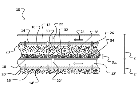
100401 Figure 1A shows part of a fuel cell stack 10 according to one
embodiment of the invention. Fuel cell stack 10 is comprised of a plurality of
vertically stacked fuel cells. Figure 1A shows a first fuel cell 2, and part
of an
identical, partial second fuel cell 2' below fuel cell 2. In some embodiments
the
fuel cell stack may only comprise a single fuel cell. In some embodiments,
such as
in fuel cell stack 10, the fuel cells are oriented horizontally and stacked on
top of
one another to form a fuel cell stack. In some embodiments, the fuel cells are
oriented vertically and stacked beside one another to form a fuel cell stack.
Figure
1B shows the alternate side view of fuel cell stack 10 as seen perpendicular
to
Figure 1A.
100411 Fuel cell 2 of fuel cell stack 10 includes a cathode chamber 12,
cathode 14, anode chamber 16, anode current collector 18 and a separator 20.
The
section of fuel cell 2' of fuel cell stack 10 shown in Figure lA includes
cathode
chamber 12', cathode 14', and anode chamber 16'. Separator 20 prevents
electrical
contact between the cathode 14 and the anode chamber 16 but allows for ionic
conductivity between the two. A contact pin 22' electrically connects anode
12
AMENDED SHEET
PCT/CA2016/051080
CA 02999069 2018-03-19
25 January 2017 25-01-2017
current collector 18 to cathode 14' to close the circuit. In an alternate
arrangement
contact pin 22' and anode current collector 18 are integrally &allied. The
components of fuel cell 2 of fuel cell stack 10 will be described in greater
detail
herein but it will be understood that the features and functions of the
components
of other fuel cells of fuel cell stack 10, including fuel cell 2', will
correspond to
those of the components of fuel cell 2.
[0042] Suitable construction and configuration of cathode chamber 12 and
cathode 14, as known in the art, are provided to extract oxygen from air
flowing
though cathode chamber 12 (direction of air flow represented by arrow 24) by
electrochemical reduction of oxygen at cathode 14, and to allow migration of
formed hydroxide into anode chamber 16 (direction of oxygen
extraction/reduction
and hydroxide ion migration represented by arrow 26). In some embodiments,
such
as in fuel cell stack 10, cathode 14 is generally planar.
[0043] Anode chamber 16 is shaped to permit metal particles 30 suspended
in
an electrolyte to flow therethrough in a downstream direction as represented
by
arrow 28. In some embodiments, the metal particles may be zinc, aluminum,
beryllium, calcium, iron, lithium, magnesium, sodium, titanium, or a mixture
of
such metals. In the illustrated embodiment, metal particles 30 are zinc
particles. In
some embodiments, the metal particles may range in size from 5 nm to 1 mm, or
5
nm to 0.5 mm, or 5 nm to 0.3 mm.
[0044] In some embodiments, the electrolyte may be alkaline, such as an
aqueous alkali hydroxide. In some embodiments, the aqueous alkali hydroxide
may
be aqueous potassium hydroxide or aqueous sodium hydroxide. In some
13
AMENDED SHEET
PCT/CA2016/051080
=
CA 02999069 2018-03-19 25 January 2017 25-01-2017
embodiments, the concentration of the aqueous alkali hydroxide may range from
% to 60 % by weight, or 20 % to 50 % by weight, or 30 % to 45 % by weight. In
other embodiments, the electrolyte may be non-alkaline.
[0045] In some embodiments, such as in fuel cell 2, anode current
collector
18 is made of a material with high conductivity and high stability in aqueous
alkaline solutions. In example embodiments, the anode current collector may be
stainless steel, nickel, iron, titanium, copper, gold, silver, magnesium,
indium, lead,
or carbon. In other embodiments alloys or conductive oxides of combinations of
these and other elements are employed. In some embodiments, anode current
collector 18 is generally planar. Anode current collector 18 is disposed
opposite of
cathode 14 with anode chamber 16 at least partially defined therebetween. In
some
embodiments, the surface area of each of cathode 14 and anode current
collector
18 may range from 1 cm2 to 1 m2. In an example embodiment, the surface area of
cathode 14 and anode current collector 18 are each about 500 cm2 and separated
by
about 3 mm.
[0046] In some embodiments, such as in fuel cell 2, anode current
collector
18 includes a plurality of particle collectors 32 projecting into anode
chamber 16.
Particle collectors 32 may be of any shape and configuration suitable for
collecting
particles 30 suspended in the electrolyte and flowing through anode chamber
16. In
some embodiments, particle collectors 32 are of suitable size, shape,
configuration
and/or array for trapping particles 30 and facilitating their formation into
an anode
bed 34 on anode current collector 18. In some embodiments, particle collectors
32
are of suitable size, shape, configuration and/or array for establishing a
series of
obstacles that perturb the flow of electrolyte through anode chamber 16 and
14
AMENDED SHEET
PCT/CA2016/051080
CA 02999069 2018-03-19
25 January 2017 25-01-2017
encourage the settling of particles on or between the particle collectors.
Figures 4A
to 4F show non-limiting examples of side views of other possible shapes of
particle
collectors 32. In some embodiments particle collectors 32 may be porous, or
have
holes, slits, and the like to enhance circulation of electrolyte. In a
particular
embodiment, particle collectors 32 are formed from a conductive mesh. The mesh
should limit pore sizes to a suitable size, shape, configuration and/or array
to
facilitate trapping particles.
[0047] In a particular embodiment particle collectors 32 are constructed
of
the same conductive material as anode current collector 18. In other
embodiments
particle collectors 32 may be constructed of a different conductive material
or non-
conductive material. In a particular embodiment, particle collectors 32 are
integrally formed with anode current collector 18. In other embodiments
particle
collectors 32 may be formed separately and then coupled to anode current
collector
18. In some embodiments the surface of anode current collector 18 is provided
with sufficient particle collectors 32 to form a uniform anode bed 34.
[0048] As shown in Figure 2, each particle collector 32 at least
partially
defines an opening 35 for receiving particles 30 flowing downstream through
anode chamber 16. In some embodiments, such as in fuel cell 2, opening 35 may
face a generally upstream or downstream direction. Each particle collector 32
also
at least partially defines a pocket or well 37 shaped to accumulate trapped
particles
30 therein. Opening 35 is in fluid communication with well 37. In some
embodiments, such as in fuel cell 2, opening 35 defines an opening of well 37.
The
size of opening 35 and well 37 may be partly defined by an angle 38 defined
between particle collector 32 and a planar portion of anode current collector
18 in
AMENDED SHEET
PCT/CA2016/051080
CA 02999069 2018-03-19
25 January 2017 25-01-2017
"
the upstream direction. In some embodiments, angle 38 may be between 5 to 90
degrees, or 20 to 70 degrees, or 30 to 60 degrees. In some embodiments, angle
38
may be between 90 to 120 degrees, or 120 to 180 degrees.
[0049] As shown in Figure 3, anode chamber 16 may be subdivided into a
plurality of substantially parallel anode channels 44 separated by internal
walls 48.
In the embodiment shown in Figures 1 to 3, particle collector 32 is a
laterally-
elongated scoop. In some embodiments, the lateral width Wpc of each scoop 32
extends up to a width Wac of anode channel 44. In some embodiments, the number
of particle collectors 32 per linear centimeter (in the upstream/downstream
direction) ranges from 0.5 to 10, or 1 to 5, or 1 to 2. In some embodiments,
electrolyte in adjacent channels may flow in the same direction. In other
embodiments, electrolyte in adjacent channels may flow in opposite directions.
[0050] In some embodiments, the particle collector 32 features are
microscopic and can be considered simply as an increase in surface roughness
of
the anode channels 44. The increase in surface roughness as compared to a
smooth
planar surface ranges from 4:1 to 10,000:1, or 10:1 to 1000:1, or 50:1 to
500:1.
[0051] In some embodiments, particle collectors 32 may be arranged in a
staggered array or other repeating or random array that facilitates formation
of a
uniform anode bed 34 and does not interfere with uniform flow of electrolyte.
Figures 5A to 5C show non-limiting examples of top views of other possible
configurations of particle collectors 32.
16
AMENDED SHEET
PCT/CA2016/051080
CA 02999069 2018-03-19
25 January 2017 25-01-2017
=
100521 As shown in Figure 2, the height Hp, of particle collector 32 is
limited
to a height that does not significantly impede the flow of electrolyte through
anode
chamber 16. In some embodiments, height Hp, relative to the planar portion of
anode current collector 18 ranges from 0.2 mm to 5.0 mm, or 0.5 to 3.0 mm, or
1.0
to 2.0 mm. In some embodiments, a ratio of height Hp, to the height of the
anode
chamber 16 (Ha,) ranges from 0.1 to 0.6, or 0.2 to 0.5, or 0.3 to 0.4.
100531 The formation of anode bed 34 is controlled (as described further
below) to ensure it does not significantly impede the flow of electrolyte
through
anode chamber 16. In some embodiments the depth Dab of anode bed 34 does not
exceed the height Hp, of particle collectors 32. In some embodiments anode bed
34
may have a depth Dab ranging from 0.2 mm to 20 mm, or 1 mm to 10 mm, or 2 mm
to 4 mm, or 0.5 mm to 2 mm, and in some embodiments anode bed 34 may have a
depth Dab wherein a ratio of depth Dab to a height of the anode chamber Fin
ranges
from 0.1 to 0.6, or 0.2 to 0.5, or 0.3 to 0.4. In some embodiments, depth Dab
is
uniform across most or all of anode bed 34.
100541 As shown in Figure 6A, anode chamber 16 includes an inlet 40, an
outlet 42, and a plurality of channels 44 linked in a serpentine manner. In
some
embodiments, each channel 44 is dimensioned to facilitate uniform flow of
electrolyte therethrough characterized by a substantially continuous pressure
drop
of electrolyte in the direction of electrolyte flow and substantially no
pressure drop
in the lateral direction. In some embodiments, each channel 44 has a length to
width aspect ratio of 50:1 to 2:1, 25:1 to 4:1, or 10:1 to 5:1.
17
AMENDED SHEET
PCT/CA2016/051080
CA 02999069 2018-03-19
25 January 2017 25-01-2017
100551 In some embodiments channels 44 may be arranged in other
configurations, such as in a parallel flow configuration as shown in Figure
6B.
Anode chamber 16 includes an inlet 40, an outlet 42, and a plurality of
channels 44
linked in a parallel manner. In some embodiments, each channel 44 is
dimensioned
to facilitate unifomi flow of electrolyte therethrough characterized by a
substantially continuous pressure drop of electrolyte in the direction of
electrolyte
flow and substantially no pressure drop in the lateral direction. In some
embodiments, each channel 44 has a length to width aspect ratio of 50:1 to
2:1,
25:1 to 4:1, or 10:1 to 5:1. A manifold 56 is used to facilitate distribution
amongst
parallel flow channels.
100561 In some embodiments, other configuration of channels 44 can be
formed as combinations of serpentine and parallel flow channels.
100571 In operation, when electricity is required, metal particles 30
suspended in electrolyte are loaded into anode chamber 16 and air is loaded
into
cathode chamber 14. A uniform bed of metal particles 30 is controllably formed
on
anode current collector 18 by one or more of the following mechanisms: (i)
maintaining the flow of metal particles 30 suspended in the electrolyte at a
predetermined flow rate slow enough to allow some metal particles 30 to settle
onto anode current collector 18; (ii) periodically stopping the flow of metal
particles 30 suspended in the electrolyte to allow some metal particles 30 to
settle
onto anode current collector 18; and (iii) providing a plurality of particle
collectors
32 as described herein on anode current collector 18 to collect metal
particles 30.
In some embodiments, for each of the foregoing mechanisms anode chamber 16 is
18
AMENDED SHEET
PCT/CA2016/051080
CA 02999069 2018-03-19
25 January 2017 25-01-2017
oriented substantially horizontally to allow particles 30 to settle by gravity
to form
anode bed 34 on anode current collector 18.
[0058] Particles 30 of anode bed 34 are therefore in contact with anode
current collector 18 and/or with other particles 30 in anode bed 34. The
particles 30
along the top of anode bed 34 then undergo the anodic reaction. The anodic
reaction occurs principally at the top of anode bed 34, and decreases in a
direction
downwards towards anode current collector 18.
[0059] Electrolyte flows over anode bed 34, in direct contact with
particles
30, to allow the anodic reaction to occur. Electrolyte flowing to the reaction
site
also removes oxidized metal product (e.g. potassium zincate). Since
electrolyte
does not need to flow through anode bed 34 for the anodic reaction to occur,
(i)
lower electrolyte pressures may be used to lower pumping energy costs and
reduce
mechanical stress on fuel cell 2 and/or (ii) smaller metal particles 30 may be
used
to increase efficiency without increasing electrolyte pressure or decreasing
the
electrolyte flow rate. In some embodiments, the size of metal particles 30 may
range from 5 nm to 1 mm, 5 nm to 0.5 mm, or 5 nm to 0.3 mm. Electrolyte flows
principally across the top of the bed of zinc particles but some flow will
penetrate
into the bed. Similarly the potassium zincate formed by the slow anodic
reaction at
the bottommost portion of the anode bed 34 will percolate slowly back into the
main flow of electrolyte.
[0060] Current may be drawn from fuel cell 2 by closing the circuit
between
cathode 14 and anode current collector 18 and applying a load. Current drawn
through a fuel cell stack is facilitated by connecting the end plates and
individual
19
AMENDED SHEET
PCT/CA2016/051080
= CA
02999069 2018-03-19 25 January 2017 25-01-2017
fuel cells are connected, for example with contact pin 22, and applying a
load. In
some embodiments a current density of 50 mA/cm2 or greater is drawn by the
load
and discharge occurs for periods ranging from 1 to 20 hours. In some
embodiments
fuel cell 2 or fuel cell stack 10 is maintained in a substantially fully
charged state
even in a suspended state of active reaction by disconnecting the load. A
substantially fully charged state of fuel cell 2 or fuel cell stack 10 is
preserved by
maintenance of a fully filled anode bed 34.
[0061] Formation of a uniform bed of particles 30 on anode current
collector
18 is also facilitated by providing a uniform flow of the electrolyte through
anode
chamber 16. Uniform flow is achieved by providing a substantially continuous
pressure drop in a downstream direction in anode chamber 16 and minimal or
substantially no lateral pressure drop. In some embodiments, electrolyte
throughout
anode chamber 16 moves at substantially the same flow velocity, with
substantially
no areas of recirculation or "dead zones" of little or no flow.
[0062] In some embodiments, the flow rate of the electrolyte in
anode
chamber 16 ranges from 1 L/min. to 7 L/min., or 3 L/min. to 7 L/min., or 3
L/min.
to 5 L/min.
[0063] In some embodiments, electrolyte is loaded into anode
chamber 16 at
a gauge pressure ranging from 0.69 kPa to 103.4 kPa, or 6.9 kPa to 82.7 kPa,
or
13.8 kPa to 68.9 kPa. In some embodiments, the gauge pressure of electrolyte
in
the anode chamber is less than 34.5 kPa. Gauge pressure refers to pressure
zero-
referenced against atmospheric air pressure (i.e., the difference between
absolute
pressure and atmospheric pressure).
AMENDED SHEET
PCT/CA2016/051080
CA 02999069 2018-03-19
25 January 2017 25-01-2017
[0064] Figure 7 shows a metal-air fuel cell system 200 according to one
embodiment of the invention. System 200 includes a fuel cell 210, an
electrolyzer
220 and a fresh fuel tank 230. Fuel cell 210 may for example comprise a fuel
cell 2.
Fuel cell 210 may also comprise a plurality of fuel cells 2 to form a fuel
cell stack.
One or more pumps (not shown) pump electrolyte and metal particles and/or
product species through system 200. In particular, spent fuel (e.g., oxidized
metal,
such as zincate) is pumped from the outlet of fuel cell 210 to tank 230 where
it can
be stored. The spent fuel can then be pumped from tank 230 to electrolyzer
220. In
some embodiments, spent fuel may be pumped from fuel cell 210 directly to
electrolyzer 220. Electrolyzer 220 regenerates the metal fuel, which is
subsequently pumped to tank 230. The metal fuel may for example be dendritic
zinc powder ranging in size from 5 nm to 1 mm, 5 nm to 0.5 mm, or 5 nm to 0.3
mm. This metal fuel is stored in tank 230 until required for use by fuel cell
210. In
some embodiments regenerated metal fuel may be pumped directly back into fuel
cell 210.
[0065] Where a component (e.g. cathode, anode current collector, etc.) is
referred to above, unless otherwise indicated, reference to that component
should
be interpreted as including as equivalents of that component any component
which
performs the function of the described component (i.e., that is functionally
equivalent), including components which are not structurally equivalent to the
disclosed structure which performs the function in the illustrated exemplary
embodiments of the invention.
[0066] This application is intended to cover any variations, uses, or
adaptations of the invention using its general principles. Further, this
application is
21
AMENDED SHEET
PCT/CA2016/051080
CA 02999069 2018-03-19
25 January 2017 25-01-2017
intended to cover such departures from the present disclosure as come within
known or customary practice in the art to which this invention pertains and
which
fall within the limits of the appended claims. Accordingly, the scope of the
claims
should not be limited by the preferred embodiments set forth in the
description, but
should be given the broadest interpretation consistent with the description as
a
whole.
22
AMENDED SHEET