Note: Descriptions are shown in the official language in which they were submitted.
CWCAS-497
URINARY COLLECTION SYSTEM AND PROCEDURE FOR
DECREASING CATHETER-ASSOCIATED BACTERIURIA
BACKGROUND OF THE INVENTION
[0002] The present invention generally relates to equipment and
techniques for
reducing the incidence of infections in patients. The invention particularly
relates to
a urinary collection system suitable for use in reducing the incidence of
urinary tract
infections in patients with indwelling catheters.
[0003] Research data suggest that indwelling urethral catheters are the
management techniques of choice for intractable urinary incontinence or
chronic
bladder outlet obstruction. The literature indicates that persistent,
irreversible
urinary incontinence may affect an estimated 50% of patients in tertiary care
settings. However, patients who have an indwelling urinary catheter show a
high
incidence of urinary tract infections as demonstrated by numerous research
studies.
The catheterized urinary tract has been demonstrated to account for most
nosocomial urinary tract infections with resulting bacteriuria. Complications
of
bacteriuria include obstructed catheters, acute pyelonephritis, bacteremia,
periurethral purulent infections, vesicourethral reflux, chronic
tubulointerstitial
nephritis, chronic renal failure, and death. In addition, systemic symptoms of
bacteriuria include fever above 38.4 C, nausea, vomiting, and costovertebral
angle
- 1 -
CA 2999121 2019-07-02
CA 02999121 2018-03-16
WO 2017/049255
PCT/US2016/052388
tenderness, as well as catheter-related hypovolemic sepsis. The literature
supports
nontreatment for asymptomatic bacteriuria. Long-term urethral catheterization
has
been linked with symptomatic bacteriuria (e.g., fever, costovertebral angle,
or
suprapubic tenderness). Notwithstanding, long-term urethral catheter-
associated
bacteriuria is said to be the most common nosocomial infection in secondary
and
tertiary care settings, as well as in home health care environments.
[0004] Research
studies have indicated that about 40% of all nosocomial
infections in the United States are associated with the urinary tract, of
which 75%
are related directly to indwelling catheterization. Bacteriuria has been
demonstrated
as a universal consequence of long-term urethral catheterization, where the
majority
of urinary tract infections occur through microbial ascension from the distal
urethral
tubule into the bladder cavity. The bladder normally resists infection by two
known
mechanisms: (1) mechanical factors (i.e., residual urine and the bladder urine
volume) and (2) intrinsic factors (i.e., the antibacterial property of the
bladder
mucosa, urea concentration, osmolarity, and pH, as well as antimicrobial
drugs).
Factors that contribute to urinary tract infections include structural
defects, systemic
disorders, sexually transmitted diseases, insertion of a urethral catheter,
and long-
term indwelling catheterization. Urethral catheterization obliterates the
natural
cleansing of the urinary mucosa, encouraging the migration of pathogens into
the
bladder.
[0005] Antibiotic-
resistant microorganisms are prevalent in long-term care
facilities, and long-term indwelling catheters are convenient for transmission
of
antibiotic-resistant bacterial flora such as (in descending order of
frequency)
Providencia stuartii, Proteus mirabilis, Morganella morganii, Group D
Streptococcus,
Staphylococcus aureus, Pseudomonas aeruginosa, Escherichia coli, Klebsiella
pneumoniae, Entrococcus, and Entrobacter. Moreover, research studies have
- 2 -
CA 02999121 2018-03-16
WO 2017/049255
PCT/US2016/052388
found that antiseptic bladder irrigation did not prevent bacteriuria in
patients with
long-term catheters but, rather, promoted antibiotic-resistant microorganisms.
Accordingly, routine antiseptic bladder irrigation was not recommended for
patients
with long-term indwelling catheters. Instead, patient education with regard to
long-
term catheterization has been recommended as an effective measure in reducing
the incidence of catheter-related bacteriuria. However, education of patients
by
medical personnel appears to be inconsistent and not comprehensive, especially
in
the case of the elderly.
[0006] In summary,
the use of an indwelling catheter has been frequently
associated with acute bacteriuria, regardless of strict adherence to urinary
catheter
care guidelines, and though the use of antibiotic bladder irrigation has been
found
to reduce the incidence of infection, it has also been shown to lead to the
emergence of resistant organisms. As a solution, United States Patent No.
6,858,021 to Washington provides a method for reducing the incidence of
urinary
tract infection in patients having indwelling catheters through the use of a
weak
acidic solution to treat the catheter collection bag used by the patient. The
method
decreases catheter-associated bacteriuria in a catheterized patient by
instilling a
sterile acetic acid solution (e.g., distilled vinegar) into the catheter
collection bag,
dispersing the solution in the bag, and then draining the solution from the
bag.
Thereafter, urine is allowed to flow from the catheterized patient through a
catheter
and into the bag.
[0007] While the
teachings of Washington are able to substantially reduce both
the type and number of colony-forming bacteria in a catheter drainage
receptacle,
and such a capability is particularly beneficial to patients with long-term
indwelling
urethral catheters by decreasing a patient's risk in polymicrobial bacterial
propagation within the catheter drainage system, further advancements in such
- 3 -
CA 02999121 2018-03-16
WO 2017/049255
PCT/US2016/052388
treatments are continuously desired.
BRIEF DESCRIPTION OF THE INVENTION
[0008] The present
invention provides systems and methods suitable for
decreasing catheter-associated bacteriuria in a catheterized patient.
[0009] According
to one aspect of the invention, a urinary collection system is
provided that includes a collection bag having an interior equipped with means
for
creating a hinge at which the collection bag is able to bend, a drain tube
fluidically
connected to the collection bag to enable emptying urine collected in the
collection
bag, a flexible continuous tube fluidically connected to the collection bag to
enable
urine to flow into the collection bag from a patient's bladder wherein the
continuous
tube is an integral one-piece component, an irrigation port on the continuous
tube
for instilling an irrigation solution at the drainage tube portion, a urine
collection port
on the continuous tube for withdrawing urine from the continuous tube, one or
more
turn valves on the continuous tube to prevent reflux of the irrigation
solution into the
patient's bladder, means for performing one or more chemical measurements of
urine flowing through the continuous tube, diagnostic means interfacing with
the
chemical measurement means to quantitatively and/or qualitatively analyze the
one
or more chemical measurements of the urine, and one or more connectors that
enable the collection bag to be mounted to a surface.
[0010] According
to another aspect of the invention, a method of using a urinary
collection system to decrease catheter-associated bacteriuria in a
catheterized
patient is provided. The urinary collection system includes a collection bag,
a drain
tube fluidically connected to the collection bag to enable emptying urine
collected
in the collection bag, and a flexible continuous tube formed as an integral
one-piece
- 4 -
CA 02999121 2018-03-16
WO 2017/049255
PCT/US2016/052388
component and fluidically connected to the collection bag to enable urine to
flow into
the collection bag from a patient's bladder. The method includes instilling a
sterile
acetic acid solution into the collection bag via the continuous tube,
dispersing the
solution in the collection bag, draining the solution from the collection bag
via the
drain tube, and then allowing urine to flow from the catheterized patient
through the
continuous tube and into the collection bag.
[0011] Technical
effects of the system and method described above preferably
include the ability to decrease catheter-associated bacteriuria in a
catheterized
patient by reducing the number of extraneous sources of contamination and
infection, as well as performing and quantitatively and/or qualitatively
analyzing one
or more chemical measurements directly on the urine within the system.
[0012] Other
aspects and advantages of this invention will be further appreciated
from the following detailed description.
BRIEF DESCRIPTION OF THE DRAWINGS
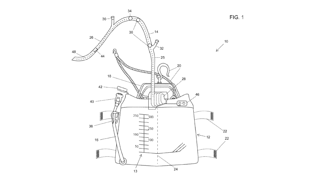
[0013] FIG. 1 is a
nonlimiting schematic representation of a urinary collection
system suitable for use in the present invention.
[0014] FIG. 2
schematically represents a second nonlimiting embodiment of a
collection bag suitable for use with the urinary collection system of FIG. 1.
[0015] FIG. 3
schematically represents the collection bag of FIG. 2 secured to
a patient's leg with a sleeve in accordance with a nonlimiting aspect of the
invention.
[0016] FIGS. 4 and
5 schematically represent a carrying case for use with the
- 5 -
CA 02999121 2018-03-16
WO 2017/049255
PCT/US2016/052388
collection bag of FIG. 2 depicted in closed and open positions, respectively,
in
accordance with a nonlimiting aspect of the invention.
DETAILED DESCRIPTION OF THE INVENTION
[0017] In part,
the present invention was prompted by research reported in
United States Patent No. 6,858,021 to Washington, which evidenced that the
instillation of a weak acidic irrigation solution into a urinary collection
system is
capable of significantly reducing the type and number of certain kinds of
microorganisms in urinary collection systems that use catheter collection
bags,
thereby reducing the incidence of urinary tract infections in patients having
indwelling catheters. The present invention offers additional features for
urinary
collection systems that enable periodic catheter irrigation. A
nonlimiting
embodiment of such a urinary collection system 10 shown in FIG. 1 and
nonlimiting
embodiments of collection bags (receptacles) 12 and 112 shown in FIG. 1
through
3 allow for the convenient instillation of an irrigation solution (preferably
a sterile
acetic acid solution, e.g., distilled acetic vinegar, or other antimicrobial
agent), as
well as decreased cross-contamination during changing of the collection
receptacle
(bag). To facilitate the description provided below of the embodiments
represented
in the drawings, relative terms, including but not limited to, "vertical,"
"horizontal,"
"lateral," "front," "rear," "side," "forward," "rearward," "upper," "lower,"
"above,"
"below," "right," "left," etc., may be used in reference to the orientations
of the
collection bags 12 and 112 during their use by a patient as represented in the
drawings, and therefore are relative terms that indicate the construction and
use of
the invention and therefore help to define the scope of the invention.
[0018] The
nonlimiting embodiment of the urinary collection system 10
schematically represented in the FIG. 1 shows the collection bag 12 thereof
- 6 -
CA 02999121 2018-03-16
WO 2017/049255
PCT/US2016/052388
equipped with a continuous tube 14 through which urine flows into the bag 12
from
the bladder of an individual (hereinafter, "patient"), and a drain tube 16 for
emptying
urine collected in the bag 12. The continuous tube 14 is preferably formed of
a soft,
flexible and antimicrobial material of any suitable type known in the art. The
drain
tube 16 is not required to be antimicrobial, and may be formed of a soft and
flexible
material such as rubber, polyurethane, silicone, etc. The collection bag 12
may be
made of a soft antimicrobial vinyl and preferably has a capacity sufficient
for the
intended patient. A removable handle 18 is shown as being provided for
carrying
the bag 12. The system 10 is further equipped with one or more connectors 20
that
permit the collection bag 12 to be mounted to a fixed surface, such as a bed,
in any
suitable manner, or secured to the patient, for example, to the patient's leg
in any
suitable manner. For purposes of the latter, the bag 12 is represented as
being
equipped with leg straps 22 by which the bag 12 can be secured around a
patient's
leg. The interior of the bag 12 is equipped with a "zip-lock" or other
reversible
separator 24 that facilitates placement of the bag 12 around the leg by
creating a
vertical hinge at which the bag 12 is able to bend at or near its midsection.
The bag
12 may include markings 13 thereon, for example, for use in measuring a volume
of urine contained in the bag 12.
[0019] The
continuous tube 14 generally comprises a portion identified as a
drainage tube 25 and a portion identified as a Foley catheter 26, though other
types
of indwelling urinary catheters are also within the scope of the invention.
The
drainage tube 25 is disposed between the catheter 26 and the collection bag
12.
The continuous tube 14 is represented as further comprising a portion
identified as
an extendable/retractable tubing 28 disposed between the drainage tube 25 and
the
collection bag 12 that enables the continuous tube 14 to be extended or
retracted
as may be desired for the convenience or comfort of the patient. The
continuous
tube 14 is preferably an integrally-formed one-piece component. The lack of
any
- 7 -
CA 02999121 2018-03-16
WO 2017/049255
PCT/US2016/052388
separation between the catheter 26, drainage tube 25, and
extendable/retractable
tubing 28 reduces the number of extraneous sources of contamination and
infection
within the system 10.
[0020] The
continuous tube 14 is also represented as comprising various ports,
in particular, an inflation port 30 that can be used to inflate a balloon (not
shown)
commonly associated with Foley catheters, and an irrigation port 32 for
instilling the
irrigation solution at the drainage tube 25 of the continuous tube 14. A urine
collection port 34 is provided that permits the withdrawal of urine from the
continuous tube 14 (as well as instillation of fluids), and one or more turn
valves 36
are provided that may be used to prevent reflux of the irrigation solution
into the
patient's bladder, perform diagnostic investigations, and/or use for other
purposes
that may entail fluidically isolating the catheter 26 from the drainage tube
25 and/or
collection bag 12.
[0021] The drain
tube 16 includes a one-way turn valve 38 (or other suitable
closure), a retractable drain spigot bell 40, and a cap 42. The drain spigot
bell 40
preferably includes a viscus chlorine gel to inhibit bacterial growth when
emptying
the bag 12, and the turn valve 38 prevents back flow of urine into the bag 12.
[0022] The
catheter portion 26 of the continuous tube 14 preferably includes a
sensing device in the form of a urine analyzer 44 adapted to perform one or
more
chemical measurements on urine as it flows through the continuous tube 14. The
urine analyzer 44 is preferably hypo-allergic, nonhazardous to humans, and
resistant to deterioration and biodegradation within the bio-environment in
which it
operates. Such a urine analyzer 44 may be a microfluidic system fabricated on
a
silicon semiconductor chip and specifically adapted for biomedical analysis,
commonly referred to as a laboratory on a chip (lab-on-a-chip). A nonlimiting
- 8 -
CWCAS-497
example of such a device is disclosed in a paper published online and entitled
"A
Lab-on-a-Chip for Biological Fluids Analysis," available from Graca Minas
through the ResearchGate website, www.researchgate.net. The urine analyzer
44 is preferably configured to measure and/or detect levels of one or more of
nitrates, urobilinogen, proteins, glucose, pH, hemoglobin, blood, volume,
specific
gravity, ketones, bilirubin, bacteria, and yeast.
[0023] The urine analyzer 44 preferably interfaces with a diagnostic unit
46 that
performs quantitative and/or qualitative analysis of the data relating to the
composition of the urine sensed with the urine analyzer 44. The urine analyzer
44
may wirelessly communicate with the diagnostic unit 46, allowing the
diagnostic unit
46 to be located anywhere on the collection bag (for example, as shown in FIG.
1),
or remotely located from the collection bag. For this purpose, FIG. 1
schematically
represents the catheter 26 as incorporating a conductor 48 that serves as an
antenna for wirelessly transmitting data from the urine analyzer 44 to the
diagnostic
unit 46. In some embodiments, the function of the antenna can be performed
with
a radiopaque strip of a type commonly provided in catheters to promote their
visibility under X-ray examination, in which case the radiopaque strip may be
formed
of or contain an electrically-conductive radiocontrast material (nonlimiting
examples
include titanium and tungsten) and is electrically connected to the output of
the urine
analyzer 44.
[0024] The diagnostic unit 46 may include any components suitable for
communicating with the urine analyzer 44 and performing the desired analysis,
including but not limited to a microprocessor, solid-state memory, and a
replaceable
and/or rechargeable battery. The diagnostic unit 46 may include a visual
indicator,
screen, or other means for communicating results of the quantitative and/or
qualitative analysis of the data relating to the composition of the urine, as
well as
- 9 -
CA 2999121 2019-07-02
CA 02999121 2018-03-16
WO 2017/049255
PCT/US2016/052388
push-buttons or the like for direct user interfacing. As a nonlimiting
example, the
diagnostic unit 46 may be configured to enable the patient to wirelessly
access the
results of the quantitative and/or qualitative analysis from a personal
computer,
website, mobile phone, or other means. Measurements performed on the urine and
the quantitative and/or qualitative analysis thereof may be performed on
demand,
periodically, or continuously in order to monitor the health of the patient.
The urine
collection port 34 can be used to withdraw urine for the purpose of verifying
results
obtained with the urine analyzer 44.
[0025] FIGS. 2 and
3 represent the collection bag 112 and components thereof
as another embodiment suitable for use in place of the bag 12 represented in
the
system 10 of FIG. 1. In FIGS. 2 and 3, consistent reference numbers are used
to
identify the same or functionally equivalent elements, but with a numerical
prefix (1,
2, or 3, etc.) added to distinguish the particular embodiment from the
embodiment
of FIG. 1. Other aspects of the bag 112 and its interaction with other
components
of the system 10 not discussed in any detail can be, in terms of structure,
function,
materials, etc., essentially as was described for the first embodiment.
[0026] FIG. 2
schematically represents the collection bag 112 as having an inlet
115 connected to a continuous tube 114 through which urine flows from the
bladder
of a patient and collects in the bag 112. FIG. 2 also schematically represents
a
drain tube 116 connected to an outlet 117 of the bag 112 for emptying urine
111 that
has been collected in the bag 112. The continuous tube 114 may include some or
all of the features discussed in regards to the continuous tube 14 of FIG. 1.
Similar
to the drain tube 16 of FIG. 1, the drain tube 116 preferably includes a one-
way turn
valve 138 (or other suitable closure) and a drain spigot 140. While not in
use, the
drain spigot 140 may be removably stowed in an anti-bacterial pocket 152.
-10-
CA 02999121 2018-03-16
WO 2017/049255
PCT/US2016/052388
[0027] The
interior of the bag 112 is equipped with multiple separators 124 along
which the bag 112 is able to bend. The separators 124 effectively form pivot
joints
or hinges of the bag 112, and may be arranged in a grid such that bending of
the
bag 112 is promoted in multiple directions at multiple locations. For example,
in the
embodiment represented in FIG. 2, the separators 24 of the bag 112 define a
grid
that enables the bag 112 to bend along two vertical hinges and two horizontal
hinges (relative to the orientation in FIG. 2) and effectively create nine
fluidically
connected volumes or sections within the bag 112. The bag 112 may include
markings 113 thereon, for example, for use in measuring the volume of urine
111
contained in the bag 112.
[0028] The bag 112
includes a sensing device in the form of a urine analyzer 144
adapted to perform one or more chemical measurements on urine as it flows
through the continuous tube 114 and into the bag 114. As such, the urine
analyzer
144 is represented as being located at the inlet 115 or directly above the
inlet 115,
and in-line with the flow of the incoming urine from the continuous tube 114.
The
urine analyzer 144 may be functionally equivalent to the urine analyzer 44 of
FIG.
1, and may interface, either directly or wirelessly, with a diagnostic unit
146 that
performs quantitative and/or qualitative analysis of the data relating to the
composition of the urine sensed with the urine analyzer 144. According to one
nonlimiting aspect of the bag 112, as represented in FIG. 2, the urine
analyzer 144
may be built into the bag 112 and disposable therewith, whereas the diagnostic
unit
146 may be removed prior to disposal of the bag 112. For example, FIG. 2
represents the diagnostic unit 146 as being configured to functionally couple
to the
urine analyzer 144 via electrodes 145 located on the bag 112.
[0029] The bag 112
is represented as being equipped with tabs 121 by which the
bag 112 can be secured to a fixed surface in any suitable manner, or secured
to a
-11 -
CWCAS-497
patient, for example, to the patient's leg in any suitable manner. For
example, FIG.
2 represents the tabs 121 as including slots formed therein that are
configured to
accept fastening devices for securing the bag 112 to another object. As a
nonlimiting example, FIG. 3 represents the slots as accepting fasteners 154
for
removably securing the bag 112 to a sleeve 150 worn on a patient's leg 100. In
this
nonlimiting embodiment, the fasteners 154 (represented as buttons) are located
on
the sleeve 150 and inserted into the slots of the tabs 121, which are located
at four
corners of the bag 112 in order to hold the bag 112 against the sleeve 150. As
represented, the hinges in the bag 112 defined by the separators 124 promote
the
ability of the bag 112 to conform to the shape of the patient's leg 100,
thereby
promoting comfort and reducing the profile of the bag 112. The sleeve 150 may
be
formed of any material, preferably washable, moisture wicking, and/or
breathable
fabrics of the types commonly used for sporting or medical applications.
[0030] FIGS. 4 and
5 schematically represent a nonlimiting embodiment of a
carrying case 180 configured to hold the bag 112 during transport. The case
180
has an interior cavity closable by a cover 188. An interior surface 186 of the
cavity
comprises protrusions 198 (FIG. 5) configured to be inserted into the slots in
the
tabs 121 of the bag 112 and thereby secure the bag 112 against the surface 186
within the case 180. The cover 188 may be used to conceal the bag 112 within
the
cavity during use of the case 180 as represented in FIG. 5, which further
represents
the cover 188 as being secured in a closed position with a flap 190 and
fastener
192. The cover 188 is represented as including a hole 196 at its upper end to
allow
the continuous tube 114 to be routed from the interior cavity of the bag 112
to its
exterior. In addition, a hole 194 is provided at the upper end of the cover
188 to
provide access to the urine analyzer 144, for example, to visually observe a
visual
indicator (such as a light) or a display screen (not shown) on the analyzer
144. The
case 180 may include straps 182 and/or a handle 184 in order to promote
- 12 -
CA 2999121 2019-07-02
CA 02999121 2018-03-16
WO 2017/049255
PCT/US2016/052388
convenient transportation of the case 180 and the bag 112 stowed therein.
[0031] The urinary
collection system 10 represented in the drawings has the
potential for reducing catheter-associated urinary tract infections and the
nosocomial
spread of bacteria. In use, a sterile acetic acid solution can be installed
into the
collection bag 12 or 112 via the continuous tube 14 or 114, after which the
solution
can be dispersed in the collection bag 12 or 112 and then drained from the bag
12
or 112 via the drain tube 16 or 116. Afterwards, use of the system 10 by a
catheterized patient can resume by allowing urine to flow from the patient
through
the continuous tube 14 or 114 and into the collection bag 12 or 112. To
provide
certain benefits believed to be associated with the use of the system 10, an
effective
amount of irrigation solution is generally that which will coat at least the
entire
interior of the collection bag 12 or 112. As such, the amount of solution
necessary
to reduce the incidence of bacterial growth and its subsequent propagation
into the
bladder will depend in part of the capacity of the bag 12 or 112. However, it
is
believed that a standard instillation dose of about thirty to about fifty
milliliters is
sufficient to lower bacterial colony counts below pathogenic levels, with the
use of
lower and higher doses being foreseeable. Using such solutions to reduce
bacterial
colony count within a collection bag, that is, decreasing a patient's risk in
polymicrobial bacterial propagation within the urinary collection system 10,
can
reduce the incidence of catheter-acquired bladder bacteriuria.
[0032] While the
invention has been described in terms of specific embodiments,
it is apparent that other forms could be adopted by one skilled in the art.
For
example, the physical configuration of the system 10 or its components could
differ
from that shown, and materials and processes/methods other than those noted
could be used. In addition, the invention encompasses additional embodiments
in
which one or more features or aspects of different disclosed embodiments may
be
-13-
CA 02999121 2018-03-16
WO 2017/049255
PCT/US2016/052388
combined. Therefore, the scope of the invention is to be limited only by the
following
claims.
-14-