Note: Descriptions are shown in the official language in which they were submitted.
CA 02999243 2018-03-20
WO 2017/052367 PCT/NL2016/050649
1
DEVICE FOR CONVERTING WIND ENERGY TO AT LEAST MECHANICAL ENERGY
The invention relates to a device for converting wind energy to at least
mechaniCal energy,
comprising a rotor with a number of rotor blades drivable rotatably about a
rotation axis by wind
and a duct disposed therearound, wherein a central axis of the duct
substantially coincides with the
rotation axis of the rotor.
Such a device for converting wind energy to at least mechanical energy is per
se known,
and is also referred to as a wind turbine or windmill. The invention can
relate particularly to a
relatively small wind turbine, also referred to as a microturbine or urban
wind turbine, which wind
turbine can be set up in an urban environment, and in particular optionally on
a building. The
invention can relate more particularly to a so-called horizontal wind turbine,
wherein in use of the
wind turbine the rotation axis of the rotor and the central axis of the duct
are disposed substantially
horizontally.
It is an object of the invention to improve the per se known device of the
type stated in the
preamble. A particular object of the invention can be to increase the
efficiency of the per se known
device.
This object is achieved with a device of the type stated in the preamble which
is
characterized according to the invention by guide means disposed upstream of
the rotor for guiding
the wind in a substantially helical movement round the central axis during use
of the device such
that the wind is supplied in the substantially helical movement round the
central axis to the rotor.
By supplying the wind airflow in said helical movement round the central axis
to the rotor
the airflow is supplied substantially to an outer peripheral zone of the
rotor, whereby the pressure
increases at the outer peripheral zone of the rotor and decreases in the area
of the rotation axis.
This provides for an increased torque on the rotor blades of the rotor,
whereby the efficiency of the
rotor can increase.
Another effect of said helical movement of the airflow round the central axis
is that the
resistance of the airflow in the duct can hereby decrease relative to a non-
helical airflow flowing
through a duct.
It is noted that the guide means are disposed particularly in the duct, more
particularly just
in front of the rotor as seen in flow direction.
It is further noted that the duct can comprise any suitable cross-sectional
form. The duct
here preferably has a circular cross-sectional form at least in the area of
the rotor so that the part of
the duct where the rotor is disposed is substantially cylindrical. A wind
inlet opening and/or a wind
outlet opening of the duct can also have a substantially circular cross-
section. In that case the duct
preferably has a circular cross-sectional form at any random location along
its length. The wind
inlet opening and/or the wind outlet opening can alternatively have any other
suitable cross-
CA 02999243 2018-03-20
WO 2017/052367 PCUNL2016/050649
2
sectional form, such as for instance oval. In the case of such a non-circular
cross-sectional form of
the wind inlet opening and/or the wind outlet opening the duct preferably
transposes gradually to
the circular cross-sectional form in the area of the rotor.
Said substantially helical movement can extend here in substantially circular
manner round
the central axis, optionally with increasing cross-sectional dimension or
diameter as will be further
elucidated below, but also in a non-circular manner, such as for instance
ovally. The form of the
helical movement round the central axis can be substantially adapted here to
the cross-sectional
form of the duct.
In an embodiment of the device according to the invention the guide means
comprise a
number of stator blades disposed in the duct, which stator blades extend
radially outward from the
central axis.
The intended effect of guiding the wind in said substantially helical movement
round the
central axis can take place effectively by selecting a suitable geometry
and/or disposition of the
stator blades.
In another embodiment of the device according to the invention the stator
blades have a
main plane extending radially from the central axis, which main plane is
disposed at an oblique
angle relative to the central axis.
The stator blades disposed obliquely relative to the central axis guide the
airflow in the
oblique direction defined by the stator blades relative to the central axis,
whereby the airflow is
guided in said helical movement round the central axis. The oblique angle of
the stator blades here
substantially determines the angle of the helical airflow to the central axis.
The oblique angle of the stator blades, and thereby the helical airflow
relative to the central
axis, is preferably selected subject to the velocity of the airflow in the
duct and/or the rotation
speed of the rotor. Since this velocity and/or the rotation speed can vary, it
is advantageous for the
stator blades to be adjustable for the purpose of adjusting the oblique angle.
In practical manner the stator blades are automatically adjustable subject to
the velocity of
the airflow in the duct and/or the rotation speed of the rotor. The device can
for this purpose be
provided with measuring means for measuring the velocity of the airflow in the
duct and/or the
rotation speed of the rotor, wherein the device is configured to adjust the
oblique angle of the stator
blades relative to the central axis subject to the measured velocity and/or
rotation speed.
In yet another embodiment of the device according to the invention each stator
blade is
connected to the duct via a connecting shaft extending radially relative to
the central axis such that
the stator blade is pivotable about or with the connecting shaft for the
purpose of adjusting the
oblique angle of the stator blade relative to the central axis.
The device can alternatively comprise a central shaft coinciding with the
central axis,
wherein each stator blade is connected to the central shaft via a connecting
shaft extending radially
CA 02999243 2018-03-20
WO 2017/052367
PCT/NL2016/050649
3
relative to the central shaft such that the stator blade is pivotable about or
with the connecting shaft
for the purpose of adjusting the oblique angle of the stator blade relative to
the central axis.
The connecting shaft can optionally be connected to both the duct and the
central shaft.
In practical manner each stator blade is connected fixedly to a respective
connecting shaft
so that the respective stator blade is adjusted to a chosen angle with the
central shaft (axis) by
pivoting the connecting shaft.
The oblique angle can for instance lie between or he adjustable between 10-80
, preferably
between 20-60 .
In yet another embodiment of the device according to the invention each stator
blade has at
least one through-opening arranged therein.
The at least one opening limits the formation of air vortices behind the
stator blade.
Alternatively or additionally the at least one opening reduces the frontal
surface area of the stator
blade.
The stator blade can for instance be provided with a relatively small number,
for instance
one, of relatively large openings. The stator blade can alternatively be
provided with a relatively
large number of relatively small openings, for instance three or four, up to
for instance a maximum
of ten. The number of openings can hereby be for instance between one and ten.
It is noted that the
number of openings is not limited hereto. Each stator blade can comprise any
suitable number of
openings.
In practical manner the surface area of the at least one opening, or the
combined surface
area of a plurality of openings, is a minimum of 5% and a maximum of 60% of
the surface area of
a or the main plane of the stator blade.
The at least one opening can have any suitable and/or desired shape such as,
though not
only, circular. The minimal cross-sectional dimension, for instance the
diameter in the case of a
circular opening, is preferably greater than a quarter of the thickness of the
stator blade.
The at least one opening can consist of any suitable and/or desired
embodiment, such as,
though not only, a hole or a cutaway.
In yet another embodiment of the device according to the invention each stator
blade is
provided with a number of upright ribs extending from a pressure side thereof,
which ribs extend
from a wind entry side of the blade to a wind exit side of the stator blade,
wherein as seen in radial
direction the ribs extend obliquely over said side such that on the wind exit
side each rib is located
at a greater radial distance from the central axis than on the wind entry
side.
The ribs support the change in the flow direction of the airflow to said
helical movement.
The airflow is moreover guided outward in radial direction so that the airflow
is supplied to the
outer peripheral zone of the rotor, which rotor has an increased efficiency
because of the thereby
increased torque.
CA 02999243 2018-03-20
WO 2017/052367 PCT/NL2016/050649
4
The ribs can particularly extend radially outward with a determined curvature
over said
side such that on the wind exit side each rib is located at said greater
radial distance from the
central axis than on the wind entry side.
The ribs can have a height lying between 0.1% and 25% of the maximum height of
the
stator blade.
The height of the stator blade is defined here in the radial direction,
particularly from a
position close to the central axis to a position close to the duct.
In yet another embodiment of the device according to the invention each stator
blade
comprises a wind entry side and a wind exit side, wherein the stator blade is
provided on its wind
exit side with an end edge, the second derivative of which changes sign more
than once.
Such an end edge of the device according to this embodiment of the invention
provides the
advantage that the formation of air vortices behind the outflow edge is
limited, whereby the airflow
over the blades can be improved.
Applicant has found that a substantially sine-shaped end edge is particularly
effective in
limiting the formation of air vortices behind the outflow edge.
It is however also possible for the end edge to be substantially block tooth-
shaped or
sawtooth-shaped, these shapes likewise being able to at least partially
provide the intended effect.
As further alternative the end edge can be provided with a number of elements
which
extend in a main plane of the stator blade and which each take the form of a
parabola or a part of a
circle. These shapes can also at least partially provide the intended effect.
In yet another alternative the end edge can be provided with a number of
elements which
extend in a main plane of the stator blade and which each take a substantially
feather-like form.
This shape can also at least partially provide the intended effect.
The end edge can optionally have a thickness varying along its length.
In another embodiment of the device according to the invention each rotor
blade comprises
a wind entry side and a wind exit side and is provided on its wind entry side
with a front end edge,
which front end edge comprises an inner end, which is disposed close to the
rotation axis, and an
outer end and wherein a main line of the front end edge between the inner end
and the outer end
takes a substantially curved form.
The form of the front end edge of the road blades is adapted here to the
stator blades in
order to obtain the greatest possible torque on the rotor provided by the
airflow.
An angle of the main line close to the inner end of the front end edge
relative to a straight
line between the inner end and the outer end can here be greater than -450 and
smaller than 45 ,
preferably greater than -35 and smaller than 35 .
An angle of the main line close to the outer end of the front end edge
relative to a or the
straight line between the inner end and the outer end can here be greater than
-60 and smaller than
CA 02999243 2018-03-20
WO 2017/052367 PCT/NL2016/050649
60 .
The rotor blades can be disposed at an angle to the rotation axis, wherein the
angle is
greater than 35 and smaller than 75 , preferably greater than 40 and smaller
than 65 .
The number of rotor blades which the rotor comprises is preferably equal to
the number of
5 stator blades, this number being for instance between two and eight.
In yet another embodiment of the device according to the invention at least
the inner side
of the duct from the inlet opening to at least a position close to the rotor
has the form of a Venturi
narrowing in flow direction.
An advantage of the Venturi form is that the velocity of the airflow in the
direction of the
rotor is accelerated, whereby even at relatively low wind force the device is
able to generate energy
through driving of the rotor.
The Venturi form can be particularly advantageous in combination with said
guide means,
because the airflow can hereby also be guided upstream of the duct in said
helical movement round
the central axis. Because the helical movement has a radially outward
component, the helical
movement of the airflow upstream of the duct will have a greater cross-
sectional dimension, for
instance a larger diameter in the case of a wind inlet opening with a circular
cross-sectional form,
than the duct itself. The frontal surface area of wind from which the device
can extract energy is
hereby effectively enlarged relative to the physical size of the device,
particularly relative to the
inflow surface area of the duct.
In yet another embodiment of the device according to the invention the duct is
provided on
its outer side with at least one wind capture element extending radially
outward, which at least one
wind capture element is provided with at least one channel extending to the
inner side of the duct.
An advantage of the wind capture elements is that wind flowing on the outer
side of the
duct is captured and fed to the inner side of the duct so that the amount of
wind supplied to the
rotor can increase and/or the possible Venturi effect can be enhanced.
The wind capture elements, particularly in combination with the above
elucidated stator
blades, provide the advantage that the efficiency of the wind turbine does not
decrease, or at least
does so to lesser extent, in turbulent wind flows, as can be the case with the
per se known wind
turbines. This is particularly advantageous in a built-up area where many
turbulent flows can
occur. According to such an embodiment comprising the wind capture elements
and the stator
blades, the wind turbine can hereby stand on a relatively low foot.
The at least one channel can preferably extend along at least a part of its
length in flow
direction through the duct in substantially helical form round the central
axis for the purpose of
supplying the wind in said substantially helical movement to the inner side of
the duct.
The wind capture elements with channels can in this embodiment be the guide
means for
guiding the wind in said substantially helical movement round the central
axis.
CA 02999243 2018-03-20
WO 2017/052367 PCT/NL2016/050649
6
Wind capture elements with channels can in this embodiment alternatively be
provided in
addition to other guide means for guiding the wind in said substantially
helical movement, so that
the effect of the helical movement is reinforced.
In practical manner said part of the channel debouches with an outlet opening
on the inner
surface of the duct.
The channel, in particular the part thereof debouching on the inner surface,
extends for
instance at an angle greater than 0 and smaller than 120 to the central
axis.
A dimension of the cross-sectional surface area of the at least one channel
can decrease
along at least a part of its length in downstream direction.
The flow speed of the air flow in the channel is hereby accelerated.
Three to six wind capture elements can for instance be provided which each
extend over a
part of the outer periphery of the duct and are optionally arranged
distributed equally over the outer
periphery.
The height of the or each wind capture element can for instance be 0.05 x -
0.2 x the
maximum cross-sectional dimension of the duct.
The width of the or each wind capture element can for instance be 1 x - 10 x
the height of
the or each wind capture element.
In yet another embodiment of the device according to the invention the stator
blades are
provided with a structure, which structure has a pattern of recesses for
receiving substantially
stationary air.
An advantage of the pattern of recesses according to the invention, which
serve to receive
substantially stationary air, is that the surface of the stator blades in
contact with the airflow
flowing in the duct consists partially of the stationary air present in the
recesses. For the part where
the airflow is in contact with the stationary air present in the recesses air-
to-air friction will occur,
which provides for a lower friction than the parts where the airflow is in
contact with the stator
blades. The efficiency of the device can increase as a result of the reduction
in the air friction of the
airflow.
According to the invention the structure is characterized by one of the
following features
or a random combination thereof:
- a depth of each recess is between 0.1 x - 2 x the length of each recess;
- a width of each recess is between 0.8 x - 3.5 x the length of each
recess;
- the recesses have an oval shape, a longitudinal axis of which is disposed at
an angle
relative to the central axis, wherein the angle lies for instance between 0
and 45 ;
- the peripheral wall of each recess extends at an angle to the inner surface
of the duct,
wherein the angle lies for instance between 90 and 100 ;
- the peripheral wall of each recess is connected at a rounded angle to the
bottom of each
CA 02999243 2018-03-20
WO 2017/052367
PCT/NL2016/050649
recess, wherein the rounded angle has for instant= a radius of between Ox-Ix
the length of each
recess;
- the recesses are disposed adjacently of each other in a number of
substantially straight
lines, wherein the straight line extends at an angle relative to the central
axis, wherein the angle lies
for instance between 00 and 900, wherein a centre-to-centre distance between
two recesses
disposed adjacently of each other in one line lies for instance between 1 x -4
x the width of each
recess, and wherein the recesses of two mutually adjacently disposed lines of
recesses are for
instance arranged offset relative to each other, wherein the offsetting is for
instance greater than 0
x the length of each recess and a maximum of 2 x the length of each recess.
The invention will be further elucidated with reference to the figures shown
in a drawing,
in which
- figures 1A-ID show schematically the wind turbine according to a first
embodiment of
the invention, wherein figure IA is a perspective view from a wind inlet side,
figure 1B is a side
view, figure IC is a perspective view from a wind outlet side, and figure ID
is a longitudinal
vertical cross-section;
- figure 2 shows schematically a perspective view of rotor and guide blades
disposed in a
duct of the wind turbine of figure I;
- figures 34 and 313 show schematically in detail the valves on the wind
outlet opening,
wherein figure 3A shows the valves in an open state and figure 3B shows the
valves in a closing
state;
- figures 4A-4C show schematically a nanostructure which can be arranged on a
number of
surfaces of the wind turbine, wherein figure 4A is a top view of the
ranostructure, figure 411 shows
a detail of figure 4A and figure 4C shows a cross-section through the
nanostructure.
- figures 5A-5EG show schematically a rotor of the wind turbine of figure 1,
wherein
figure 5A is a perspective front view, figure 5B is a front view, figure 5C is
a section in the
longitudinal direction of the rotor of figure 513; figure 51) shows a pressure
side of a rotor blade
and figure SE is a rear view of the rotor blade; and
- figures 64 and 673 show schematically the wind turbine according to a second
embodiment of the invention, wherein figure 6A is a perspective view from a
wind inlet side and
figure 613 is a front view.
The various aspects of the invention will be elucidated with reference to the
figures. The
same elements will be designated here with the same reference numerals. The
different aspects of
the invention can be applied individually or in any random combination.
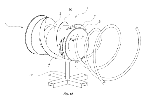
Figures 1A-1D show a wind turbine 1 according to a first embodiment of the
invention.
Wind turbine 1 comprises a duct 2 with a central axis 3. A rotor 4 is disposed
in duct 2, wherein
the central axis 3 of duct 2 substantially coincides with a rotation axis of
rotor 4. Duct 2 has a wind
RECTIFIED SHEET (RULE 91) ISA/EP
CA 02999243 2018-03-20
WO 2017/052367 PCT/NL2016/050649
8
inlet opening 5 and a wind outlet opening 6. In this first embodiment wind
inlet opening 5 and
wind outlet opening 6 are circular.
According to an aspect of the invention, duct 2 is provided on its outer side
close to wind
inlet opening 5 with a number of wind capture elements 7, in this example
three, extending radially
outward. Each wind capture element 7 is provided with a channel 8 extending to
the inner side of
duct 2. The three wind capture elements 7 are arranged distributed at an equal
mutual angular
distance over the outer surface of duct 2. Each channel 8 extends over
substantially its full length
in helical form in flow direction round the central axis through duct 2, and
debouches with an
outlet opening 9 on the inner surface of duct 2. Wind capture elements 7
capture wind flowing on
the outer side of duct 2 and feed this wind in helical form to the inner
surface of duct 2 via outlet
openings 9.
According to another aspect of the invention, see also figure 2, wind turbine
2 comprises a
number of stator blades 10, in this example six, which are disposed upstream
of rotor 4 in duct 2
and which extend radially outward from the central axis 3. Stator blades 10
have a main plane
which extends radially from central axis 3 and which is disposed at an oblique
angle relative to
central axis 3. Because of the oblique angle of the main plane of stator
blades 10 the wind flow
flowing in duct 2 is guided in an oblique direction relative to central axis 3
so that the wind flow is
guided in a substantially helical movement round the central axis 3. Each
stator blade 10, in
particular the main plane thereof, is provided with a number of upright ribs
11, in this example
three. The upright ribs 11 extend from the pressure side of each stator blade
10 from an upstream
wind entry side of blade 10 to a downstream wind exit side of stator blade 10.
Ribs 11 extend
obliquely outward as seen in radial direction over the wind guiding surface so
that on the wind exit
side each rib 11 is located at a greater radial distance from the central axis
than on the wind entry
side. The ribs support the change in the flow direction of the airflow to said
helical movement
round central axis 3. The desired angle of the helical movement of the wind
round central axis 3 is
preferably adjustable. Stator blades 10 are connected for this purpose to a
connecting shaft 12
extending radially from central axis 3, which connecting shafts 12 arc each
connected at their
radial outer end to duct 2. Stator blade 10 is pivotable about or with
connecting shaft 12 for the
purpose of adjusting the oblique angle of stator blade 10 relative to central
axis 3. Each stator blade
10 is provided with a number of openings 13, in this example three. On the
wind exit side each
stator blade 10 is provided with a substantially sine-shaped end edge 14, the
second derivative of
which changes sign more than once.
According to another aspect of the invention, see figure 1D, the inner side of
duct 2 takes
the form, from wind inlet opening 5 up to for instance the location where
connecting shaft 12 is
disposed, of a Venturi narrowing in flow direction. In a part of duct 2 where
rotor 4 is disposed the
inner side of duct 2 is substantially cylindrical. Particularly the
combination of the Venturi form of
CA 02999243 2018-03-20
WO 2017/052367 PCT/NL2016/050649
9
the inner side of duct 2 and the stator blades 10 ensures that the wind flows
in helical form with a
radially outward component upstream of the stator blades 10, so that the
diameter of the wind flow
supplied to wind turbine 2 upstream of wind inlet opening 5 increases in
upstream direction, see
also figure 1A.
According to another aspect of the invention, see figure 1D and figure 2, wind
turbine 2
comprises a number of rear stator blades 20, in this example six, disposed in
duct 2 downstream of
rotor 4 and substantially connecting thereto for guiding the wind away from
rotor 4 in a
substantially downstream direction. Rear stator blades 20 extend radially
outward from central axis
3. Each rear stator blade 20 is provided with a number of upright ribs 21, in
this example three.
Upright ribs 21 extend from the pressure side of each rear stator blade 20
from an upstream wind
entry side of blade 20 to a downstream wind exit side of rear stator blade 20.
Ribs 21 extend
obliquely outward as seen in radial direction with a determined curvature over
the wind guiding
surface so that on the wind exit side each rib 21 is located at a greater
radial distance from central
axis 3 than on the wind entry side. Ribs 21 substantially convert a possible
helical airflow coming
from rotor 4 to a radially outward expanding airflow flowing substantially
parallel to central axis 3.
The angle of rear stator blades 20 to the central axis is preferably
adjustable. Rear stator blades 20
are connected for this purpose to a connecting shaft 22 extending radially
from central axis 3,
which connecting shafts 22 are each connected at their radial outer end to
duct 2. Rear stator blade
is pivotable about or with connecting shaft 22 for the purpose of adjusting
the angle of rear
20 stator blade 20 relative to central axis 3. On the wind exit side each
rear stator blade 20 is provided
with a substantially sine-shaped end edge 24, the second derivative of which
changes sign more
than once. Each rear stator blade 20 has substantially two blade parts 25, 26
disposed at an angle
a4 relative to each other, wherein blade part 25 substantially connects to
rotor 4 and blade part 26
is disposed downstream of blade part 25. Depending on the adjusted angle of
rear stator blade 20,
blade part 25 can extend substantially at an angle to central axis 3 and blade
part 26 can extend
substantially parallel to central axis 3. The angle al between blade parts 25,
26 is in this example
around 130'. Blade part 26 has an increasing height so that the wind is guided
substantially radially
outward, and thereby expands. The increasing height of blade part 26 is
optionally adapted to the
form of the inner side of that part of duct 2 where blade part 26 is disposed,
as will be further
elucidated below.
According to another aspect of the invention, see figure 1D, a part of duct 2
extending
from rotor 4 to wind outlet opening 6 widens in flow direction, particularly
in the form of a
Venturi. Duct 2 widens in Venturi form particularly on both its inner side and
its outer side. Due to
the Venturi form of the outer side of duct 2 the airflow flowing on the outer
side of duct 2 is guided
radially outward to some extent, whereby an underpressure is created in the
area of outlet opening
6. An outlet angle all of wind outlet opening 6 to central axis 3 is in this
example about 60 .
CA 02999243 2018-03-20
WO 2017/052367 PCT/NL2016/050649
As elucidated above with reference to rear stator blades 20 and as shown in
figure 1D and
figure 2, the height of blade part 26 can be adapted here to the inner side of
duct 2 widening in the
form of a Venturi. A tangent of an upper edge 27 of each rear stator blade 20,
and in particular of
blade part 26 thereof, can make an angle a2 with central axis 3 which is
adapted to the inner side of
5 duct 2 widening in the form of a Venturi, and thereby increases in this
example along its length in
downstream direction from about 20 to about 80 .
According to another aspect of the invention, duct 2 has a thickness and/or
form such that
the flow distance of the wind through duct 2 is smaller than the flow distance
round the outer side
of duct 2, and that because of the form the flow direction round the outer
side of duct 2 changes
10 direction at the position of wind outlet opening 6. An underpressure is
hereby created in the area of
outlet opening 6.
According to another aspect of the invention, the diameter of wind outlet
opening 6 of the
duct is greater than an outer diameter of wind inlet opening 5 of duct 2.
According to another aspect of the invention, the outer periphery of duct 2 is
provided with
a helical upright rib 30. This lengthens the flow distance of the wind on the
outer side of duct 2
compared to the flow distance of the wind through the inner side of duct 2,
and it changes the flow
direction round the outer side of duct 2. An underpressure is hereby created
in the area of outlet
opening 6.
According to another aspect of the invention, see also figures 3A, 3B, wind
turbine 1 is
provided in the area of wind outlet opening 6 of duct 2 with a number of
annular elements 40, in
this case two, disposed concentrically with outlet opening 6. Annular elements
40 each have a
different diameter which are both smaller than the diameter of outlet opening
6. Annular elements
40 each comprise a cylindrical peripheral surface which extends obliquely
outward in downstream
direction at an angle to central axis 3. Annular elements 40 are therefore
substantially conically
widening annular elements. Due to the outward tapering form of annular
elements 40 the wind
flowing out of outlet opening 6 is guided radially outward. Arranged on duct 2
extending over the
periphery of outlet opening 6 is a flexible valve 41 which is connected with
one end zone to duct 2.
Arranged on the outer annular element 40 is a flexible valve 41 which extends
over the periphery
thereof and which is connected with one end zone to annular element 40. In
figure 3A valves 41
are shown in their open state, in which they leave outlet opening 6
substantially clear. The wind
flowing out of wind outlet opening 6 moves the valves automatically into this
open state. When the
wind turns and threatens to flow into duct 2 via outlet opening 6, the wind
pushes valves 41
automatically to their closing state as shown in figure 3B. In the closing
state the valve 41
connected to duct 2 lies with its free end zone against the outer annular
element 40, and the valve
connected to the outer annular clement 4.0 lies against the inner annular
element 40 so that valves
41 substantially close at least the peripheral zone of wind outlet opening 6.
Particularly the valve
CA 02999243 2018-03-20
WO 2017/052367 PCT/NL2016/050649
11
41 connected to outlet opening 6 substantially closes the space between outlet
opening 6 and the
outer annular element 40. Particularly the valve 41 connected to outer annular
element 40
substantially closes the space between outer annular element 40 and inner
annular element 40.
Bounding elements in the form of rods 42 extend between the peripheral end
zone of outlet
opening 6 of duct 2 and outer annular element 40 and between outer annular
element 40 and inner
annular element 40. These rods 42 prevent the flexible valves 41 blowing the
valves 41 further
inward from their closing state by the wind threatening to flow into outlet
opening 6. In this
example the inner annular element 40 is not provided with a valve, so that a
central part of outlet
opening 6 cannot be closed. This inner annular element 40 can if desired also
be provided with a
valve so that the central part of outlet opening 6 can be closed and outlet
opening 6 can be
substantially completely closed.
Wind turbine 1 according to the invention can particularly be a relatively
small wind
turbine, also referred to as a microturbine or urban wind turbine, which wind
turbine can be set up
in an urban environment, and in particular optionally on a building. Wind
turbine 2 can for this
purpose comprise a leg 50, using which the wind turbine can be set up. As
shown in the figures,
wind turbine 1 is particularly a so-called horizontal wind turbine, wherein
the rotation axis of the
rotor and the central axis 3 of duct 2 are disposed substantially horizontally
during use of wind
turbine 1.
An inner surface of the duct and/or rotor blades of the rotor is/are provided
with a
structure, which structure has a pattern of recesses for receiving
substantially stationary air.
Figures 4A-4C show a nanostructure 60 which can for instance be arranged on
the inner
surface of duct 2 and/or on stator blades 10 and/or on rear stator blades 20.
Nanostructure 60 has a
pattern of recesses 61 for receiving substantially stationary air. The
dimensions of recesses 61 lie in
the order of magnitude of several gm to several mm. In this example the
dimensions are
substantially oval, but can take any desired form. In this example the length
62 of each recess is
about 4.2 mm. The width 63 of each recess in this example is about 2.3 mm. In
this example the
depth 64 of each recess is about 0.7 mm. The peripheral wall of each recess 61
extends in this
example at an angle a3 to the inner surface of the duct and/or the surface of
stator blade 10 and/or
rear stator blade 20, wherein the angle a8 is in this example about 95 . The
peripheral wall of each
recess 61 is connected in this example at a rounded angle 65 to the bottom of
each recess, wherein
the rounded angle 65 in this example has a radius of about 0.6 mm. In this
example the recesses 61
are disposed adjacently of each other in a number of substantially straight
lines 69, wherein the
straight line extends at an angle a4 relative to the central axis 3, wherein
the angle a4 in this
example is about 41 . In this example a centre-to-centre distance 66 between
two recesses 61
disposed in one line adjacency of each other is about 3.8 mm. In this example
recesses 61 of two
mutually adjacent lines 69 of recesses 61 are disposed offset relative to each
other, wherein the
CA 02999243 2018-03-20
WO 2017/052367 PCT/NL2016/050649
12
offsetting 67 in a direction perpendicularly of the longitudinal direction of
duct 2 is in this example
about 1.1 mm. A centre-to-centre distance 68 between two adjacent recesses 61
of adjacent lines
69 is in this example about 5.2 mm.
Figures 5A-5E show a rotor according to an aspect of the invention. The rotor
comprises a
number of rotor blades 70, in this example six, which are connected with a
peripheral edge to a
rotor body 71 of a generator, see also figure 1D. Rotor 4 is driven rotatingly
by a wind flow
flowing in duct 2, whereby rotor body 71 co-rotates. A stator body 77 of the
generator disposed in
duct 2 is arranged round rotor body 71, see figure 1D. As shown in figure 5C,
rotor blades 70 are
disposed at an angle a5 to rotation axis 3, this angle a5 being about 530 in
this example. As shown
in, among others, figures 5A, 5B and 5D, the rotor blades have a wind entry
side with a front end
edge 72 and a wind exit side with an end edge 73. End edge 73 is substantially
sine-shaped over a
curved main line 74. An angle a6 of main line 74 close to an inner end of end
edge 73, which is
disposed close to the rotation axis coinciding with central axis 3, relative
to a straight line 75
between the inner end and the outer end of end edge 73, which is disposed
close to rotor body 71,
is in this example about 38 . An angle a7 of the main line 74 close to the
outer end of end edge 73
relative to the straight line 75 between the inner end and the outer end is in
this example about 17 .
The front end edge 72 is substantially arcuate. An angle a8 of front end edge
72 close to an inner
end of front end edge 72, which is disposed close to the rotation axis
coinciding with central axis 3,
relative to a straight line 76 between the inner end and the outer end of
front end edge 72, which is
disposed close to rotor body 71, is in this example about 28 . An angle a14 of
front end edge 72
close to the outer end of front end edge 72 relative to the straight line 76
between the inner end and
the outer end is in this example about 48 . As can be seen in, among others,
figures 5C and 5E,
rotor blades 70 are twisted in a direction between an inner end zone and the
peripheral edge
connected to generator body 71, in this example through an angle al5 of about
5 .
Figures 6A and 6B show a wind turbine 1 according to a second embodiment of
the
invention. Only the differences from the wind turbine of figures 1-5 will be
elucidated here, and for
a further specification of figures 6A and 6B reference is made to the figure
description associated
with figures 1-5.
Wind turbine 1 according to the second embodiment of the invention differs
from the wind
turbine according to the first embodiment in that inlet opening 5 and outlet
opening 6 are
substantially oval-shaped instead of circular. Duct 2 transposes gradually
from its oval end zones
or openings 5, 6 to a round cross-sectional form so that the part of duct 2
where rotor 4 is disposed
is substantially cylindrical, just as in the wind turbine according to the
first embodiment.
It is noted that the invention is not limited to the shown embodiments but
also extends to
variants within the scope of the appended claims.
The stated values for dimensions, angles and the like are thus given only by
way of
CA 02999243 2018-03-20
WO 2017/052367 PCT/NL2016/050649
13
example. Applicant has found that said values are particularly suitable, but
the invention is thus not
limited thereto.
It will also be apparent that the form of the inlet opening and/or outlet
opening is not
limited to the shown circular shape or oval shape, but that it can have any
suitable shape. The part
where the rotor is disposed is however preferably of circular cross-section,
and thereby cylindrical,
wherein in the case of a non-circular inlet opening or non-circular outlet
opening a gradual
transition to this cylindrical part will take place.