Note: Descriptions are shown in the official language in which they were submitted.
CA 02999538 2018-03-22
WO 2017/054040 PCT/AU2016/050907
- 1 -
MICROPROJECTION ARRAYS WITH ENHANCED SKIN PENETRATING
PROPERTIES AND METHODS THEREOF
Background of the Invention
[0001] The invention is generally directed to devices and methods for
intradermal delivery of
active agents into the skin, more particularly the invention is directed to
devices and methods
for improving the immunogenicity of vaccine preparations by intradermal
delivery of the
vaccine via a microprojection array in which the parameters for delivery of
the active agents
have been developed to achieve appropriate depth penetration and efficient
delivery of the
active agent.
Description of the Prior Art
[0002] Next-generation healthcare increasingly relies on minimally-invasive
biomedical
devices capable of negotiating skin mechanical properties to mediate
intracutaneous and
transcutaneous tasks like administering therapeutics, extracting diagnostic
biomarkers and
performing surgical procedures. For instance, epidermal and dermal targeted
delivery of
vaccines is a promising candidate for increasing global vaccine coverage, due
to ease of
access as well as unique immunological properties of the skin. Passive
permeation of the
antigen is impractical due to the large molecular size of most antigens,
therefore, the payload
is actively transported to the viable-cell strata by mechanically breaching
through the skin's
outer barriers. This transport is typically achieved by either: 1) high-
pressure jet injectors that
fire the payload in liquid or powder form (microparticles) or 2) penetrator
tips that deposit
payload through a channel in the skin (e.g. intradermal syringe needles and
hollow
microneedles), or that embed the payload in a matrix / coating that dissolves
in the skin
(e.g. dissolvable / coated microneedle and microprojection arrays). Some
studies have
reported improved immune responses compared to standard syringe injection. In
addition, the
mechanisms underlying the low-dose efficacy or increased potency are not yet
fully
understood thereby limiting the potential of cutaneous vaccination.
[0003] Precise penetration to the targeted depth for vaccine uptake by site-
specific cells is of
fundamental importance and relies on negotiating the unique elastic and
failure properties of
the skin which is a multilayer composite 'material'. Despite the many
published mechanical
CA 02999538 2018-03-22
WO 2017/054040 PCT/AU2016/050907
- 2 -
characterization and underlying linear and non-linear elastic models, there is
a paucity of
investigations focusing on skin elastic and failure behavior in mechanical
conditions relevant
for epidermal and dermal delivery of active agents including vaccines. There
are reasons
beyond the skin's intrinsic structural complexity, and inter-species (e.g.
mouse vs human),
inter-individual (ethnicity, gender) and intra-individual (age, body site)
variabilities for this
failure. Firstly, the persistent assumption of skin homogeneity and
isotropicity resulted in
different elastic moduli depending on the loading mode. Secondly, the Young's
moduli
extrapolated from indentations showed a marked inverse dependence with the
probe
diameter. Thirdly, although the extensive literature on skin viscoelasticity
provides solid
evidence of the rate-dependence of skin elasticity, there appear to be no
published
out-of-plane tests where the load was applied at velocities > 1 m s-1 or
strain rates > 1 iLt s-1.
[0004] While underlying linear-elastic and hyperelastic descriptions are
corroborated by
empirical data, skin also lacks established constitutive models of failure.
Skin penetration by
individual needles has typically been described using either: 1) stress-based
failure criteria
extend the traditional yield criteria such that the skin fails when the stress
(typically the von
Mises component) exceeds a threshold strength; as such, this framework does
not account for
the irrecoverable energy dissipated into material damage and, thus, for
example, cannot be
used to predict the depth achieved by penetrators fired at a given velocity;
or 2) energy-based
fracture propagation extends the concept of fracture toughness to ductile
materials, i.e. an
energy per unit area representing the cost to create crack interfaces. This
model, though, does
not specify if an initial notch forms at all (failure initiation), how the
crack propagates (e.g.
direction and speed), and what fraction of the penetrator energy is utilized
in the fracture (as
opposed of being elastically stored or dissipated in viscous or plastic
phenomena). Rather, the
prediction of skin penetration requires a complete description of the spatial
stress-strain
distributions to detect the instant and coordinates of failure initiation, and
the energy
repartition among various reversible and irreversible phenomena.
[0005] Skin out-of-plane mechanical properties of skin at the microscale are
typically
measured ex vivo using indentation (e.g. AFM) at velocities up to ¨100 iLim s-
1 ; however,
vaccines are delivered in vivo across the skin's superficial barriers using
penetrators applied
CA 02999538 2018-03-22
WO 2017/054040 PCT/AU2016/050907
- 3 -
(by hand or impact applicators) at velocities >> mm s-1; strain-rate effects
and subcutaneous
layers play an important mechanical role during skin penetration.
[0006] The limited understanding of skin elastic response to high strain
rates, mechanisms of
failure and fracture, and interaction with multiple penetrators have prevented
the rational
design of epidermal and dermal targeted vaccination devices. Some
microprojection arrays
are silicon chips containing, on one side, thousands of densely-arranged (>>
1,000 cm-2)
microprojections, i.e. solid cone-like structures measuring ¨100 iLim in
length. Notably,
application of vaccine-coated microprojection arrays to mouse skin elicited
immune response
using ¨1/100 of the dose required by intramuscular injection. The precise and
consistent
targeting of specific strata within the skin is important and achieved by
applying the array
against the skin at controlled velocities (-1 m s-1). Therefore, there is a
need for in-depth
understanding of the skin mechanical interaction with microneedles/
microprojections which
would allow the tailoring of an array design and application conditions to
achieve customized
antigen placement and to increase the targeting consistency across patients
and minimize the
penetration energy of the array while controlling skin inflammation,
tolerability and
acceptability.
[0007] The reference in this specification to any prior publication (or
information derived
from it), or to any matter which is known, is not, and should not be taken as
an
acknowledgment or admission or any form of suggestion that the prior
publication (or
information derived from it) or known matter forms part of the common general
knowledge
in the field of endeavour to which this specification relates.
Summary of the Present Invention
[0008] In a broad form the present invention seeks to provide an apparatus for
delivering an
active ingredient into the skin of an animal at a defined depth, the apparatus
including:
a) a microprojection array including a plurality of microprojections having a
density
of at least 2,000 projections per cm2; and,
b) an applicator that drives the microprojection array towards the skin in use
so that
the microprojection array impacts on the skin with a mass-to-velocity ratio of
between 0.0005 g/m/s and 0.1 g/m/s per cm2.
CA 02999538 2018-03-22
WO 2017/054040 PCT/AU2016/050907
- 4 -
[0009] Typically the microprojection array impacts on the skin with a mass-to-
velocity ratio
of at least one of:
a) less than 0.05 g/m/s;
b) less than 0.005 g/m/s; and,
c) between 0.033 g/m/s and 0.0008 g/m/s.
[0010] Typically the microprojection array impacts the skin with a mass
between at least one
of:
a) 0.001 g and 5g;
b) 0.005 g and 2 g; and,
c) 0.02 g and 0.5 g.
[0011] Typically the microprojection array impacts the skin at velocities
between:
a) 5 m/s and 50 m/s;
b) 10 m/s g and 30 m/s; and,
c) 15 m/s and 25 m/s.
[0012] Typically the microprojection array has an area between at least one
of:
a) 16 mm2 and 400 mm2;
b) 36 mm2 and 225 mm2; and,
c) 64 mm2 and 100 mm2.
[0013] Typically the microprojection array has a microprojection density
between 5,000 and
20,000 projections per cm2.
[0014] Typically the microprojections are at least one of:
a) solid;
b) non-porous; and,
c) non-hollow.
[0015] Typically the microprojections are at least one of:
a) tapered;
b) substantially conical;
c) substantially flattened;
CA 02999538 2018-03-22
WO 2017/054040 PCT/AU2016/050907
- 5 -
d) hexagonal; and,
e) octagonal.
[0016] Typically the microprojections have a length of at least one of:
a) more than 100 [tm;
b) more than 200 [tm;
c) less than 1000 [tm;
d) less than 5000 [tm; and,
e) between 200 [tm and 300 [tm.
[0017] Typically the microprojections include:
a) a base having a width of about 5 [tm to about 50 [tm; and,
b) a tip having a width of about 0.5 [tm to about 2 [tm.
[0018] Typically the applicator includes a driver that drives the
microprojection array
towards the skin and wherein the microprojection array is releasably mounted
to the driver so
that the microprojection array is released from the driver prior to the
microprojections
contacting the skin.
[0019] Typically the driver abuts against a stop to thereby release the
microprojection array.
[0020] Typically the stop includes an annular shoulder.
[0021] Typically the applicator includes:
a) a housing containing the driver; and,
b) a substantially tubular spacer that in use is positioned with an open end
in contact
with a surface of the skin to thereby space the housing from the skin, the
stop
being provided proximate the open end of the spacer.
[0022] Typically the driver is urged from a retracted to an extended position
using a biasing
mechanism, and wherein the biasing mechanism and engagement between the driver
and
housing define a driver velocity in use.
[0023] Typically the driver is a piston.
CA 02999538 2018-03-22
WO 2017/054040 PCT/AU2016/050907
- 6 -
[0024] Typically the biasing mechanism includes at least one of:
a) a spring; and,
b) a pneumatic actuator.
[0025] Typically the engagement is frictional engagement between a piston and
piston
chamber within the housing.
[0026] Typically the microprojection array impacts on the skin with a mass-to-
velocity ratio
sufficiently high to effect at least one of:
a) fracture the skin;
b) concentrate mechanical stress in superficial layers of the skin;
c) invoke strain-rate dependent skin stiffening;
d) cause consistent penetration independent of variations in subcutaneous
properties
of the skin;
e) dissipate inertia so as to avoid mechanical stress on body parts underlying
the
skin; and,
f) cause a controlled amount of mechanical stress for immune-enhancing
inflammation.
[0027] Typically at least tips of the microprojections are coated.
[0028] Typically the active ingredient is one or more vaccine antigens.
[0029] In another broad form the present invention seeks to provide a method
of determining
the design of a microprojection array and the velocity for delivering the
microprojection
array to a predetermined range of skin depth comprising calculating the
microprojection array
density, microprojection array area, microprojection array mass and
microprojection velocity
to mass ratio to deliver the microprojection array to the predetermined depth
range.
Brief Description of the Drawings
[0030] An example of the present invention will now be described with
reference to the
accompanying drawings, in which: -
[0031] Figure lA is a schematic drawing of various modes of penetrating the
skin;
CA 02999538 2018-03-22
WO 2017/054040 PCT/AU2016/050907
- 7 -
[0032] Figure 1B is a schematic diagram of design specifications for
individual and arrays of
penetrators (e.g. microneedles / microprojections);
[0033] Figure 1C is a schematic drawing of a mouse ear section and skin layer
thickness;
[0034] Figures 2A-2H are graphical representations of the hyperelastic
properties for the
skin layers (SC = stratum corneum, VE = viable epidermis, dermis) of mouse ear
as a
function of indentation velocity (or peak logarithmic strain rate): Figure 2A
is a plot of
Young's moduli versus the strain rate and velocity for the stratum corneum;
Figure 2B is a
plot of Young's moduli versus the strain rate and velocity for the viable
epidermis; Figure
2C is a plot of Young's moduli versus the strain rate and velocity for the
dermis; Figure 2D
is a plot of the stretch exponent versus the strain rate and velocity for the
stratum corneum;
Figure 2E is a plot of the stretch exponent versus the strain rate and
velocity for the viable
epidermis; Figure 2F is a plot of the stretch exponent versus the strain rate
and velocity for
the dermis; and Figures 2G and 2H are bar diagrams of Young's modulus and
stretch
exponent extrapolated for a probe measuring 1 iLim in diameter indenting the
skin layers in
the velocity range 0.3-10 m s-1 (or strain-rate range 0.3-10 iLt s-1);
[0035] Figures 3A-3D are graphical representations of skin stress and energy
transfers
during the penetration by arrays with different densities applied with equal
energy per
projection (-1/2 * 35 g * (2 m 5-1)2 / 3000): Figure 3A shows VM stress in the
skin during
the penetration of arrays characterized by projection densities of ¨0 proj cm-
2 (infinitely-
spaced projections); Figure 3B shows VM stress in the skin during the
penetration of arrays
characterized by projection densities of 5,000 proj cm-2; Figure 3C shows VM
stress in the
skin during the penetration of arrays characterized by projection densities of
10,000 proj
cm-2; and Figure 3D shows VM stress in the skin during the penetration of
arrays
characterized by projection densities of 20,400 proj cm-2;
[0036] Figure 3E is a diagram of symmetric FE geometry and mesh used to
simulate the
penetration of arrays with > 5,000 proj cm-2, in which the inset shows the
fundamental skin
unit simulated (red) and the planes of symmetry (dashed lines) on a top-view
schematics of
the array;
CA 02999538 2018-03-22
WO 2017/054040 PCT/AU2016/050907
- 8 -
[0037] Figure 3F is a diagram of the fraction of application energy (mean
range) utilized
during the penetration of the ¨0 proj cm-2 array into mouse ear when the tip
reaches the
bottom of the (ventral) dermis as calculated using FEM; the range represent
the variation
between successive time points ( 0.5 iLt s);
[0038] Figure 3G is a diagram of the energy utilized as function of projection
density /
spacing as calculated using FEM;
[0039] Figure 3H is a diagram of the energy fraction (mean sd) transferred
(utilized) to the
ear as measured experimentally from the difference between the impact energies
transmitted
across the backing and the ear + backing to an underlying force sensor.
FEM = finite-element modeling, exp = experiment, inf = infinite;
[0040] Figure 4Ais a schematic of a model used to simulate projection array
penetration into
skin backed by soft tissue; mouse ear layers were modeled using an
axisymmetric FE
geometry with a symmetric boundary; the soft backing material was modeled
using a parallel
spring-damper-mass lumped element;
[0041] Figure 4B is a schematic of the penetration depth resulting from
standard treatment,
i.e. firing the array with an energy of ¨13 mJ (-35 g piston at ¨0.85 m s-1)
on a PDMS-
backed ear (left), and ¨1.3 mJ (-5 g at ¨0.75 m s-1) on ear alone; a +15%
correction factor
was considered to account for the tissue shrinking due to histology treatment;
the mean se
(n = 4) is represented for the experimental groups, whereas the error-bars of
the model group
represent the uncertainty due to FE parameterization as in Figure 4C;
[0042] Figure 4C is a schematic of the sensitivity of the numerical solution
to model
parameterization when the standard treatment condition (35 g, ¨0.85 m s-1) is
used; the bars
indicate the penetration depth resulting varying the model parameters; the
direction of the
depth change when the specific model parameter increases is indicated by the
black curves;
[0043] Figure 4D is a schematic of the numerical and experimental variations
of penetration
depth; the depth range originating from the skin variability has been
represented using the
deviation of the penetration measurements across biological repeats, and
compared to the
widest numerical variability deriving from skin properties, i.e. skin
stiffness;
CA 02999538 2018-03-22
WO 2017/054040 PCT/AU2016/050907
- 9 -
[0044] Figures 5A-5E are plots of numerical (FEM result FE error) and
experimental (exp
mean se) penetration depths as a function of varying application conditions
and array
designs: Figure 5A is a plot of penetration depth versus application velocity;
Figure 5B is a
plot of penetration depth versus piston mass; Figure 5C is a plot of
penetration depth versus
array size; Figure 5D is a plot of penetration depth versus projection
density; Figure 5E is a
plot of penetration depth versus energy/projection, in which the significant
Spearman
correlation (p < 0.0001) found between penetration depth pd and application
energy per
projection U was modeled with power laws pd = A UB , i.e. straight (dotted)
lines in Log-Log
scale, horizontal error-bars represent the standard deviation of the
measurement of
application velocity and number of microprojections on the array following
wafer dicing, and
vertical error-bars were obtained as in Figure 4B;
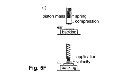
[0045] Figure 5F is a schematic representation of applicator function and main
parameters;
[0046] Figure 6A is a plot of penetration depth versus piston mass under
conditions where 1)
constant spring load; 2) constant energy and 3) constant velocity;
[0047] Figure 6B is a plot of penetration depth versus array size under
conditions where 1)
constant projection density and 2) constant projection number;
[0048] Figure 6C is a plot of penetration depth versus energy/projection
comparing
experimental and FEM for velocity sets, mass sets, array-size-sets and density
sets, in which
the penetration depth escapes the Log-Log linear dependence with application
energy per
projection for very low piston masses and large array sizes; error-bars were
omitted for
clarity;
[0049] Figure 6D is a plot of the percentage of application energy transferred
to the skin
versus piston mass;
[0050] Figure 6E is a plot of the percentage of application energy transferred
to the skin
versus array size;
[0051] Figure 7 is a flowchart of skin failure model, in which the clockwise
flow describes
the approach used in the present application; whereas the anti-clockwise flow
(in grey) shows
CA 02999538 2018-03-22
WO 2017/054040 PCT/AU2016/050907
- 10 -
the simplified implementation used in previous work (VM = von Mises);
[0052] Figure 8 is a plot of force measured by piezoelectric load cell placed
under the
PDMS following ¨2 m s-1 impact of a microprojection array on the PDMS-backed
skin
(PDMS + ear') and flat patch on PDMS backing only (PDMS');
Figure 9 is a plot of force versus compression displacement for impact tests
that were
performed on carbon tab-topped PDMS firing a 5mm-diameter flat-ended piston;
piston mass
and impact velocity (and relative theoretical peak engineering strain rate)
are indicated; the
green datasets have ¨constant kinetic energy; the vertical error-bars indicate
the sd of the
measurements across the different PDMS samples; the horizontal error-bars of
the impact
tests show the uncertainty (sd over the different PDMS samples) of the
compression
displacement measures using the high-speed camera; and the full and dashed
lines show the
stiffness curves selected after PDMS model validation for the brass and
plastic pistons,
respectively; and,
[0053] Figure 10 is a schematic diagram of model geometry of uncoated (full)
and coated
(dashed) microprojection.
Detailed Description of the Preferred Embodiments
[0054] In-depth understanding of skin elastic and rupture behaviors is
important for next-
generation biomedical devices because it enables targeted delivery of
vaccines, as well as
minimally-invasive extraction of diagnostic biomarkers and robotic / haptic
surgery.
Penetration of the skin's superficial barriers and precise targeting of strata
rich in
antigen-presenting cells is critical to elicit potent low-dose immunogenicity.
However, the
paucity of relevant skin mechanical characterization and lack of established
fracture models
has limited the rational design of cutaneous devices. The present invention
exploits
experimental and numerical studies of skin mechanics during dynamic
interaction with
individual and arrays of microscopic penetrators to provide improved methods
and devices
for delivering active agents into the skin. Micro-indentation of individual
strata reveals that
the hyperelastic moduli are dramatically rate-dependent, and allows
extrapolation of the
stiffness properties at velocity regimes (> mm s-1) relevant for dynamically-
actuated
cutaneous devices. These are used to parameterize a layered finite-element
(FE)
CA 02999538 2018-03-22
WO 2017/054040 PCT/AU2016/050907
- 11 -
representation of skin that includes a novel implementation of ductile
failure. Iterative
refinement to match empirical penetration assays yields characteristic
fracture energies (-10
pJ ium-2) significantly lower than previously reported (>> 100 pJ m-2). The
resulting FE
simulations satisfactorily predict the penetration depth of microprojection
arrays across a
diverse range of designs and application conditions, and shows limited
sensitivity to the
parameterization choice. The knowledge and numerical tools developed provide
guidelines to
rationally engineer skin penetrators. Specific array design and application
conditions can be
developed to increase the targeting consistency across patients and minimize
the penetration
energy while controlling skin inflammation, tolerability and acceptability.
[0055] Both experiments and theoretical models were used to develop an
understanding of
the skin's mechanical properties relative to the dynamic penetration of
individual and
multiple microscopic penetrators. These properties are particularly relevant
to the skin
treatment by microneedles / microprojections for vaccine delivery as well as
minimally-
invasive extraction of diagnostic biomarkers. Starting from micro-indentation
experiments on
mouse skin (Figure 1C), the hyperelastic properties of the epidermal and
dermal layers at
high strain-rates (> 1 iLts-1) were derived. These were utilized in
conjunction with finite-
element simulations to further investigate the rate-dependent skin mechanical
response to the
impact of individual and arrays of penetrator tips.
[0056] The complete model schematized in Figure 4A was used to simulate skin
mechanical
interaction with the microprojections in the conditions used for mouse
vaccination
experiment (G. J. P. Fernando, X. F. Chen, T. W. Prow, M. L. Crichton, E. J.
Fairmaid, M. S.
Roberts, I. H. Frazer, L. E. Brown, M. A. F. Kendall, PLoS One 2010, 5,
e10266).
Penetration was studied for varying array designs and application parameters.
For validation,
the calculated penetration depths were compared with experimental measurements
from
histological sections of skin treated with dye-coated arrays according to an
established
protocol (M. L. Crichton, A. Ansaldo, X. F. Chen, T. W. Prow, G. J. P.
Fernando, M. A. F.
Kendall, Biomaterials 2010, 31, 4562).
[0057] Figure 4B shows the simulation and experimental results for a 4x4 mm2
array
containing ¨3000 microprojections spaced of L=70 iLim (i.e. ¨20 kproj cm-2)
applied on
PDMS-backed skin at 0.85 m s-1 with the 35 g piston (i.e. ¨13 mJ), the
'standard treatment'
CA 02999538 2018-03-22
WO 2017/054040 PCT/AU2016/050907
- 12 -
condition. The resulting penetration depth, 48 iLim from the model, is in good
agreement with
the experimental measurement, 41 2 iLim (mean se). This simulation
indicated that 6.2%
of the energy is transferred to the skin. The model was revised by removing
the backing and
applying the array to the ear alone using (conservatively) ¨10% of the energy
(-5g at ¨0.75
-1
m s , i.e. ¨1.3 mJ). Figure 4B shows that this reduced-energy condition
penetrates un-
backed skin to a depth comparable with the standard treatment on backed skin,
which further
validates the skin and PDMS parameterizations.
[0058] The sensitivity of the numerically-derived penetration depth to the
variation of the
model parameters was assessed with a set of limit analyses. In brief, the
standard treatment
simulation was repeated assigning upper and lower boundary values to each
individual
parameter, one at a time. The input-parameter intervals are summarized in
Table 1 and are
representative of the range of FE parameters, variation of skin properties as
reported in the
literature and possible array design tolerances or modifications. For simple
reference to
Figures 5A-5E, the top, respectively bottom, row in Table 1 shows the
condition resulting
into shallower, respectively deeper, penetration.
Table 1. Summary of parameter variation ranges used to assess the sensitivity
of the
numerical solutions. st = standard value.
FE FE Skin Skin Skin Skin Skin Skin- Array
Array Array Array Array
mesh mass elastic Poisson's fracture epider dermis proj
proj coating proj proj tip proj tip
density scaling moduli ratio strain thickn thickn friction location
diamet angle diamet
[ps] [pm] [pm] [pm] [deg]
[pm]
-50% -100 +70% 0.35 >20% 9 80 center 29 5
sta) b)
-50 st 0.45 20 /0e) 20 60 0.4 mean') yes') 23 30 1
+25%.
none -50% 0.49 0% 27 40 0.7 edge no 17 50
0.05 10
[0059] Figure 4C shows that no significant difference resulted after refining
the mesh, which
indicates that the mesh of choice is appropriate. Among other skin
characteristics, penetration
depth was most sensitive to strata stiffness (Figure 4C); and, interestingly,
the resulting
numerical depth range is in close agreement with the measurement variation
across biological
repeats (Figure 4D). On the other hand, the experiments revealed a
significantly deeper
penetration depth towards the edges of the array, likely due to the larger
force exerted by
CA 02999538 2018-03-22
WO 2017/054040 PCT/AU2016/050907
- 13 -
peripheral microprojections. By scaling the microprojection momentum the
increasing
penetration depth caused by projections located at increasing distance from
the array center
could be reasonably predicted (Figure 4D).
[0060] The penetration resulting from different array application conditions
(Figures 5A-5B)
and designs (Figures 5C-5D) was investigated numerically and empirically by
further
applying the computational and experimental methods. Increasing
microprojection velocity
resulted in deeper penetration due to the larger energy. Separately, lower
piston masses
(using the same application spring load) resulted in slightly decreasing
penetration, despite
the theoretically-constant application potential energy. In fact, applicator
characterization
revealed lower than expected application velocities for the lower masses (<35
g), possibly
due to a greater friction of the lighter plastic piston against the applicator
housing compared
to the standard brass piston. The simulations were run using the measured
velocities, rather
than the theoretically-calculated ones. Decreasing the array size or the
microprojection
density (constant array size) resulted in deeper penetration mostly because
the same
application energy is shared among fewer projections. The numerical prediction
and the
experimental measurement were in reasonable agreement. Specifically, the model
appears to
overestimate the depth especially when the projections are widely spaced and
approach the
deep dermis. This is possibly due to two reasons: 1) the deeper penetration of
the peripheral
projections (Figure 4D) might allow contact between the SC and the base of the
array,
especially for sparse arrays; and 2) the projection interacts with the
cartilage, which
mechanical properties were not accurately established.
[0061] There is significant Spearman correlation (p <0.0001) between the
penetration depth
pd and the application energy per projection U (Figure 5E). The power (1.30
0.04)
0.38 0.04)
(mean + se) fitted the experimental data satisfactorily (R2 = 0.931). An
analogous
u(
non-linear regression for the numerical dataset yielded (1.43 0.05) 044
0.05) withsimilar
goodness-of-fit (R2 = 0.932). These curves pd = A UB appear as straight lines
in Log-Log
scale (Figure 5E) where A is the intercept, B is the slope, the depth pd is
measured in iLim and
U in J. Figure 5E also suggests that the penetration depth of arrays with
custom design and
application conditions can be simplistically predicted from the application
energy (per
projection) using this empirical relationship.
CA 02999538 2018-03-22
WO 2017/054040 PCT/AU2016/050907
- 14 -
[0062] The computational model was applied to investigate alternative designs
and
application conditions and challenge the trend of Figure 5E. Interestingly,
decreasing piston
mass (Figure 6A) or increasing the array size (Figure 6B) resulted in
increased penetration
depth although the energy per projection was held constant. These conditions,
as well as 10
-1
m s applications for masses below 0.2 g (Figure 6A) markedly violated the Log-
Log linear
relationship between depth and energy per projection (Figure 6C).
Specifically, the results
indicate that isoenergetic applications achieve a ¨2-fold deeper penetration
using a mass <
0.05 g or spreading the microprojections over a 10-fold larger area.
Equivalently, the energy
required to reach a mid-dermal depth (-50 iLim) can be reduced by over 80% by
lowering the
mass from 35 g to 0.05 g. Key for this 'energy sparing' phenomenon is the
increasing
application velocity required to maintain a constant energy while decreasing
the mass. In
fact, the simulations of velocities <3 m s-1 showed that skin fracture starts
after a large
compression of the backing and terminates after 0.5-1 ms. In contrast, the
fracture process is
completed in ¨10 is at 10 m s-1, before the backing has started to deform.
Likely, these
different penetration regimes arise because the projection motion competes
with the
transmission of the deformation to the backing through the stress waves. Such
behavior
suggests that an efficiency around 55% can be theoretically achieved by
reducing the moving
mass down to the array itself (-0.03 g). In addition, the energy transfer
efficiency linearly
correlated with array size (Figure 6E; Pearson's r = 0.966, p <0.0001, slope =
(0.126
0.013)% mm-2, intercept = (5.78 0.62)%). This is likely to be because
distributing the
impact over a larger surface increases the overall backing elastic force
response, thus results
in an effectively stiffer substrate.
[0063] The results of Figures 6A-6E indicate that penetration depth is not a
unique function
of the energy per projection. Rather, the application energy required to
target a specific depth
can be modulated by varying the velocity-to-mass ratio. This represents an
important degree
of freedom to seek immunologically-beneficial levels of inflammation (e.g.
cell stress / death
via mechanical perturbation) without compromising treatment tolerability and
acceptability
by the patient. On the other hand, high-velocity, low-mass applications allow
the
microprojections to interact mainly with the superficial layers (i.e. the
skin). This effectively
reduces the dependence of penetration on the skin backing properties, hence
potentially
CA 02999538 2018-03-22
WO 2017/054040 PCT/AU2016/050907
- 15 -
improves the targeting consistency across patients with different subcutaneous
tissue
composition (e.g. different body-mass index).
[0064] The skin dynamic behavior is the main cause of such a diverse
mechanical response.
Firstly, the heterogeneous layered composition favored fracture in the early
impact stages for
large application velocities. Specifically, the stress was effectively
retained at the surface due
to the slow stress-wave propagation of the deep strata (cartilage, PDMS, fat
or muscle),
comparatively lower in stiffness. Secondly, the equivalent strain required to
initiate failure
(i.e. meet the yield criterion) decreased with increasing velocity because
skin elasticity (i.e.
the stress response to a specific strain) has a steeper rate-dependent
increase compared to the
yield strength. As a consequence, penetration is more difficult in quasi-
static conditions, as
the Young's modulus-to-yield strength ratio decreases below 1, due to the
resulting strata
softness (compliance).
[0065] The resulting penetration model satisfactorily reproduced the
experimental behavior
for a wide range of conditions, and further proved robust to variations in
parameterization.
However, the utilized elastic moduli were derived from indentations using
constant probe
velocity, and are relative to the peak strain rates at impact. Hypothetically,
the resulting skin
stress relaxation should result in lower penetration depths that match the
experimental
measurements more closely.
[0066] While significant differences in skin behavior are expected if the
dynamic regime is
changed (e.g. from impact to quasi-static or vibratory application),
penetration of other
microneedle array designs (typically characterized by sparser, larger
penetrators) will likely
follow the trends showed in Figures 5A--5E and Figures 6A-6E. This is
justified by the low
variation between the relative energetic contributions (e.g. fracture,
deformation and friction)
(Figure 3G) and the approximately constant stress generated as tip radius and
spacing
increase. As can be seen in Figures 4A-4D a variety of parameters may affect
the depth of
penetration of microprojections into the skin: skin stiffness, skin fracture
strain, epidermis
thickness, dermis thickness, skin-microprojection friction, distance of
projections from the
array center, amount of coating on microprojection, microprojection tip angle,
microprojection shape, velocity of microprojection array into the skin, mass
of
CA 02999538 2018-03-22
WO 2017/054040 PCT/AU2016/050907
- 16 -
microprojection array, velocity to mass ratio of the microprojection area,
area of the
microprojection array, density of microprojection array, backing used behind
skin target.
[0067] When administered to the skin the microprojection array may have a
velocity which is
greater than about 5 m/s or about 6 m/s, or about 7 m/s, or about 8 m/s, or
about 9 m/s, or
about 10 m/s, or about 15 m/s, or about 20 m/s, or about 25 m/s, or about 30
m/s, or about 40
m/s, or about 45 m/s, or about 50 m/s, or about 55 m/s. When administered to
the skin the
microprojection array may have a velocity which is about 5 m/s to about 50
m/s, or from
about 5 m/s to about 45 m/s, or from 5 m/s to about 40 m/s, or from about 5
m/s to about 35
m/s, or from about 5 m/s to about 30 m/s, or from 5 m/s to about 25 m/s, or
from about 5 m/s
to about 20 m/s, or from about 5 m/s to about 15 m/s, or from 5 m/s to about
10 m/s, or from
about 10 m/s to about 50 m/s, or from about 10 m/s to about 45 m/s, or from 10
m/s to about
40 m/s, or from about 10 m/s to about 35 m/s, or from about 10 m/s to about 30
m/s, or from
m/s to about 25 m/s, or from about 10 m/s to about 20 m/s, or from about 10
m/s to about
m/s, or from about 15 m/s to about 50 m/s, or from about 15 m/s to about 45
m/s, or from
15 m/s to about 40 m/s, or from about 15 m/s to about 35 m/s, or from about 15
m/s to about
30 m/s, or from 15 m/s to about 25 m/s, or from about 15 m/s to about 20 m/s,
or from about
m/s to about 50 m/s, or from 20 m/s to about 45 m/s, or from about, or from 20
m/s to
about 40 m/s, or from about 20 m/s to about 35 m/s, or from about 20 m/s to
about 30 m/s, or
from about 20 m/s to about 25 m/s, or from about 25 m/s to about 50 m/s, or
from about 25
m/s to about 45 m/s, or from 25 m/s to about 40 m/s, or from about 25 m/s to
about 35 m/s, or
from about 25 m/s to about 30 m/s, or from about 30 m/s to about 50 m/s, or
from about 30
m/s to about 45 m/s, or from about 30 m/s to about 40 m/s, or from about 30
m/s to about 35
m/s.
[0068] The microprojection arrays may have a mass of less than 1 gram, or less
than 0.9
grams, or less than 0.8 grams, or less than 0.7 grams, or less than 0.6 grams,
or less than 0.5
grams, or less than 0.6 grams, or less than 0.5 grams, or less than 0.4 grams,
or less than 0.3
grams, or less than 0.2 grams, or less than 0.1 grams, or less than 0.05
grams, or less than
0.01 grams, or less than 0.005 grams, or less than 0.001 grams. The
microprojection array
may have a mass of from about 0.001 grams to about 5 grams of about 0.001
grams to about
2 grams, or from about 0.001 grams to about 1.5 grams, or from about 0.001
grams to about
CA 02999538 2018-03-22
WO 2017/054040 PCT/AU2016/050907
- 17 -
1.0 grams, or from about 0.001 grams to about 0.9 grams, or from about 0.001
grams to about
0.8 grams, or from about 0.001 grams to about 0.7 grams, or from about 0.001
grams to about
0.6 grams, or from about 0.001 grams to about 0.5 grams, or from about 0.001
grams to about
0.4 grams, or from about 0.001 grams to about 0.3 grams, or from about 0.001
grams to about
0.2 grams, or from about 0.001 grams to about 0.1 grams from about 0.01 grams
to about 5
grams of about 0.01 grams to about 2 grams, or from about 0.01 grams to about
1.5 grams, or
from about 0.01 grams to about 1.0 grams, or from about 0.01 grams to about
0.9 grams, or
from about 0.01 grams to about 0.8 grams, or from about 0.01 grams to about
0.7 grams, or
from about 0.01 grams to about 0.6 grams, or from about 0.01 grams to about
0.5 grams, or
from about 0.01 grams to about 0.4 grams, or from about 0.01 grams to about
0.3 grams, or
from about 0.01 grams to about 0.2 grams, or from about 0.01 grams to about
0.1 grams, or
from about 0.05 grams to about 5 grams of about 0.05 grams to about 2 grams,
or from about
0.05 grams to about 1.5 grams, or from about 0.05 grams to about 1.0 grams, or
from about
0.05 grams to about 0.9 grams, or from about 0.05 grams to about 0.8 grams, or
from about
0.05 grams to about 0.7 grams, or from about 0.05 grams to about 0.6 grams, or
from about
0.05 grams to about 0.5 grams, or from about 0.05 grams to about 0.4 grams, or
from about
0.05 grams to about 0.3 grams, or from about 0.05 grams to about 0.2 grams, or
from about
0.05 grams to about 0.1 grams, or from about 0.1 grams to about 1.0 grams, or
from about 0.1
grams to about 5 grams, or from about 0.1 grams to about 2 grams, or from
about 0.1 grams
to about 0.9 grams, or from about 0.1 grams to about 0.8 grams, or from about
0.1 grams to
about 0.7 grams, or from about 0.1 grams to about 0.6 grams, or from about 0.1
grams to
about 0.5 grams, or from about 0.1 grams to about 0.4 grams, or from about 0.1
grams to
about 0.3 grams, or from about 0.1 grams to about 0.2 grams.
[0069] The density of the microprojection on the microprojection arrays may be
about 2000
microprojections/cm2, or about 2500 microprojections/cm2, or about 3000
microprojections/cm2, or about 3500 microprojections/cm2, or about 4000
microprojections/cm2, or about 4500 microprojections/cm2, or about 5000
microprojections/cm2, or about 5500 microprojections/cm2, or about 6000
microprojections/cm2, or about 6500 microprojections/cm2, or about 7000
microprojections/cm2, or about 7500 microprojections/cm2, or about 8000
microprojections/cm2, or about 8500 microprojections/cm2, or about 9000
CA 02999538 2018-03-22
WO 2017/054040 PCT/AU2016/050907
- 18 -
microprojections/cm2, or about 9500 microprojections/cm2, or about 10000
microprojections/cm2, or about 11000 microprojections/cm2, or about 12000
microprojections/cm2, or about 13000 microprojections/cm2, or about 14000
microprojections/cm2, or about 15000 microprojections/cm2, or about 16000
microprojections/cm2, or about 17000 microprojections/cm2, or about 18000
microprojections/cm2, or about 19000 microprojections/cm2, or about 20000
microprojections/cm2. The density of the microprojection on the
microprojection arrays may
be from about 2000 to about 20000 microprojections/cm2, or from about 2000 to
about 15000
microprojections/cm2, or from about to about 10000 microprojections/cm2, or
from about
2000 to about 9000 microprojections/cm2, or from about 2000 to about 8000
microprojections/cm2, or from about 2000 to about 7500 microprojections/cm2,
or from about
2000 to about 7000 microprojections/cm2, or from about 2000 to about 6000
microprojections/cm2, or from about 2000 to about 5000 microprojections/cm2,
or from about
2000 to about 4000 microprojections/cm2, or from about 3000 to about 20000
microprojections/cm2, or from about 3000 to about 15000 microprojections/cm2,
or from
about to about 10000 microprojections/cm2, or from about 3000 to about 9000
microprojections/cm2, or from about 3000 to about 8000 microprojections/cm2,
or from about
3000 to about 7500 microprojections/cm2, or from about 3000 to about 7000
microprojections/cm2, or from about 3000 to about 6000 microprojections/cm2,
or from about
3000 to about 5000 microprojections/cm2, or from about 3000 to about 4000
microprojections/cm2, or from about 4000 to about 20000 microprojections/cm2,
or from
about 4000 to about 15000 microprojections/cm2, or from about to about 10000
microprojections/cm2, or from about 4000 to about 9000 microprojections/cm2,
or from about
4000 to about 8000 microprojections/cm2, or from about 4000 to about 7500
microprojections/cm2, or from about 4000 to about 7000 microprojections/cm2,
or from about
4000 to about 6000 microprojections/cm2, or from about 4000 to about 5000
microprojections/cm2, or from about 5000 to about 20000 microprojections/cm2,
or from
about 5000 to about 15000 microprojections/cm2, or from about to about 10000
microprojections/cm2, or from about 5000 to about 9000 microprojections/cm2,
or from about
5000 to about 8000 microprojections/cm2, or from about 5000 to about 7500
CA 02999538 2018-03-22
WO 2017/054040 PCT/AU2016/050907
- 19 -
microprojections/cm2, or from about 5000 to about 7000 microprojections/cm2,
or from about
5000 to about 6000 microprojections/cm2.
[0070] At least a portion of the projections may be coated. Accordingly, one
way of
providing material for delivery to the biological subject is by providing the
material within
the coating. For example, the coating may include a vaccine for providing an
immunological
response within the subject. The coating may be provided in liquid or non-
liquid forms, and
may further include ingredients other than the material to be delivered, such
as an adjuvant.
Suitable coating formulations for use with projections patches and methods of
applying such
coatings to the projections are known, as described, for example, in
WO/2010/042996 and
WO/2009/079712.
[0071] Although any type of coating may be used, particularly advantageous
embodiments of
the microprojection arrays are provided with at least a portion of the
projections coated with
a non-liquid coating. In this regard, the term "non-liquid" coating will be
understood to
include a coating that is applied in a liquid form and allowed to dry or
otherwise solidify to
thereby form a non-liquid coating.
[0072] The non-liquid coating may act as an additional substantially solid
layer of material
which can be used to even further adjust the geometry of the projections by
optionally
causing the projections to have an effective profile of a different shape to
the underlying
uncoated profile of the projections as initially fabricated.
[0073] The microprojections of the array of the present invention may be of
any shape
including cylindrical or conical. Other geometries are also possible. The
microprojection
arrays may have substrate with a plurality of microprojections protruding from
the substrate
wherein the microprojections have a tapering hexagonal shape and comprise a
tip and a base
wherein the base has two substantially parallel sides with a slight draught
angle of
approximately 1 to 20 degrees up to a transition point at which point the
angle increases to
from about 20 degrees to about 70 degrees. A sharp blade-like tip will allow
for enhanced
penetration of the microprojections into the skin while also generating an
enhanced localized
cell death/bystander interaction in the skin with a different profile than
conical
microprojection arrays. The sharp blade-like tips of the microprojections may
also increase
CA 02999538 2018-03-22
WO 2017/054040 PCT/AU2016/050907
- 20 -
the level of danger signals and antigen to more live cells thereby increasing
the physical
adjuvant effect of microprojections and thereby improving immune responses.
The tip of the
microprojections of the present invention may have a width of about 0.5[1m, or
about 1.0 m,
or about 1.5 m, or about 2.0 m, or about 2.5 m, or about 3.0 m, or about 3.5
m, or about
4.0 m, or about 4.5 m, or about 5.0 m. The tip of the microprojections of the
present
invention may have a width of from about 0.5iLim to about 5.0 m, or from about
0.5iLim to
about 4.5 m, or from about 0.5iLim to about 4.0 m, or from about 0.5iLim to
about 3.5 m, or
from about 0.5iLim to about 3.0 m, or from about 0.5iLim to about 2.5 m, or
from about
0.5iLim to about 2.0 m, or from about 0.5iLim to about 1.5 m, or from about
0.5m to about
1.0 m, or from about 1.0[1m to about 5.0 m, or from about 1.0[1m to about 4.5
m, or from
about 1.0[1m to about 4.0 m, or from about 1.0[1m to about 3.5 m, or from
about 1.0[1m to
about 3.0 m, or from about 1.0[1m to about 2.5 m, or from about 1.0[1m to
about 2.0 m, or
from about 1.0[1m to about 1.5 m, or from about 1.5 m to about 5.0 m, or from
about
1.5 m to about 4.5 m, or from about 1.5 m to about 4.0 m, or from about 1.5 m
to about
3.5 m, or from about 1.5 m to about 3.0 m, or from about 1.5 m to about 2.5 m,
or from
about 1.5 m to about 2.0 m, or from about 2.0iLim to about 5.0 m, or from
about 2.0iLim to
about 4.5 m, or from about 2.0iLim to about 4.0 m, or from about 2.0iLim to
about 3.5 m, or
from about 2.0iLim to about 3.0 m, or from about 2.0iLim to about 2.5 m, or
from about
2.5 m to about 5.0 m, or from about 2.5 m to about 4.5 m, or from about 2.5 m
to about
4.0 m, or from about 2.5 m to about 3.5 m, or from about 2.5 m to about 3.0 m.
[0074] The microprojection array when applied to the skin may have a mass-to-
velocity ratio
of less than about 0.0005 g/m/s, or less than about 0.001 g/m/s/or less than
about 0.002 g/m/s,
or less than about 0.003 g/m/s, or less than about 0.004 g/m/s/or less than
about 0.005 g/m/s,
or less than about 0.006/m/s, or less than about 0.007 g/m/s/or less than
about 0.008 g/m/s, or
less than about 0.009 g/m/s, or less than about 0.01 g/m/s/or less than about
0.02 g/m/s, or
less than about 0.03/m/s, or less than about 0.04 g/m/s/or less than about
0.05 g/m/s, or less
than about 0.06 g/m/s, or less than about 0.07 g/m/s/or less than about 0.08
g/m/s, or less than
about 0.09/m/s, or less than about 0.10 g/m/s/or less than about 0.20 g/m/s,
or less than about
0.30 g/m/s, or less than about 0.40 g/m/s/or less than about 0.50 g/m/s. The
microprojection
array when applied to the skin may have a mass-to-velocity ratio of about
0.0005 g/m/s to
about 0.50 g/m/s, or from about 0.0005 g/m/s to about 0.40 g/m/s, or from
about 0.0005
CA 02999538 2018-03-22
WO 2017/054040 PCT/AU2016/050907
- 21 -
g/m/s to about 0.30 g/m/s, or from about 0.0005 g/m/s to about 0.20 g/m/s, or
from about
0.0005 g/m/s to about 0.10 g/m/s, or from about 0.0005 g/m/s to about 0.009
g/m/s, or from
of about 0.0005 g/m/s to about 0.008 g/m/s, or from about 0.0005 g/m/s to
about 0.007 g/m/s,
or from about 0.0005 g/m/s to about 0.006 g/m/s, or from about of about 0.0005
g/m/s to
about 0.005 g/m/s, or from about 0.0005 g/m/s to about 0.004 g/m/s, or from
about 0.0005
g/m/s to about 0.003 g/m/s, or from about of about 0.0005 g/m/s to about 0.002
g/m/s, or
from about 0.0005 g/m/s to about 0.001 g/m/s, or from about 0.001 g/m/s to
about 0.50 g/m/s,
or from about 0.001 g/m/s to about 0.40 g/m/s, or from about 0.001 g/m/s to
about 0.30
g/m/s, or from about 0.001 g/m/s to about 0.20 g/m/s, or from about 0.001
g/m/s to about
0.10 g/m/s, or from about 0.001 g/m/s to about 0.009 g/m/s, or from of about
0.001 g/m/s to
about 0.008 g/m/s, or from about 0.001 g/m/s to about 0.007 g/m/s, or from
about 0.001
g/m/s to about 0.006 g/m/s, or from about of about 0.001 g/m/s to about 0.005
g/m/s, or from
about 0.001 g/m/s to about 0.004 g/m/s, or from about 0.001 g/m/s to about
0.003 g/m/s, or
from about of about 0.001 g/m/s to about 0.002 g/m/s, or from about 0.005
g/m/s to about
0.50 g/m/s, or from about 0.005 g/m/s to about 0.40 g/m/s, or from about 0.005
g/m/s to
about 0.30 g/m/s, or from about 0.005 g/m/s to about 0.20 g/m/s, or from about
0.005 g/m/s
to about 0.10 g/m/s, or from about 0.005 g/m/s to about 0.009 g/m/s, or from
of about 0.005
g/m/s to about 0.008 g/m/s, or from about 0.005 g/m/s to about 0.007 g/m/s, or
from about
0.005 g/m/s to about 0.006 g/m/s, or from about 0.033 g/m/s to about 0.0008
g/m/s.
[0075] The area of the microprojection arrays in area may be between about
10mm2 to about
1000mm2, or from about 10mm2 to about 900mm2, or from about 10mm2 to about
800mm2,
or from about 10mm2 to about 700mm2, or from about 10mm2 to about 600mm2, or
from
about 10mm2 to about 600mm2, or from about 10mm2 to about 500mm2, or from
about
10mm2 to about 400mm2, or from about 10mm2 to about 300mm2, or from about
10mm2 to
about 200mm2, or from about 10mm2 to about 100mm2, or from about 10mm2 to
about
90mm2, or from about 10mm2 to about 80mm2, or from about 10mm2 to about 70mm2,
or
from about 10mm2 to about 60mm2, or from about 10mm2 to about 50mm2, or from
about
10mm2 to about 40mm2, or from about 10mm2 to about 30mm2, or from about 10mm2
to
about 20mm2, or from about 20mm2 to about 1000mm2, or from about 20mm2 to
about
900mm2, or from about 20mm2 to about 800mm2, or from about 20mm2 to about
700mm2, or
from about 10mm2 to about 600mm2, or from about 20mm2 to about 500mm2, or from
about
CA 02999538 2018-03-22
WO 2017/054040 PCT/AU2016/050907
- 22 -
20mm2 to about 400mm2, or from about 20mm2 to about 300mm2, or from about
20mm2 to
about 200mm2, or from about 20mm2 to about 100mm2, or from about 20mm2 to
about
90mm2, or from about 20mm2 to about 80mm2, or from about 20mm2 to about 70mm2,
or
from about 20mm2 to about 60mm2, or from about 20mm2 to about 50mm2, or from
about
20mm2 to about 40mm2, or from about 20mm2 to about 30mm2, or from about 30mm2
to
about 1000mm2, or from about 30mm2 to about 900mm2, or from about 30mm2 to
about
800mm2, or from about 30mm2 to about 700mm2, or from about 10mm2 to about
600mm2, or
from about 30mm2 to about 500mm2, or from about 30mm2 to about 400mm2, or from
about
30mm2 to about 300mm2, or from about 30mm2 to about 200mm2, or from about
30mm2 to
about 100mm2, or from about 30mm2 to about 90mm2, or from about 30mm2 to about
80mm2, or from about 30mm2 to about 70mm2, or from about 30mm2 to about 60mm2,
or
from about 30mm2 to about 50mm2, or from about 30mm2 to about 40mm2, or from
about
40mm2 to about 1000mm2, or from about 40mm2 to about 900mm2, or from about
40mm2 to
about 800mm2, or from about 40mm2 to about 700mm2, or from about 10mm2 to
about
600mm2, or from about 40mm2 to about 500mm2, or from about 40mm2 to about
400mm2, or
from about 40mm2 to about 400mm2, or from about 40mm2 to about 200mm2, or from
about
40mm2 to about 100mm2, or from about 40mm2 to about 90mm2, or from about 40mm2
to
about 80mm2, or from about 40mm2 to about 70mm2, or from about 40mm2 to about
60mm2,
or from about 40mm2 to about 50mm2, or from about 50mm2 to about 1000mm2, or
from
about 50mm2 to about 900mm2, or from about 50mm2 to about 800mm2, or from
about
50mm2 to about 700mm2, or from about 10mm2 to about 600mm2, or from about
50mm2 to
about 500mm2, or from about 50mm2 to about 400mm2, or from about 50mm2 to
about
300mm2, or from about 50mm2 to about 200mm2, or from about 50mm2 to about
100mm2, or
from about 50mm2 to about 90mm2, or from about 50mm2 to about 80mm2, or from
about
50mm2 to about 70mm2, or from about 50mm2 to about 60mm2, or from 60mm2 to
about
1000mm2, or from about 60mm2 to about 900mm2, or from about 60mm2 to about
800mm2,
or from about 60mm2 to about 700mm2, or from about 10mm2 to about 600mm2, or
from
about 60mm2 to about 500mm2, or from about 60mm2 to about 400mm2, or from
about
60mm2 to about 300mm2, or from about 60mm2 to about 600mm2, or from about
60mm2 to
about 100mm2, or from about 60mm2 to about 90mm2, or from about 60mm2 to about
CA 02999538 2018-03-22
WO 2017/054040 PCT/AU2016/050907
-23 -80mm2, or from about 60mm2 to about 70mm2 , or from about 16 mm2 to about
400 mm2, or
from about 36 mm2 to about 225 mm2, or from about 64 mm2 to about 100 mm2
[0076] The microprojections of the microprojection arrays of the present
invention may be
solid or non-porous or contain hollow portions therein. In some embodiments
the
microprojection as solid and non-porous and do not contain hollow portion
therein. In
preferred embodiments the devices of the present invention do not contain
reservoirs.
[0077] In view of the above, it will be appreciated that the present invention
is generally
directed to devices and methods for intradermal delivery of active agents into
the skin. The
invention is directed to devices and methods for improving the immunogenicity
of vaccine
preparations by intradermal delivery of the vaccine via a microprojection
array in which the
parameters for delivery of the active agents have been developed to achieve
appropriate
depth penetration and efficient delivery of the active agent.
[0078] The methods of the present invention may be used to design vaccination
devices as
well as develop the parameters for delivery of vaccines efficiently and
minimize the
penetration energy of the array while controlling skin inflammation,
tolerability and
acceptability. The present methods further enable investigation of the
application of other
cutaneous devices (e.g. solid, hollow, or dissolvable penetrators of custom
size, possibly
arranged in linear, rectangular or round arrays of arbitrary density) to
different skin types.
[0079] The present invention relates to microprojection arrays wherein the
physical
parameters of the arrays such as but not limited to array mass,
microprojection density,
microprojection diameter, array size, microprojection tip angle,
microprojection base
diameter are determined for a given application.
[0080] The present invention relates to microprojection arrays wherein the
physical
parameters of the arrays can be determined for a given penetration depth
range.
[0081] The present invention relates to methods of designing the physical
parameters of
microprojection arrays for a given penetration depth range.
CA 02999538 2018-03-22
WO 2017/054040 PCT/AU2016/050907
- 24 -
Examples
Example 1
Microprojection Array Application to Mouse Skin
[0082] Microprojection arrays were fabricated using a deep-reactive ion
etching approach
and diced from silicon wafers by the Australian National Fabrication Facility
(ANFF) at The
University of Queensland as previously described (D. Jenkins, S. Corrie, C.
Flaim, M.
Kendall, RSC Advances 2012, 2, 3490). Arrays were first cleaned in 70% ethanol
for 10 min,
flushed with an excess of water, then dried under ambient conditions. Prior
application to
skin, the arrays were coated with fluorescent nanoparticles (Fluospheres , 0.2
mm, Yellow
Green Fluorescent 505/515 nm, 2% Solids, Molecular Probes , Oregon, USA) as
described
by Coffey et al (J. W. Coffey, S. R. Corrie, M. A. Kendall, Biomaterials 2013,
34, 9572). In
brief, 8 [IL of solution containing Fluospheres with 0.2% solids and 1%
methylcellulose
(w/v methylcellulose, Sigma-Aldrich, USA) was deposited onto a 4 x 4 mm2 array
and dried
using a rotating nitrogen jet to evenly distribute the solution on the whole
array while
simultaneously localizing the respective payload on the projection (X. Chen,
T. W. Prow, M.
L. Crichton, D. W. Jenkins, M. S. Roberts, I. H. Frazer, G. J. Fernando, M. A.
Kendall, J
Control Release 2009, 139, 212). The volume was 4.5 [IL and 18 [IL for the 3x3
mm2 and
6x6 mm2 arrays, respectively, to maintain a constant coating volume per unit
array area.
Coated arrays were stored in sealed Petri dishes protected from light until
used. Scanning
electron Microscopy (SEM) was performed before and after coating to ensure
microprojection integrity and shape consistency. The arrays selected measured
(uncoated)
90-110 [tm in length, 16-20 [tm in width at the base, and tapered a 15 -25
angle terminating
in a tip of ¨1 [tm in diameter. Coating increased base width increase of ¨4
[tm and the tip
angle to ¨35 . Female BALB/c mice aged 6 to 8 weeks were chosen because
commonly used
for immunology experiments and due to the reduced speckling during tissue
imaging. The
mice were anesthetised prior to array application with a solution of 60 [IL of
25 mg/mL
ketamine and 5 mg/mL xylazine in saline via intraperitoneal injection and were
treated
according to the protocol approved by the University of Queensland Animal
Ethics
Committee. Arrays were applied to the inner earlobe of the ears using an
applicator device
consisting of a sprung piston. Different impact velocities and energies were
generated firing
CA 02999538 2018-03-22
WO 2017/054040 PCT/AU2016/050907
- 25 -
pistons of different masses and varying the initial spring compression through
holes drilled in
the cylinder housing. The mass was decreased from the standard 35 g of the
brass piston,
using a plastic piston jointly with ¨9 g incremental weights screwed on its
top end. During
application, the ear rested on a 3 mm-PDMS backing slab. Adhesive carbon tabs
fixed the ear
to the PDMS and the PDMS to the bench support. The array was left in place for
2 min and
then carefully removed. The animals were euthanized immediately after
treatment through
cervical dislocation and the ears excised for experimental characterization.
Example 2
Experimental Characterization of Skin Penetration
[0083] The excised ear specimen was immediately fixed by immersion into in 2%
paraformaldehyde in phosphate buffer saline (PBS) for ¨2 hours, and then
frozen in Optimal
Cutting Temperature (OCT) compound (Tissue Tek, QLD, Australia). 10 pm-thick
sections
of frozen ear were sectioned normal to the skin surface and approximately
parallel to
projection holes rows using a Leica Ultracut UCT cryo-microtome (Leica
Microsystems,
Wetzlar, Germany) at the HistoTechnology facility of the QIMR Berghofer
Medical
Research Institute. Sections were imaged under a Zeiss LSM510 confocal
microscope (Carl
Zeiss Inc., Germany), using excitation and collection wavelengths of 488 nm
and 500-550nm
nm, respectively. The fluorescent tracks left by fluorescent microsphere-
coated projections
were measured using imageJ (NIH, USA, http://imagej.nih.gov/ij/) for a minimum
of 3 slides
(distributed uniformly across the treated area) per ear sample, resulting in
over 100
measurements per application condition. Because penetration depth varied
across the array,
the measurements taken for each slides were divided in an edge group,
including up to 10
tracks from each side, and a center group, including all other tracks. For
each slide the mean
and standard deviation of the depth measurements was calculated for the edge
group and
center group independently. A weighted average was performed on the center
group means
and standard deviation for each slide within a sample, with weights equal to
the number of
track measured per slide. This allowed the measure to rely more on slides with
a larger
amount of tracks. The standard deviation was also calculated across the slides
within a
sample. An identical procedure was followed for the edge group. For each one
of the n = 4
ear samples, the mean and standard deviation between the center and edge group
means gave
CA 02999538 2018-03-22
WO 2017/054040 PCT/AU2016/050907
- 26 -
the sample mean and error. The overall mean (across the repeats of each
penetration
condition) penetration depth (Figures 4B, 5A-5E and 6A-B) was further
calculated as
weighted average across sample means with weights equal to the number of
tracks measured
in each ear, to allow the result to rely more on samples where more tracks
were measured.
The standard deviation across the samples means was taken as measure of
overall standard
error (se) of the mean depth and plotted as error-bars (Figures 4B, 5A-5E and
6A-B). To
quantify the penetration depth variation due to skin (and application)
variability across
subjects (mice), the standard deviation (of the population) was estimated by
multiplying the
se of the mean depth by the square root of the number of terms nt in each
average step
performed, according to the Bienayme's formula se = sd / (nt) 5 (see any
inferential statistics
textbook). Note that this is a rough approximation because statistical
independence of the
values in the sample cannot be strictly assumed. This factor is 2054005
(where '2' derives
from the step where center and edge means were averaged, and '40' is
(conservatively) the
largest number of tracks measured in an edge or center group). To quantify the
penetration
depth variation due to microprojection position across the array, the depths
of the 10 most
peripheral tracks were averaged across slides, and then again across samples.
The maximum
of such 10 mean depths was taken to be the upper end of the bar in Figure 4D.
Similarly, the
depths of 10 center tracks were averaged across slides, and then across
samples. The
minimum of such 10 mean depths was taken to be the lower end of the bar in
Figure 4D.
Separately, cryogenic SEM of penetrated skin was performed in accordance with
Coffey et
al. (J. W. Coffey, S. R. Corrie, M. A. Kendall, Biomaterials 2013, 34, 9572).
Example 3
Indenter / Microprojection Model
[0084] The microprojection geometry was drawn according to the SEM
measurements
(Figure 10). The coated profile was considered for the penetration-depth study
to accurately
reproduce the characteristics of the arrays used for the experimental
validation. The
microprojections (or indenters) were assumed to be undeformable because
silicon (Es, > 100
GPa) is over 100-fold stiffer than the skin (M. A. Hoperoft, W. D. Nix, T. W.
Kenny, J
Microelectromech S 2010, 19, 229). Euler buckling theory (R. C. Hibbeler, in
Statics and
Mechanics of Materials, Prentice Hall, Singapore 2004) was used to estimate
the critical
CA 02999538 2018-03-22
WO 2017/054040 PCT/AU2016/050907
- 27 -
axial load of microprojections ¨40 mN, which is above the maximum force acting
on axially
on the tip for the application conditions used in this work. Post-application
examination of
the arrays showed negligible or no microprojection failure.
[0085] The motion of the rigid analytical surface that modeled the projection
was
characterized by an initial velocity (i.e. the velocity generated by the
applicator) and a bound
mass (determined by the piston mass). The movement was restricted to
translation along the
vertical axis x = 0, y = 0, i.e. orthogonal indentation respect to the skin
surface. Normal
contact interactions were implemented in the FEA using the kinematic contact
method
because the penalty method was occasionally observed to allow cross-over of
the master
(microprojection) and slave (skin) surfaces. This happened although the skin
elements in
contact with the indenter / microprojection were always much smaller than the
tip radius
(<< 0.5 [tm). In contrast, the simpler penalty method was used to model
tangential friction
contact. A friction coefficient of 0.4 was chosen according to the
experimental measurement
of Bhushan and colleagues (B. Bhushan, J Colloid Interf Sci 2012, 367, 1; B.
Bhushan, S.
Chen, S. R. Ge, Beilstein J Nanotech 2012, 3, 731).
Example 4
FE Parameterization of Skin Fracture
[0086] Ultimate and yield strength, and plastic strain at damage were derived
from previous
works (R. C. Haut, Journal of Biomechanical Engineering-Transactions of the
Asme 1989,
111, 136). The properties measured for the SC in high humidity conditions (-
90% RH) where
used to parameterize the VE, because the comeocytes are essentially flattened
and dried
epidermal cells. The properties measured for whole skin were used to
parameterize the
dermis because this layer dominates the skin overall composition and
mechanical properties
(R. Reihsner, B. Balogh, E. J. Menzel, Med Eng Phys 1995, 17, 304). For
simulations
including fracture, the vertical mesh pitch (i.e. element length) was
increased in the SC and
VE and decreased in the deep dermis to allow larger element deformation and
better accuracy
in the simulation of dermal penetration.
CA 02999538 2018-03-22
WO 2017/054040 PCT/AU2016/050907
- 28 -
Example 5
Experimental Characterization of Impact Velocity and PDMS Backing Behavior
[0087] To characterize the impact response of the backing alone, the
applicator was fired
(n = 5) without array on the PDMS + carbon tab (no ear) using different masses
and spring
compressions (resulting in 1-7 m s-1). The movement of the piston was filmed
using a
Photron SA4 high-speed camera (HSC) at 20,000 frames s-1 (Photron Inc., San
Diego, CA,
USA). We tracked the motion of the piston with the HSC software to obtain
piston
displacement, velocity and acceleration over time before and after contact
with PDMS. The
dynamic compression displacement of the backing was then the combined with the
transient
impact force measured (n = 5) with a quartz force sensor (model 208CO2, PCB
piezoelectronic, Depew, NY, USA) placed under the PDMS slab and recorded using
a
labview program (National Instrument Corp., Austin, TX, USA). The resulting
force-
displacement characteristic (Figure 9) was non-linear with a small-strain
stiffness
¨20 N mm-1. This was in agreement with dynamic mechanical analysis (DMA) tests
(not
shown) using an Instron Testing System 5543 (Instron, Norwood, MA, USA)
equipped with
a 5 x 5 mm2 probe driven at 50 Hz with peak-to-peak amplitude of ¨0.8 mm (i.e.
peak
displacement velocity ¨0.1 m s-1). The loss tangent was tan 6 = 0.23 0.06
and in the typical
range for elastomers and viscoelastic rubbers. Separately, the impact energy U
(Figure 3H)
was calculated from the momentum p = (2 U m) 5, which was obtained integrating
the
load-cell force-time curves (Figure 8) up to the peak.
Example 6
Backing Lumped-Parameter Model
[0088] The backing was modeled as a viscoelastic material using the lumped-
parameter
Kelvin-Voigt-like element consisting of a mass connected to ground through a
spring-damper
parallel, and implemented in Abaqus using a connector element. The non-linear
stiffness k
measured with the impact tests (Figure 9) was implemented in tabular form. The
effective
mass m* accounts for the inertia of the mass distributed across the thickness
of PDMS itself,
hence was approximated to 1/3 of the mass of the PDMS volume covered by the
piston
according to E. Linder-Ganz, A. Gefen, Mechanical compression-induced pressure
sores in
CA 02999538 2018-03-22
WO 2017/054040 PCT/AU2016/050907
- 29 -
rat hindlimb: muscle stiffness, histology, and computational models, Vol. 96,
2004. The
damping coefficient is c = tan 6 (k m*) 5, where k was approximated to the
small-strain
value. This model (backing only) was employed to simulate the backing impact
test and the
parameterization iteratively refined until the numerical force response
matched the results of
the backing impact tests. All lumped parameters were scaled according to the
area simulated
when used in conjunction with the skin FE model, i.e. m*, k and c relative to
the piston
impact tests where divided by the piston cross-sectional area and multiplied
by the square of
the microprojection spacing.
Example 7
The Out-of-Plane Hyperelastic Properties of Skin Layers for Varying Strain
Rates
[0089] The strain-rate dependence of skin elasticity by indenting individual
strata of
freshly-excised mouse ear (SC, VE and dermis) with spherical tips (1.9 pm and
6.6 pm in
diameter) at different velocities was investigated. This experimental
procedure and the
extrapolation hyperelastic 1st-order Ogden parameters was performed as
described by M. L.
Crichton, B. C. Donose, X. F. Chen, A. P. Raphael, H. Huang, M. A. F. Kendall,
Biomaterials 2011, 32, 4670 (Figure 2A-2F). In Figures 2A-2F, the purple data
were
collected with a 1.9pm probe and the green data were collected with a 6.6pm
probe. The
approximate logarithmic strain-rate generated is indicated by the top
abscissa. A dotted line
indicates that a statistically significant Spearman correlation was found
between the
hyperelastic parameter and the velocity / strain rate, and represents a linear
regression in Log-
Log scale. A horizontal dashed line indicates that the correlation was not
significant
(p > 0.05). A square bracket indicates a statistically significant variation
of the hyperelastic
parameter with probe size; **** p <0.0001, *** p <0.001. Young's modulus E of
the SC
(both probe sizes; Figure 2A) and dermis (small probe only; Figure 2C), and
the stretch
exponent a of the YE (small probe only; Figure 2E) significantly correlated
(Spearman
r> 0.95, p < 0.001) with the indentation velocity. This further implicates
correlation with the
peak strain rate at contact because of its defining linear relationship with
the probe impact
velocity. Power relationships, i.e. the dotted straight lines in Log-Log
scale, fitted these
datasets better (adjusted R2 > 0.83 except for SC 6.6 pm-probe E that scored
0.62) than
logarithmic, linear and exponential curves. This rate dependency is in general
agreement with
CA 02999538 2018-03-22
WO 2017/054040 PCT/AU2016/050907
- 30 -
the elastic properties previously extrapolated from in-plane uniaxial stretch
tests on pig skin
up to ¨10-2 iLt s-1[45] and rat skin up to ¨104 iLts-1. For the parameters
that correlated with
velocity non-linear regressions were used to predict the layer hyperelastic
properties at larger
strain rates (0.3-10 iLt s-1), i.e. relevant for the application
microprojection arrays (0.3-10 m s-
1). For example, Figure 2G shows that the Young's modulus of the SC and dermis
increase
with strain rate and is expected to exceed 100 MPa above 1 iLts-1, whereas it
remains
approximately constant and below 5 MPa for the VE. Figure 2H indicates that
the stretch
exponent (a) of the VE may increase over 100 at strain rate > 1 iLts-1. No
previous report of
such effect was found for the skin. In Figures 2G and 2H, both the column
height and the
numbers indicate the means; the error bars represent the se for the
experimental measurement
at 10-4 m s-1, whereas show the 90% prediction band for the values
extrapolated at
0.3-10 m s-1.
[0090] Separately, the smaller tip resulted in a statistically significant
(Wilcoxon p <0.0001)
larger E for the VE (Figure 2B) and lower a for the dermis (Figure 2F),
compared to the
larger tip. Recent measurements of whole mouse ear skin showed an inverse Log-
Log linear
trend (Eskin = 29 x (2r)-1; Eskm in MPa, r in p.m) between the Young's modulus
and the probe
radius r across iLim to mm scales. The analogous curve (not shown)
intercepting our two
scale-dependent values of VE Young's modulus (averaged over the velocities)
was
EVE = 2.7 x (2r) 9. SC stretch exponent did not show significant scale or rate
dependence
(Figure 2D), thus the overall mean across the velocities for the small probe
was reported in
Figure 2H.
Example 8
Skin Failure and Fracture Mechanics during Penetration: Model and Properties
[0091] Characterization of skin penetration following penetrator impact was
accomplished
by numerically modeling microprojection application to skin and comparing
against
experimental observations. Figure 7 illustrates the descriptive framework used
to capture
skin failure and fracture mechanics. In brief, 1) a skin element deforms
reversibly according
to the hyperelastic properties; 2) when the von Mises (VM) stress exceeds the
yield strength,
it starts deforming irreversibly (plastically) according to a linear curve
(dotted) that intercepts
CA 02999538 2018-03-22
WO 2017/054040 PCT/AU2016/050907
-31 -
the stress-strain coordinate defining the onset of damage (breaking strength
and strain at
damage); 3) when the plastic strain exceeds a damage threshold, the skin
element
progressively loses stiffness (material damage) linearly with the plastic
energy dissipated
(dashed line); 4) the element is completely inactivated when this plastic
energy reaches a
characteristic fracture energy.
[0092] The initial values for the failure properties were determined starting
from previous
skin mechanical tests and then refined to validate the fracture model against
the penetration
experiments. The puncture and tearing energy of whole skin and isolated SC has
been
reported to exceed 600 pJ ium-2. Initially, simulation of a 2 m s-1
microprojection impact
using the threshold strengths and strains and fracture energy of 600 pJ ium-2
for all skin layers
resulted in failure initiation and plastic deformation of the elements.
However, no element
inactivation occurred above 6 iLim displacement of the tip into the skin, with
a maximum
stiffness degradation < 10%. This indicated that the fracture energy had been
overestimated,
possibly because previous measurements could not isolate fracture dissipation
from other
energetic contributions (e.g. elastic strain or yielding). Hence, we varied
the layer fracture
energies in the range 0-200 pJ ium-2 (0, 0.2, 1, 6, 35, 100 and 200 pJ ium-2
were used) until the
simulations matched the fracture behavior observed experimentally. For
example, the SC
optimal energy was approximately 35 pJ ium-2 suggesting that its rupture
occurs through a
combination of delamination (energetically 'cheaper' 1-10 pJ ium-2) and tear
(energetically
more 'costly' ¨103 pJ m-2). Using the layers optimal energies, the total
irreversible strain
energy (i.e. plastic and damage dissipations) when the projection has
penetrated to the bottom
boundary of the dermis (i.e. 4.45 is after the contact) was about 100 nJ. The
simulations
showed that this value was most sensitive to the dermis fracture energy,
probably due to its
larger thickness. The dissipation error bounds were taken to be 50 nJ and 170
nJ, which
resulted when the dermis was parameterized with 1 pJ iLim-2 and 35 pJ iLim-2,
respectively.
Such error range is reasonably tight compared to the total energy of the
system (the
application energy per projection is 21 J) and is satisfactory for the
purpose of this work
considering the limited literature about rupture energy measurements,
especially for
penetration-like fracture modes.
CA 02999538 2018-03-22
WO 2017/054040 PCT/AU2016/050907
- 32 -
[0093] SC flaps partially overlap with the VE. This non-physical behavior
occurs because,
for simplicity, no 'self -contact interaction properties were defined for the
skin elements.
However, the overlap involves skin portions that have already failed and have
little or no
load-bearing capacity; therefore, the errors in strain energy and stress were
assumed to be
negligible. Interestingly, stiffness degradation and fracture (element
inactivation) originated
¨1 iLim off the microprojection axis, i.e. where the dilatational strain
peaked, rather than
immediately below the tip where the VM stress and compressive strain peaked.
This also
indicates that this fracture approach captures, at least in part, the
different rupture behaviors
in tension and compression, in contrast with fracture models solely based on a
VM stress
threshold. Note that the cartilage was not assigned failure mechanisms because
this work
focuses on skin targeting and cartilage penetration is avoided. Rather, to
avoid bias of the
numerical results due to artificial cartilage resistance to penetration, the
projection was
allowed to penetrate the cartilage with at zero energy cost by deactivating
contact interactions
of its FE nodes with the microprojections. Having established the optimal skin
fracture
parameters, this failure implementation is used in the next section to
simulate the penetration
by arrays of microprojections.
Example 9
Energy Contributions to Skin Penetration: Elastic Deformation, Fracture and
the Role of
Subcutaneous Backing Layers
[0094] Figure 3A represents a snapshot along the penetration trajectory of a
¨3000-microprojection array impacting the skin at 2 m s-1 with a bound mass
(applicator
piston) of ¨35 g. According to this simulation, when a microprojection has
penetrated to the
dermis bottom boundary its velocity has decreased negligibly (<2%) and
penetration would
continue across the cartilage. Figure 3F shows that less than 3% of the
initial application
energy is transferred to the skin, while the majority remains array kinetic
energy. In contrast,
experiments showed that similar application velocities (-2 m s-1) result in
mid- to
deep-dermal penetration. This means that the current model does not account
for several
mechanisms that absorb a major fraction (>90%) of the application energy. One
possible
reason could be attributed to the linked assumption that microprojections are
largely spaced
and do not influence each other. Hence, the penetration of arrays with finite
microprojection
CA 02999538 2018-03-22
WO 2017/054040 PCT/AU2016/050907
- 33 -
densities / spacings (Figure 3B-D) was simulated using the 3D symmetric FE
geometry
schematized in Figure 3E. Interestingly, densities around 10 kproj cm-2 (i.e.
10,000 proj cm
2) appeared to decrease the friction dissipation in favor of an increased
energy contribution to
failure and fracture (Figure 3G). The elastic strain energy was approximately
constant with
the projection density; however, VM stress above 1 MPa concentrates at the
penetration site
in the ventral (top) skin layers when the projections are largely spaced,
while it progressively
spreads to the cartilage, dorsal (bottom) dermis, VE and SC as the density
approaches 20
kproj cm-2. Most importantly, the total energy transferred to the skin when
the projection has
penetrated to the bottom of the dermis is essentially independent of the
microprojection
density (at least up to 20 kproj cm-2). Rather, the remaining kinetic energy
may be transferred
to the backing layer, i.e. a 3 mm-thick PDMS slab placed under the ear during
the
microprojection array application. This is employed to cushion the impact and
avoid ear
tissue damage while allowing applications at high velocities (¨m s-1). The
force transmitted
across the backing was measured by placing a piezoelectric load cell below the
PDMS slab
(i.e. on the bench support; Figure 8). Figure 3H shows that this energy is
approximately 5%
lower than the energy transmitted when a flat (projection-less) patch is
applied on the
backing alone (without mouse ear). This means that only a small amount of
energy (-5%) is
transferred to the ear, which explains the excess of energy in the simulation
(-95% to the
backing). Hence, accurate modeling of skin penetration requires accounting for
possible
compliant backing layers like our PDMS or subcutaneous fat and muscle found in
vivo (less
stiff than skin).
[0095] Throughout this specification and claims which follow, unless the
context requires
otherwise, the word "comprise", and variations such as "comprises" or
"comprising", will be
understood to imply the inclusion of a stated integer or group of integers or
steps but not the
exclusion of any other integer or group of integers.
[0096] Persons skilled in the art will appreciate that numerous variations and
modifications
will become apparent. All such variations and modifications which become
apparent to
persons skilled in the art, should be considered to fall within the spirit and
scope that the
invention broadly appearing before described.