Note: Descriptions are shown in the official language in which they were submitted.
CA 02999588 2018-03-22
SPHERICAL FUEL ELEMENT FORMING APPARATUS
FIELD OF TECHNOLOGY
The present disclosure relates to the technical field of nuclear reactor fuel
element
preparation, and particularly to a spherical fuel element forming apparatus.
BACKGROUND
At present, the spherical fuel element used in pebble-bed High Temperature
Gas-Cooled Reactor (HTR) has a diameter of 60mm, and includes fuel area and
fuel-free area. The spherical fuel element as a whole is a graphite matrix,
and the
outer layer thereof is a fuel-free area with a thickness of about 5 mm. The
basic
structure of the spherical fuel element is that the fuel-free graphite
spherical shell is
filled with a dispersion fuel consisting of coated fuel particles and the
graphite matrix.
The preparation process of the spherical fuel element includes: preparing
matrix
graphite powder, overcoating coated particles, pressing core sphere, pressing
green
sphere, turning, carbonization and high temperature purification, wherein the
forming
of green sphere fuel area and fuel-free area is the core technology in the
spherical
element manufacturing process. The process of forming the spherical fuel
element
includes mixing overcoated particles with the matrix graphite powder, charging
the
mixture into a rubber die and pressing into a core sphere, molding the fuel-
free area in
a final-pressing die, and finally obtaining the green which is slightly bigger
than a
target size by final-pressing. However, the prior art does not disclose
specifically how
to form the spherical fuel element, including how to mix the overcoating
particles
with the matrix graphite powder, how to press into the core sphere and how to
form
the spherical fuel element finally. Chinese patent application CN201210177503
discloses a quasi-isostatie pressing vacuum hydraulic machine, which is used
for
pressing the green of the spherical fuel element, but does not disclose other
steps of
forming the spherical fuel element, including the mixing of the overcoated
particles
and matrix graphite powder, and the technologies and apparatus used in the
process of
molding the fuel-free area in the fmal-pressing die etc. Therefore, it is of
great
importance to provide a spherical fuel element forming apparatus which is able
to
reduce the fuel element cost, has a compact structure and is convenient to
operate.
SUMMARY
CA 02999588 2018-03-22
The technical problem to be solved by the present disclosure is to provide a
spherical
fuel element forming apparatus which has a compact structure and is convenient
to
operate.
For this purpose, the present disclosure provides a spherical fuel element
forming
apparatus, comprising: a fuel area forming system, a fuel-free area shaping
system
and a green sphere pressing system connected sequentially.
The fuel area forming system is used for evenly mixing a core sphere matrix
powder
with nuclear fuel particles and then pressing the mixed core sphere matrix
powder and
nuclear fuel particles into core spheres.
The fuel-free area shaping system is used for preparing a spherical fuel
element from
the core spheres covered by a fuel-free matrix powder.
The green sphere pressing system is used for pressing the spherical fuel
elements into
green spheres.
Preferably, the fuel area forming system comprises a core sphere matrix powder
quantitative conveying device, a nuclear fuel particle evenly-distributing
device, a
nuclear fuel particle accurate quantification device, a primary stirring
device, a
discharge molding device, a secondary stirring device and a core sphere
pressing
device arranged sequentially. The core sphere matrix powder quantitative
conveying
device, the nuclear fuel particle accurate quantification device, the primary
stirring
device and the discharge molding device are connected by a material canister
workstation conveying device.
The core sphere matrix powder quantitative conveying device quantitatively
conveys
the core sphere matrix powder to the material canister workstation conveying
device.
The nuclear fuel particle evenly-distributing device and nuclear fuel particle
accurate
quantification device precisely and quantitatively conveys the nuclear fuel to
the
material canister workstation conveying device. The material canister
workstation
conveying device conveys the core sphere matrix powder and nuclear fuel to the
primary stirring device. The primary stirring device stirs the core sphere
matrix
powder and nuclear fuel evenly. The material canister workstation conveying
device
conveys the core sphere matrix powder and nuclear fuel that passed through the
primary stirring device to the discharge molding device. The discharge molding
device fills a core sphere die with the core sphere matrix powder and nuclear
fuel that
2
CA 02999588 2018-03-22
are stirred evenly. The secondary stirring device stirs the core sphere matrix
powder
and nuclear fuel in the core sphere die.
The core sphere pressing device presses the core sphere matrix powder and
nuclear
fuel in the core sphere die into core spheres.
Preferably, the core sphere matrix powder quantitative conveying device
comprises a
first hopper for storing the core sphere matrix powder, and a spiral feeder at
a bottom
of the hopper, wherein a conveying amount of the core sphere matrix powder is
controlled by a feeding time of the spiral feeder.
Preferably, the nuclear fuel particle evenly-distributing device comprises a
rotatable
second hopper for receiving nuclear fuel, a distribution tube connected with
the
second hopper and a plurality of columnar containers for receiving the nuclear
fuel
distributed by the distribution tube.
The nuclear fuel particle accurate quantification device comprises a balance
with a
bottom-suspension function, a weighing hopper suspended at a bottom of the
balance
and a vibrating feeder for adding nuclear fuel into the weighing hopper and
capable of
storing nuclear fuel.
The bottoms of the columnar containers are provided with tubes, through which
the
nuclear fuel in the columnar containers which are rotated in place is conveyed
to the
weighing hopper by rotations of the plurality of columnar containers.
Preferably, the material canister workstation conveying device comprises an
infrared
position sensor, a chain driven by a motor and a plurality of material
canisters
mounted on the chain. The infrared position sensor is used for determining
whether
the opens of the plurality of material canisters correspond to a conveying
port of the
core sphere matrix powder quantitative conveying device, a discharge port of a
weighing hopper of the nuclear fuel particle accurate quantification device,
the
primary stirring device and the discharge molding device respectively.
Preferably, the secondary stirring device comprises a base plate for placing
the core
sphere die which is filled with the core sphere matrix powder and nuclear
fuel, a
bracket and a rotatable stirring head mounted on the bracket. The stirring
head
extends into an inner cavity of the core sphere die.
Under working conditions, the stirring head is driven by a motor to stir the
core
3
CA 02999588 2018-03-22
sphere matrix powder and nuclear fuel in the core sphere die. The base plate
is driven
by the motor to rotate, and a rotation direction of the base plate is opposite
to that of
the stirring head.
Preferably, the core sphere pressing device comprises an outer sleeve which
can move
up and down, an upper punch fixed in the outer sleeve and an lower punch which
can
move up and down. An outer diameter of the core sphere die is the same as an
inner
diameter of the outer sleeve, an outer diameter of the upper punch and an
outer
diameter of the lower punch respectively.
Preferably, the fuel-free area shaping system comprises a core sphere
positioning-conveying device, a core sphere positioning-transferring device, a
fuel-free area matrix powder quantitative conveying device and a fuel-free
area
shaping device arranged sequentially. The core sphere positioning-conveying
device
is connected with the fuel-free area shaping device through the core sphere
positioning-transferring device. The fuel-free area matrix powder quantitative
conveying device is connected with the fuel-free area shaping device.
The core sphere positioning-conveying device and core sphere
positioning-transferring device transfer the core spheres to the fuel-free
area shaping
device. The fuel-free area matrix powder quantitative conveying device conveys
the
matrix powder to the fuel-free area shaping device. The fuel-free area shaping
device
coats the core spheres with the matrix powder so as to prepare the spherical
fuel
element.
Preferably, the core sphere positioning-conveying device comprises a disc
which can
be rotated positionally, wherein a plurality of bosses for placing the core
spheres are
distributed evenly on the disc.
The core sphere positioning-transferring device comprises a mechanical gripper
and a
mechanical arm for moving the mechanical gripper in a horizontal or vertical
direction, wherein a moving range in the horizontal direction of the
mechanical
gripper is from right above the bosses of the core sphere positioning-
conveying device
to right above a die of the fuel-free area shaping device.
Preferably, the fuel-free area shaping device comprises a movable base plate
for
placing a die, a probe for detecting a level of matrix powder and an arc-
shaped scraper
for shaping the spherical fuel element. The center of the arc-shaped scraper
is on a
4
CA 02999588 2018-03-22
vertical axis of the die.
The spherical fuel element forming apparatus provided by the present
disclosure is
distributed according to a technical process flow line operation, is compact
in
structure and convenient to operate. All of the connections of the devices are
reasonable. The apparatus operation has a good logical relationship and easily
realizes
automation. With the fuel-free area shaping system, the sphere greens after
being
finally pressed are high in sphericity. Only few finish allowance is needed,
and the
waste of graphite matrix powder is reduced and the fuel element cost lowered.
In
addition, with the nuclear fuel evenly-distributing device and nuclear fuel
particle
accurate quantification device, the obtained ratio of nuclear fuel and matrix
powder is
precise, therefore the finished product rate of the spherical fuel elements
prepared by
the spherical fuel element forming apparatus of the present disclosure is
high.
BRIEF DESCRIPTION OF THE DRAWINGS
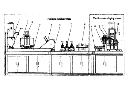
FIG. 1 is a structure diagram of the fuel area forming system and fuel-free
area
shaping system of the present disclosure;
FIG. 2 is a structure diagram of the fuel area forming system according to an
embodiment of the present disclosure;
FIG. 3 is a section view of the nuclear fuel particle evenly-distributing
device
according to an embodiment of the present disclosure;
FIG. 4 is a section view of the material canister workstation conveying device
according to an embodiment of the present disclosure;
FIG. 5 is a structure diagram of the secondary stirring device according to an
embodiment of the present disclosure;
FIG. 6 is a section view of the core sphere pressing device according to an
embodiment of the present disclosure;
FIG. 7 is a structure diagram of the fuel-free area shaping system according
to an
embodiment of the present disclosure;
FIG. 8 is a 3-D structure diagram of the fuel-free area shaping system
according to an
embodiment of the present disclosure.
DETAILED DESCRIPTION
5
CA 02999588 2018-03-22
The embodiments of the present disclosure will be described in detail with
reference
to the accompanying drawings hereinafter.
As shown in FIG. 1, a spherical fuel element forming apparatus, comprising: a
fuel
area forming system, a fuel-free area shaping system and a green sphere
pressing
system connected sequentially. The fuel area forming system is used for evenly
mixing a core sphere matrix powder with nuclear fuel particles and then
pressing the
mixed core sphere matrix powder and nuclear fuel particles into core spheres.
The
fuel-free area shaping system is used for preparing a spherical fuel element
from the
core spheres covered by a fuel-free matrix powder. The green sphere pressing
system
is used for pressing the spherical fuel elements into green spheres.
Specifically, as shown in FIG. 2, the fuel area forming system comprises a
core sphere
matrix powder quantitative conveying device 1, a nuclear fuel particle
evenly-distributing device 2, a nuclear fuel particle accurate quantification
device 3, a
primary stirring device 4, a discharge molding device 5, a secondary stirring
device 7
and a core sphere pressing device 8 arranged sequentially. The core sphere
matrix
powder quantitative conveying device 1, nuclear fuel particle accurate
quantification
device 3, primary stirring device 4 and discharge molding device 5 are
connected by a
material canister workstation conveying device 6. The core sphere matrix
powder
quantitative conveying device I quantitatively conveys the core sphere matrix
powder
to the material canister workstation conveying device 6. The nuclear fuel
particle
evenly-distributing device 2 and nuclear fuel particle accurate quantification
device 3
precisely and quantitatively conveys the nuclear fuel to the material canister
workstation conveying device 6. The material canister workstation conveying
device
6 conveys the core sphere matrix powder and nuclear fuel to the primary
stirring
device 4. The primary stirring device 4 stirs the core sphere matrix powder
and
nuclear fuel evenly. The material canister workstation conveying device 6
conveys the
core sphere matrix powder and nuclear fuel that passed through the primary
stirring
device 4 to the discharge molding device 5. The discharge molding device 5
fills a
core sphere die 7-0 with the core sphere matrix powder and nuclear fuel that
are
stirred evenly. The secondary stirring device 7 stirs the core sphere matrix
powder and
nuclear fuel in the core sphere die. The core sphere pressing device 8 presses
the core
sphere matrix powder and nuclear fuel in the core sphere die into core
spheres.
Wherein preferably, the core sphere matrix powder quantitative conveying
device 1
6
CA 02999588 2018-03-22
comprises a first hopper for storing the core sphere matrix powder and a
spiral feeder
at the bottom of the hopper, the conveying amount of the core sphere matrix
powder
is controlled by the feeding time of the spiral feeder. As shown in FIG. 3,
the nuclear
fuel particle evenly-distributing device 2 comprises a rotatable second hopper
2-1 for
receiving the nuclear fuel, a distribution tube 2-2 connected with the second
hopper
2-1 and a plurality of columnar containers 2-3 for receiving the nuclear fuel
distributed by the distribution tube. The plurality of columnar containers 2-3
are
integrally rotatable. Preferably, the plurality of columnar containers 2-3
have a
number of 50, and are arranged on a distribution plate. The plurality of
columnar
containers 2-3 are rotated by the rotation of the distribution plate. As shown
in FIG. 4,
the nuclear fuel particle accurate quantification device 3 comprises a balance
3-1 with
a bottom-suspension function, a weighing hopper 3-2 suspended at the bottom of
the
balance and a vibrating feeder 3-3 for adding nuclear fuel into the weighing
hopper
and capable of storing nuclear fuel. The bottoms of the columnar containers 2-
3 are
provided with tubes, through which the nuclear fuel in the columnar containers
2-3
which are rotated in place is conveyed to the weighing hopper 3-2 by the
rotatable
plurality of columnar containers 2-3.
Wherein preferably, as shown in FIG. 4, the material canister workstation
conveying
device 6 comprises an infrared position sensor, a chain driven by a motor and
a
plurality of material canisters 6-2 mounted on the chain; the infrared
position sensor is
for determining whether the opens of the plurality of material canisters 6-2
correspond
to the conveying port 6-1 of the core sphere matrix powder quantitative
conveying
device, the discharge port of the weighing hopper 3-2 of the nuclear fuel
particle
accurate quantification device 3, the primary stirring device 4 and the
discharge
molding device 5 respectively. By the motor driving the chain, the plurality
of
material canisters 6-2 on the chain are conveyed to the primary stirring
device 4
through the conveying port 6-1 of the core sphere matrix powder quantitative
conveying device 1 and the discharge port of the weighing hopper 3-2 of the
nuclear
fuel particle accurate quantification device 3, and the mixed material after
the primary
stirring is conveyed to the discharge molding device 5.
Wherein preferably, as shown in FIG. 5, the secondary stirring device 7
comprises a
base plate 7-1 for placing the core sphere die 7-0 which is filled with the
core sphere
matrix powder and nuclear fuel, a bracket 7-3 and a rotatable stirring head 7-
2
mounted on the bracket; the stirring head 7-2 extends into the inner cavity of
the core
7
CA 02999588 2018-03-22
sphere die; under working conditions, the stirring head 7-2 is driven by a
motor to stir
the core sphere matrix powder and nuclear fuel in the core sphere die; the
base plate
7-1 is driven by a motor and rotatable, the rotation direction of the base
plate 7-1 is
opposite to that of the stirring head 7-2.
Wherein preferably, as shown in FIG. 6, the core sphere pressing device 8
comprises
an outer sleeve 8-1 which can move up and down, an upper punch 8-2 fixed in
the
outer sleeve 8-1 and an lower punch 8-3 which can move up and down; the outer
diameter of the core sphere die is the same as the inner diameter of the outer
sleeve
8-1, the outer diameter of the upper punch 8-2 and the outer diameter of the
lower
punch 8-3 respectively. The outer sleeve 8-1 may move up and down by a
cylinder,
the length of stroke is not greater than 300mm, the lower punch 8-3 may move
up and
down by hydraulic pressure, the pressure on the punch may be 40-120KPa.
Specifically, as shown in FIG. 7, the fuel-free area shaping system comprises
a core
sphere positioning-conveying device 9, a core sphere positioning-transferring
device
12, a fuel-free area matrix powder quantitative conveying device and a fuel-
free area
shaping device; the core sphere positioning-conveying device 9 and core sphere
positioning-transferring device 12 are used for transferring the core spheres
to the
fuel-free area shaping device; the fuel-free area matrix powder quantitative
conveying
device is used for conveying the matrix powder to the fuel-free area shaping
device;
the fuel-free area shaping device is used for coating the core spheres with
the matrix
powder so as to prepare the spherical fuel element.
Wherein preferably, as shown in FIG. 8, the core sphere positioning-conveying
device
9 comprises a disc 9-1 which can be rotated positionally, a plurality of
bosses 9-2 for
placing the core spheres are distributed evenly on the disc 9-1; preferably,
the bosses
9-2 for placing the core spheres with a number of 12 are distributed evenly on
the disc
9-1, the disc 9-1 can be rotated positionally by cylinder drive. The core
sphere
positioning-transferring device 12 comprises a mechanical gripper 12-1 and a
mechanical arm 12-2 for moving the mechanical gripper 12-1 in a horizontal or
vertical direction; the mechanical gripper 12-1 can move to be right above the
bosses
9-2 of the core sphere positioning-conveying device 9 and right above the die
of the
fuel-free area shaping device in the horizontal direction. Preferably, the
fuel-free area
shaping device comprises a lower hemisphere fuel-free area shaping device 11
and an
upper hemisphere fuel-free area shaping device 14. The fuel-free area matrix
powder
8
CA 02999588 2018-03-22
quantitative conveying device comprises a lower hemisphere fuel-free area
matrix
powder quantitative conveying device 10 and an upper hemisphere fuel-free area
matrix powder quantitative conveying device 13. An end in the horizontal
direction
along the mechanical arm 12-2 of the mechanical gripper 12-1 is right above a
place
where the core sphere positioning-conveying device 9 places a core sphere, the
other
end is right above the die of the upper hemisphere fuel-free area shaping
device 14.
The device can perform actions such as grabbing, lifting, horizontally moving,
lowering, placing the core spheres etc.
Wherein preferably, the fuel-free area shaping device comprises a movable base
plate
11-1 for placing a die, a probe for detecting the level of matrix powder and
an
arc-shaped scraper 11-3 for shaping the spherical fuel element; the center of
the
arc-shaped scraper 11-3 is on the vertical axis of the die. Preferably, the
lower
hemisphere fuel-free area shaping device 11 comprises a rotatable base plate
11-1 for
placing the lower half die of a final-pressing die, a bracket 11-2 which is
driven by a
cylinder and can move up and down, and an arc-shaped scraper 11-3 fixed
vertically
below the bracket, the base plate 11-1 is driven by a motor to rotate. A pair
of probes
for detecting the level of matrix powder is provided below the movable bracket
11-2,
when the matrix powder reaches the probes, the lower hemisphere fuel-free area
matrix powder quantitative conveying device 10 stops operation, meanwhile the
cylinder pushes the movable bracket to move upward. Preferably, the upper
hemisphere fuel-free area matrix powder quantitative conveying device 13 may
comprise a base plate 13-1 for placing the upper half die of a final-pressing
die, a pair
of probes 13-2 for detecting the level of matrix powder, the base plate 13-1
is driven
by a motor to rotate, the probes are on a powder-charge port of the final-
pressing die,
when the matrix powder reaches the probes, the upper hemisphere fuel-free area
matrix powder quantitative conveying device 13 stops operation. Preferably,
the upper,
lower hemisphere fuel-free area shaping device may be 4 base plates uniformly
distributed on a tumplate, wherein the 4 base plates may be respectively used
for the
fuel-free area shaping of the lower half die, placing the core sphere and
covering with
the upper half die, the fuel-free area shaping of the upper half die, and
replacing the
dies.
The green spheres which have a diameter slightly larger than a target size are
pressed
under a pressure no smaller than 300Mpa by the final-pressing die after
shaping of the
fuel-free shaping system, and finally by the green sphere pressing system,
wherein the
9
CA 02999588 2018-03-22
green sphere pressing system may be a quasi-isostatic pressing vacuum
hydraulic
machine.
The processes of shaping the spherical fuel element and pressing the green
spheres
with the spherical fuel element forming apparatus above are as follows:
S 1 : a batch of graphite as the core sphere matrix powder and the fuel-free
area matrix
powder is charged into the first hopper of the core sphere matrix powder
quantitative
conveying device and the fuel-free area matrix powder quantitative conveying
device
respectively;
S2: when a material canister on the material canister workstation conveying
device is
right below the spiral feeder, a certain amount of graphite matrix powder is
added into
the material canister automatically;
S3: 98% of the weight of the nuclear fuel particles containing 250gU are
poured into
the second hopper of the nuclear fuel particle evenly-distributing device,
divided into
50 equal parts and stored in the columnar containers; the remaining 2% of the
nuclear
fuel particles are added into the vibrating feeder, the nuclear fuel particles
in the
columnar containers flow into the weighing hopper suspended at the bottom of
the
balance by the rotating of the columnar containers, the amount for fine
adjustment is
added by the vibrating feeder;
S4: when a material canister on the chain of the material canister workstation
conveying device runs to be tight below the weighing hopper, the nuclear fuel
particles in the weighing hopper are added in the material canister which has
already
contained quantitative graphite matrix powder;
S5: the chain of the material canister workstation conveying device conveys
the
material canister containing the nuclear fuel particles and graphite matrix
powder to
the workstation of the primary stirring device which stirs he nuclear fuel
particles and
graphite matrix powder evenly;
S6: the chain of the material canister workstation conveying device also
conveys the
stirred nuclear fuel particles and graphite matrix powder to the discharge
molding
device which fills the core sphere die with the stirred nuclear fuel particles
and
graphite matrix powder;
S7: the core sphere die filled with material is placed on the secondary
stirring device
CA 02999588 2018-03-22
to be stirred;
S8: the core sphere die filled with material is placed on the core sphere
pressing
device to be pressed into core sphere, and the pressed core spheres are placed
on the
bosses of the core sphere positioning-conveying device;
S9: the fuel-free area shaping device is started and the trunplate thereof
rotates to 90
degrees, and drives the base plates on the tamp late, such that the lower half
die in the
base plate moves to the next workstation, the quantitative graphite matrix
powder is
conveyed to the lower half die by the lower hemisphere fuel-free area matrix
powder
quantitative conveying device;
S10: the core sphere positioning-conveying device is started and the
mechanical arm
controls the mechanical gripper to put the pre-pressed core spheres into the
lower half
die containing the graphite matrix powder, the core sphere is in the middle of
a die
cavity;
S11: the lower half die is covered with the upper half die, the trunplate of
the fuel-free
area shaping device is started to rotate another 90 degrees, such that the die
moves to
the next workstation, the upper hemisphere fuel-free area matrix powder
quantitative
conveying device injects quantitative graphite matrix powder into the die
cavity of the
die.
S12: then the dies are withdrawn from the tumplate of the fuel-free area
shaping
device and put into the quasi-isostatic pressing vacuum hydraulic machine to
be
pressed into green spheres.
The spherical fuel element forming apparatus provided by the present
disclosure is
distributed according to a technical process flow line operation, is compact
in
structure and convenient to operate. All the devices are connected rationally.
The
apparatus operation has a good logical relationship and easily realizes
automation.
With the fuel-free area shaping system, the sphere greens after being finally
pressed
are high in sphericity. Only few finish allowance is needed, and the waste of
graphite
matrix powder is reduced and the fuel element cost lowered. In addition, with
the
nuclear fuel particle evenly-distributing device and nuclear fuel particle
accurate
quantification device, the obtained ratio of nuclear fuel and matrix powder is
precise,
therefore the finished product rate of the spherical fuel elements prepared by
the
spherical fuel element forming apparatus of the present disclosure is high.
11
CA 02999588 2018-03-22
Although the embodiments of the present invention have been described in
conjunction with the accompanying drawings, various modifications and
variations
can be made by those skilled in the art without departing from the spirit and
scope of
the present disclosure, and such modifications and variations are within the
scope
defined by the appended claims.
12