Note: Descriptions are shown in the official language in which they were submitted.
84226294
STRUCTURES AND METHODS FOR THERMAL MANAGEMENT IN PRINTED
CIRCUIT BOARD STATORS
CROSS-REFERENCE TO RELATED APPLICATIONS
[0001] The present disclosure is related and claims priority to U.S.
Provisional Pat. Appl. No.
62/236,407, entitled STRUCTURES TO REDUCE LOSSES IN PRINTED CIRCUIT BOARD
WINDINGS, and to U.S. Provisional Pat. Appl. No. 62/236,422, entitled
STRUCTURES FOR
THERMAL MANAGEMENT IN PRINTED CIRCUIT BOARD STATORS, both to Steven It.
Shaw, filed on October 2, 2015.
BACKGROUND
Field of disclosure
[0002] Embodiments described herein are generally related to the field of
thermal management
in printed circuit board devices. More specifically, embodiments as disclosed
herein are related
to the field of thermal management in stators made on printed circuit boards
for electric motors
and generators.
Related art
[00031 Current electric motors and other electric devices handling high
currents through
electrical leads in a printed circuit board (PCB) face multiple problems
resulting from the large
heat dissipation in the PCB. Some of the problems include warping of the
substrate, which leads
to mechanical failure and destructive mechanical interferences with the rotor
of the motor or
generator. Moreover, high temperature gradients in the PCB may lead to
structural damage of
the PCB such as delamination or localized failure of the electrical leads or
the dielectric material
in the substrate. The rare-earth magnets typically employed in airgap printed
circuit board
machines are also temperature sensitive. If the magnet temperature exceeds a
specified value,
the magnets can degrade and lose their magnetic field.
[0004] Printed circuit board electric machines built without the features
described in this
disclosure, i.e., the current state-of-the art, employ a variety of strategies
to manage heat.
1
Date Recue/Date Received 2021-07-06
CA 02999999 2019-03-26
WO 2017/059213 PCT/US2016/054704
Collectively, these strategies limit the commercial appeal and marketability
of the basic printed
circuit board stator design. These strategies include a) oversizing the
machine relative to the
desired mechanical operating portion so that the machine structure acts as a
heat sink, b) actively
cooling the machine, c) introduce efficiency compromising features such as
larger air gaps
between the rotor and the stator, d) limiting the machine to intermittent-duty
applications, and/or
e) equipping the machine with temperature-sensing controllers.
SUMMARY
[0005] In a first embodiment, a stator includes a planar composite structure
(PCS) having at least
one dielectric layer and a plurality of conductive layers, the PCS
characterized at least in part by
a center origin point and a periphery. The stator may also include a plurality
of first conductive
elements extending radially to a distance r1 from the center origin point
toward the periphery of
the PCS and disposed angularly on the PCS, each first conductive element
terminated in a
preferred termination structure, and a plurality of second conductive elements
extending radially
from a radius r2 from the center origin point toward the periphery of the PCS
and disposed
angularly on the PCS. Further, according to some embodiments, at least one of
the first
conductive elements is connected to at least one of the second conductive
elements at the
preferred termination structure according to a connection configuration.
100061 In a second embodiment, a stator includes a PCS comprising at least one
dielectric layer
and at least one conductive layer, the PCS characterized at least in part by a
center origin point
and a periphery. The stator may also include a plurality of first conductive
elements extending
radially from a starting radius lb from the center origin point toward the
periphery of the PCS
and disposed angularly on the PCS, each first conductive element originating
in a preferred
starting structure. Further, the stator may include a plurality of second
conductive elements
extending radially from a radius r...1 from the center origin point toward the
center origin point of
the PCS and disposed angularly on the PCS. In some embodiments, at least one
of the first
conductive elements is connected to at least one of the second conductive
elements at the
preferred starting structure according to a connection configuration.
2
84226294
[0006a] According to an aspect of the present invention, there is provided a
planar
composite structure (PCS) configured for use as a stator of an axial flux
motor or generator,
the PCS comprising: at least one dielectric layer; first elongated conductive
elements
arranged angularly on the at least one dielectric layer, each of the first
elongated conductive
elements extending radially between a first radial distance from an origin
point associated
with the at least one dielectric layer and a second radial distance from the
origin point,
wherein the second radial distance is greater than the first radial distance;
conductive inner
end turns disposed on the at least one dielectric layer, each of the
conductive inner end turns
being connected between portions of at least two of the first elongated
conductive elements
at the first radial distance; conductive outer end turns disposed on the at
least one dielectric
layer, each of the conductive outer end turns being connected between portions
of at least
two of the first elongated conductive elements at the second radial distance;
and at least one
second elongated conductive element disposed on the at least one dielectric
layer, the at least
one second elongated conductive element extending radially between a third
radial distance
from the origin point and a fourth radial distance from the origin point,
wherein: the fourth
radial distance is greater than the third radial distance, either (a) the
fourth radial distance is
less than the first radial distance, or (b) the third radial distance is
greater than the second
radial distance, and the at least one second elongated conductive element is
thermally
connected to at least a first one of the first elongated conductive elements
without the at least
one second elongated conductive element also being electrically connected to
the first one of
the first elongated conductive elements.
10006b] According to another aspect of the present invention, there is
provided a planar
composite structure (PCS) configured for use as a stator of an axial flux
motor or generator,
the PCS comprising: at least one dielectric layer; first elongated conductive
elements
arranged angularly on the at least one dielectric layer, each of the first
elongated conductive
elements extending radially between a first radial distance from an origin
point associated
with the at least one dielectric layer and a second radial distance from the
origin point,
wherein the second radial distance is greater than the first radial distance,
a first one of the
first elongated conductive elements being disposed on a first surface of the
at least one
dielectric layer, and a second one of the first elongated conductive elements
being disposed
on a second surface of the at least one dielectric layer opposite the first
surface; conductive
inner end turns disposed on the at least one dielectric layer, each of the
conductive inner end
turns being connected between portions of at least two of the first elongated
conductive
2a
Date Recu/Date Received 2021-10-13
84226294
elements at the first radial distance; conductive outer end turns disposed on
the at least one
dielectric layer, each of the conductive outer end turns being connected
between portions of
at least two of the first elongated conductive elements at the second radial
distance; a second
conductive element disposed on the first surface, a first portion of the
second conductive
element being connected to a first portion of the first one of the first
elongated conductive
elements at the second radial distance; and a first via extending through the
at least one
dielectric layer, wherein the first via: is angularly offset from the first
portion of the first one
of the first elongated conductive elements, and electrically interconnects the
first one of the
first elongated conductive elements and the second one of the first elongated
conductive
elements through at least the second conductive element.
[0006c] According still another aspect of the present invention, there is
provided a planar
composite structure (PCS) configured for use as a stator of an axial flux
motor or generator,
the PCS comprising: at least one dielectric layer; first elongated conductive
elements
arranged angularly on the at least one dielectric layer, each of the first
elongated conductive
elements extending radially between a first radial distance from an origin
point associated
with the at least one dielectric layer and a second radial distance from the
origin point,
wherein the second radial distance is greater than the first radial distance;
conductive inner
end turns disposed on the at least one dielectric layer, each of the
conductive inner end turns
being connected between portions of at least two of the first elongated
conductive elements
at the first radial distance; conductive outer end turns disposed on the at
least one dielectric
layer, each of the conductive outer end turns being connected between portions
of at least
two of the first elongated conductive elements at the second radial distance;
a first outer
elongated conductive element disposed on the at least one dielectric layer and
extending
radially between a third radial distance from the origin point and a fourth
radial distance
from the origin point; and a second outer elongated conductive element
disposed on the at
least one dielectric layer and extending radially between the third radial
distance from the
origin point and the fourth radial distance from the origin point, wherein:
the fourth radial
distance is greater than the third radial distance, the third radial distance
is greater than the
second radial distance, and each of the first and second outer elongated
conductive elements
is thermally connected to a first one of the first elongated conductive
elements.
2b
Date Recu/Date Received 2021-10-13
CA 02999999 2019-03-26
WO 2017/059213 PCT/US2016/054704
BRIEF DESCRIPTION OF THE DRAWINGS
100071 FIG. IA illustrates a plan view of a stator including a PCS having at
least one dielectric
layer and a plurality of conductive layers, according to some embodiments.
[0008] FIG. 1B illustrates a cross-sectional view of a stator, according to
some embodiments.
10009] FIG. 2 illustrates a detail of the stator including a plurality of
conductive elements
disposed radially on the PCS, according to some embodiments.
100101 FIG. 3 illustrates a detail of an inner area proximal to a center
origin point of a stator,
including a plurality of conducting elements disposed radially and angularly
on the PCS,
according to some embodiments.
[0011] FIG. 4 illustrates a detail of an inner area proximal to a center
origin point of a stator,
including a plurality of conducting elements disposed radially, angularly, and
on different
conductive layers on the PCS, according to some embodiments.
[0012] FIG. 5 illustrates a detail of a conductive element including a
termination structure,
according to some embodiments.
[0013] FIGS. 6A-1 illustrate details of different connection configurations in
a stator, each
connection configuration including a first conductive element connected to a
second conductive
element at a termination structure, according to some embodiments.
[0014] FIGS. 7A-D illustrate thermal images of a stator including a planar
composite layer
(PCS) having at least one dielectric layer and a plurality of conductive
layers while dissipating
heat, according to some embodiments.
[0015] FIG. 8 illustrates a flow chart in a method for manufacturing a stator
including a planar
composite layer (PCS) having at least one dielectric layer and a plurality of
conductive layers,
according to some embodiments.
[0016] In the figures, elements and steps denoted by the same or similar
reference numerals are
associated with the same or similar elements and steps, unless indicated
otherwise.
3
CA 02999999 2019-03-26
WO 2017/059213 PCT/US2016/054704
DETAILED DESCRIPTION
[0017] Embodiments of the present disclosure differ from most in the broad
area of printed
circuit board thermal management in the sense that the heat originates in the
PCB stator
structure, and an objective of the embodiments of the disclosure is to convey
that heat for the
purpose of protecting the stator and surrounding components. Many advances in
recent years
focus on managing heat which originates in a sensitive component, and where
structures on the
printed circuit board are used as a heat sink, frequently with the objective
of eliminating a costly
discrete heat sink component. Embodiments of this disclosure are applicable to
single and
polyphase (e.g., three phase) motors and generators.
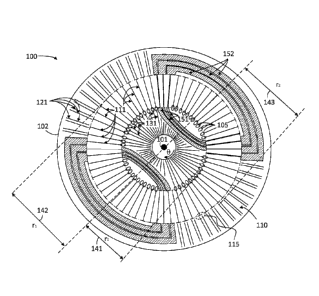
[0018] FIG. 1 A illustrates a plan view of a stator 100 including a planar
composite structure
(PCS) 110 having at least one dielectric layer and a plurality of conductive
elements 111, 121,
and 131, according to some embodiments. Conductive elements 111, 121 and 131
may be part
of a thermal mitigation structure in accordance with an embodiment of the
disclosure that can be
used at the outer annulus of a PCB structure. PCS 110 is characterized at
least in part by a center
origin point 101 and a periphery 102. Stator 100 includes a plurality of first
conductive elements
1 1 1 extending radially to a distance 142 (r1) from center origin point 101
toward periphery 102
of PCS 110 and disposed angularly on the PCS, each first conductive element
terminated in a
preferred termination structure 115. Further, in some embodiments stator 100
includes a
plurality of second conductive elements 121 extending radially from a radius
143 (r2) from
center origin point 101 toward periphery 102 and disposed angularly on the
PCS. Accordingly,
first conductive elements 111 are separated from one another along an angular
direction, 0,
perpendicular to the radial direction, r, from center origin point 101 to
periphery 102. Likewise,
second conductive elements 121 are separated from one another along direction,
0. In some
embodiments, at least one of the first conductive elements 111 is connected to
at least one of the
second conductive elements 121 at the preferred termination structure 115,
according to a
connection configuration.
[0019] Stator 100 may include multiple layers similar to the one illustrated
in the planar view of
FIG. 1A. The multiple layers may be arranged to provide a sequence of coils or
windings that
are connected, usually in series, to form the poles of a motor or generator.
The poles are then
4
CA 02999999 2019-03-26
WO 2017/059213 PCT/US2016/054704
typically segregated into groups, with at least one group for each phase of
current supplied to the
motor (or generated by the generator). Collectively, when properly controlled
by an external
electric circuit, the arrangement of conductors 111, 151, and 152 in PCS 110
creates a rotating
current density and associated magnetic field. This rotating current density
(and magnetic field)
can exert a torque on a surrounding magnetic structure or current density. The
part of the printed
circuit board with the radial structures (the "active area") is the part of
the stator designed to
participate in this interaction. Accordingly, the active area of stator 100
may include conductive
elements 111 coupled through conductive elements 151 and 152 to form the
rotating current.
Some embodiments include two sets of rare-earth magnets fixed to a shaft
passing through a
center origin point 101 of PCS 110, which forms a compact, high-efficiency
axial field
synchronous electric machine. In addition to the active area including a
rotating current density
that interacts with an inhomogeneous magnetic field, stator 100 may include
conductive
elements 121 in a peripheral area and conductive elements 131 in an interior
area. Accordingly,
conductive elements 121 and 131 dissipate heat generated by stator 100, while
in operation.
[0020] To achieve heat dissipation, some embodiments of stator 100 include
preferred
termination structures 115 and preferred starting structures 105 on either end
of the radially
disposed conductive elements 111. Thus, conductive elements 121 in the
peripheral area may be
coupled to conductive elements 111 through termination structures 115.
Conductive elements
131 in the interior area may be coupled to conductive elements 111 through
starting structures
105. Structures 105 and 115 include a connection configuration that may be a
thermal
connection, an electrical connection, or a combination of the two. For
example, a thermal
connection may be one where there is a physical gap between a conductive
element 111 and a
conductive element 121, so that there is no electrical connectivity between
the two elements.
Yet, the proximity of the two disconnected elements 111 and 121 may be
sufficient in a thermal
configuration to transmit heat efficiently from one conductive element to the
other (111 or 121).
100211 Heat is developed in stator 100 by multiple mechanisms. One mechanism
is resistive loss
in current-carrying conductors. This mechanism contributes power proportion to
the square of
the current and the effective resistance, i.e., Pjouie = /2R. The resistance R
may be approximately
proportional to the feature-width (e.g., in-plane width) as seen in stator
100, since copper
thickness and electrical resistivity is generally uniform. In vias, which
connect one layer to the
CA 02999999 2019-03-26
WO 2017/059213 PCT/US2016/054704
next, the copper electrical resistivity is somewhat higher than in the plane.
Also, as the
frequency of the current increases, it can be necessary to modify the
resistance R to include the
interaction of the current with its own magnetic field, e.g., the skin depth
effect. Practically, this
increases the resistance for higher-frequency components of the conducted
current, but does not
substantively change where the heat is generated on the stator.
[0022] A second mechanism of heat generation is related to the interaction of
copper (carrying a
current or not) with a time-varying magnetic field due to the rotor magnets.
For an area A
circumscribed by an associated contour C, there is an electric field along the
contour such that:
= di = ¨ ¨dt -11 = dA
A
[0023] where the direction of the differential area dil is related to di by
the right hand rule. In a
conductive material in the PCS, the electric field El leads to eddy-current
density and associated
losses anywhere there is a time-varying magnetic flux density R.. In general,
these eddy currents
also influence 11 leading to a magnetic diffusion equation, and a precise
calculation of loss must
take this into account. This is relevant to the radial active-area traces in
the stator assembly, due
to the rotating magnetic field that this portion of the stator is exposed to
whenever the shaft of
the rotor moves. These losses are in addition to any conductivity related
losses when the motor
is driven by an external circuit, and in fact this loss mechanism exists even
if stator 100 is not
connected to an external circuit.
[0024] A design consideration in stator 100 involves a trade-off between
conduction and eddy
current losses in the stator active area. To reduce conduction losses, the
conductors must be
wider (or connected in parallel on subsequent layers). To reduce eddy current
losses, the
effective areas A capturing time-varying flux must be smaller, thus the
conductors must be
narrower.
[0025] A third heat source involves eddy currents due to magnetic field from
current carrying
conductors. This effect is important to consider in the inner and outer
annulus of the board,
where different layers perform different functions. Also, it is important to
consider this
mechanism in the design of thermal mitigation structures.
6
CA 02999999 2019-03-26
WO 2017/059213 PCT/US2016/054704
100261 The dimensions and proportions of the different elements in stator 100
may vary as
desired. In some embodiments, it may be desirable that radius 142 (r1) be
equal to radius 143
(r2), resulting in no gap between one or more conductive elements 111 and 121.
In other
embodiments radius 142 (r1) may be smaller than radius 143 (r2), resulting in
a gap between one
or more conductive elements 111 and 121. Likewise, the materials forming the
different
elements in stator 100 may vary as desired, within the scope of the present
disclosure.
Accordingly, at least one of conductive elements 111, 121, 131, 151, and 152
may include
copper, or carbon (e.g., a graphene layer, or a carbon nano-tube layer, or
other carbon
allotropes), or a copper-carbon composite, or other electrically conductive
material or composite.
Conductive elements 121, 131 may include thermally conductive material.
100271 Accordingly, in embodiments consistent with the present disclosure
conductive elements
111, 121, and 131 act as thermal conductors having reduced areas dA for eddy
current loss.
Additionally, conductive elements 121 may enhance the thickness consistency of
stator 100
through the use of laminated copper traces in the peripheral area. Conductive
elements 131 are
heat removal traces on the inner area of stator 100. In some embodiments,
conductive elements
131 may be electrically connected to conductive elements 121 through starting
structures 105.
Accordingly, starting structures 105 are similar to termination structures
115. However, starting
structures 105 are typically radially distributed instead of angularly
distributed due to the spatial
constraints near center origin point 101.
10028] FIG. IB illustrates a cross-sectional view of stator 100, according to
some embodiments.
Without limitation and for illustration purposes, a 'Z' axis is shown in the
direction of the
stacking of the different layers in stator 100, and a perpendicular axis 'r'
is shown along its
cross-section. As seen, stator 100 may include a dielectric substrate 162
sandwiched between
conductive layers 161a and 16 lb. Vias 125 provide electrical conductivity
between conductive
layers 161a and 161b. In addition, vias 125 may also provide thermal
conductivity between
layers 161a and 161b due to the conducting material that is typically used in
these elements (e.g.,
copper, aluminum, tin, tungsten, and derived compounds). Dielectric substrate
162 may include
any material used in PCBs, such as a composite material including woven
fiberglass with an
epoxy resin binder (e.g., FR-4 and the like).
7
CA 02999999 2019-03-26
WO 2017/059213 PCT/US2016/054704
[0029] Accordingly, in some embodiments stator 100 includes at least one of
conductive
elements 111, 121, or 131 (cf. FIG. 1A) located on different conductive layers
161a and 161b.
For example, conductive element 111a may be one of the plurality of conductive
elements 111 in
the active area of stator 100 and disposed on conductive layer 161a.
Correspondingly,
conductive element 111b may be one of the plurality of conductive elements 111
in the active
area of stator 100 and disposed on conductive layer 161b. More generally,
conductive elements
121a (cf. FIG. 6A) and 131a correspond to conductive elements 121 and 131,
disposed on
conductive layer 161a. Likewise, conductive elements 121b (cf. FIG. 6A) and
131b correspond
to conductive elements 121 and 131, disposed on conductive layer 161b.
[0030] Conductive elements 111, 121 and 131 arranged in multiple conductive
layers 161a and
161b may improve heat dissipation in stator 100. Typically, heat is
disproportionately conveyed
via the electrically conductive elements themselves. For example, the thermal
conductivity of
copper (at 401 W/(m K)) is almost five hundred (500) times greater than the
thermal
conductivity of the surrounding dielectric material FR-4 (at 0.81 W/(mK) in-
plane). Further,
when the heat flows along the Z-direction, copper is even more significant as
a heat conducting
mechanism, having almost 1,400 times the thermal conductivity of FR-4 in the
out-of-plane
direction. Note that the overall thermal conductivity of the stator structure
depends on the
relative areas of the electrically conductive elements and surrounding
dielectric.
[0031] FIG. 2 illustrates a detail of stator 100 including a plurality of
conductive elements 111,
121 and 131, disposed radially on PCS 110, according to some embodiments. And
conductive
elements 152 disposed angularly on PCS 110. In some embodiments, stator 100
further includes
a plurality of third conductive elements 211 extending radially from a radius
241(r3) from center
origin point 101 toward periphery 102 and disposed angularly on PCS 110,
wherein at least one
of the third conductive elements 211 and at least one of the second conductive
elements 121b are
coincident and located on different conductive layers. For example, and
without loss of
generality, conductive elements 211 may be included in conductive layer 161a,
and conductive
elements 12 lb may be included in conductive layer 161b,
[0032] In some embodiments, thermal coupling between conductive elements 111,
121 and 131
is enhanced significantly by also making an electrical connection between
these conductive
8
CA 02999999 2019-03-26
WO 2017/059213 PCT/US2016/054704
elements. Accordingly, some embodiments provide clearances between conductive
elements
131 and conductive elements 111 in the inner area of stator 100, e.g., to
provide space for
conductive elements 151. Likewise, some embodiments provide clearances between
conductive
elements 111 and conductive elements 121 in the peripheral area of stator 100,
e.g., to provide
space for conductive elements 152. More generally, embodiments of stator 100
consistent with
the present disclosure provide electrical clearances between two conducting
elements that are at
different electric potentials, while still providing good thermal coupling
through a small gap of
dielectric material separating the two. Moreover, by providing strong thermal
connections to
different conductive layers through vias, this approach is particularly
effective (e.g., vias 125 and
conductive layers 162a and 162b, cf. FIG. 1B). Even if a conductive element is
interrupted on a
first conductive layer, a via section across conductive layers provides heat
removal from the first
conductive layer to a second conductive layer.
[0033] The electrical and thermal coupling between conductive elements 111 and
conductive
elements 131 includes a starting point of one of conductive elements 111 at a
distance 141 (r0)
from center origin point 101 contacting starting structure 105. And a starting
point of one of
conductive elements 131 at a distance 242 (r_1) from center origin point 101.
The opposite end
of conductive element 111 ends on termination structure 115 at a distance 142
(r1) from center
origin point 101.
[0034] FIG. 3 illustrates a detail of an inner area proximal to a center
origin point 101 of stator
100, including a plurality of conducting elements 111 and 131 disposed
radially and conductive
elements 151 disposed angularly on PCS 110, according to some embodiments. Due
to the
spatial constraints near center origin point 101, in some embodiments only
certain conductive
elements 131 may be thermally and/or electrically coupled to corresponding
conductive elements
111 through a starting structure 105. This arrangement avoids making
undesirable electrical
contact between adjacent conductive elements 131 near center origin point 101.
[0035] FIG. 4 illustrates a detail of an inner area proximal to center origin
point 101 of stator
100, including a plurality of conducting elements 111 disposed radially,
according to some
embodiments. A conductive element 151 is disposed angularly. And conductive
elements 431a
and 431b are disposed on different conductive layers on the PCS. To address
the issue of
9
CA 02999999 2019-03-26
WO 2017/059213 PCT/US2016/054704
thermal and electrical conductivity in the highly constrained space of the
inner area of PCS 110,
conductive elements 431a alternate with conductive elements 431b on different
layers of multi-
layer PCS 110. Inner vias in starting structures 105 dissipate heat through
conductive elements
ill. By staggering heat removal traces 431a and 43 lb in separate conductive
layers, they can
extend inward while maintaining a desired clearance between adjacent
conductive elements on
the same conductive layer. Other staggering configurations consistent with
this feature may be
envisioned, for example connecting every third conductive element 131 through
a via block.
[0036] FIG. 5 illustrates a detail of a conductive element 111 including a
termination structure
115, according to some embodiments. Termination structure 115 has a T-shaped
or
"hammerhead" configuration. In some embodiments termination structure 115 may
include a
square pad instead of a hammerhead configuration. Termination structure 115
improves the
angular distribution (i.e., along the 0 direction) of heat from different
sources in the transition
between the active and the peripheral areas of stator 100, such as eddy
currents and conductive
losses from conducting elements 111 ending at termination structure 115. In
addition,
termination structure 115 reduces the area wherein losses can occur due to
incident time-varying
magnetic fields (cf. Eq. 1).
[0037] Some embodiments include one or more vias between layers near the outer
portions of
termination structure 115, which in conjunction with the spatial extent of the
hammerhead
feature tends to reduce the angular concentration of heat compared to a single-
point thermal
termination (e.g., starting structure 105, cf. FIG. 1A). The hammerhead
feature of termination
structure 115 reduces the exposure of solid-copper elements in the peripheral
area to time
varying magnetic field leakage from the permanent magnet assembly over the
active area. The
specific dimensions and ratios shown in FIG. 2 may be subject to optimization
depending on
factors including a desired motor or generator design. Furthermore, the
disproportionate ratio of
thermal conductivity between the two basic materials in stator 100 (e.g.,
copper for conductive
elements 111, 121, and 131, vs. FR-4 in dielectric substrate 162) suggests
that different designs
of termination structure 115 that are substantially consistent with stator 100
and termination
structure 115, may be equally effective for heat dissipation.
CA 02999999 2019-03-26
WO 2017/059213 PCT/US2016/054704
[0038] FIGS. 6A-I illustrate details of different connection configurations
615a, 615b, 615c, and
615d (collectively referred hereinafter as connection configurations 615),
according to some
embodiments. Connection configurations 615 include first conductive elements
111a,b
connected to second conductive elements 121a,b at termination structure 115.
Termination
structure 115 includes vias 125 forming a thermal and electrical coupling
between conductive
elements 111a,b and conductive elements 121a,b. Three-dimensional axis (Z, r,
0) is consistent
with those shown in FIGS. 1A-B, and FIG. 2-4. Axis labeling and specific
orientation of the
elements in the figures are chosen for illustrative purposes only and should
not be deemed
limiting the different embodiments depicted.
[0039] FIG. 6A shows a perspective view of connection configuration 615a,
according to some
embodiments. Connection configuration 615a includes conductive elements 111a,b
and 121a,b
in two different conductive layers (e.g., conductive layer 161a and 161b, cf.
FIG. 1B), forming
an electrical and thermal coupling at termination structure 115. More
specifically, connection
configuration 615a provides electrical and thermal coupling between conductive
elements 111a,b
and conductive elements 121a,b.
[0040] FIG. 6B is a cross-section view of connection configuration 615a, along
the length of
conductive elements 111a,b and 121a,b illustrated in FIG. 6A. FIG. 6B also
shows
schematically the heat flow in connection configuration 615a from conductive
elements 111a,b
to conductive elements 121a,b and ultimately to heat sink 620. In some
embodiments, it is
desirable that conductive elements 121a and 121b be at least partially
coincident but located in
opposite conductive layers of PCS 110. Accordingly, the heat flow from
conductive elements
111a,b to conductive elements 121a,b is enhanced along the radial path of
conductive elements
111a,b, and 121a,b.
[0041] FIG. 6C shows a plan view of connection configuration 615a including
conductive
elements 111a,b and 121a,b in the same conductive layer, forming an electrical
and thermal
coupling at termination structure 115. Termination structure 115 includes a
hammerhead feature
having four (4) vias 125 to provide enhanced heat dissipation and electrical
connection between
layers.
11
CA 02999999 2019-03-26
WO 2017/059213 PCT/US2016/054704
[0042] FIG. 6D shows a perspective view of connection configuration 615b
including
conductive elements 111a,b, 121a,b, and I52a in two different conductive
layers, forming an
electrical and thermal coupling at termination structure 115. More
specifically, connection
configuration 615b provides electrical and thermal coupling between conductive
elements I Ila,b
and conductive element 121b through vias 125 in termination structure 115.
Further, connection
configuration 615b provides thermal coupling between conductive element 111a
and conductive
element 121a on the same conductive layer, and with no electrical connection
between them.
Embodiments including connection configuration 615b may be desirable when
conductive
element 152a operates at a different electrical potential as either one of
conductive elements 111a
or 121a. Some embodiments including connection configuration 615b may be
desirable when
conductive element 121a operates at a different electrical potential as
conductive element 111 a.
[0043] FIG. 6E is a cross-section view of connection configuration 615b along
the length of
conductive elements Iii a,b and 121a,b illustrated in FIG. 6D. FIG. 6E also
shows schematically
the heat flow from conductive elements 111a,b to conductive elements 121a,b
into heat sink 620.
Because conductive elements 121a and 12 lb are at least partially coincident
along the plane of
PCS 110, heat flows from conductive element 121b to conductive element 121a
irrespective of
any difference in electrical potential between the two conductive elements.
[0044] FIG. 6F shows a perspective view of connection configuration 615c
including conductive
elements 111a,b, 121a,b and 152a in two different conductive layers, and
forming an electrical
and thermal coupling at termination structure 115. Connection configuration
615c is similar to
connection configuration 615b in that conductive elements 111a and 121a are
not electrically
connected, while conductive elements 111a,b is electrically and thermally
connected to
conductive element 12 lb through vias 125 in termination feature 115. However,
in connection
configuration 615c termination structure 115 has a hammerhead configuration
(cf. FIG. 5).
Accordingly, the heat flow from conductive elements 111 a,b to conductive
elements 121a,b in
connection configuration 615c is enhanced along the radial path of conductive
elements 111a,b,
and 121a,b, regardless of the electrical configuration.
100451 FIG. 6G is a cross-section view of connection configuration 615c along
the length of
conductive elements 111a,b (collectively, 111) and 121a,b (collectively 121)
illustrated in FIG.
12
CA 02999999 2019-03-26
WO 2017/059213 PCT/US2016/054704
6F. FIG. 6G also shows schematically the heat flow from conductive elements
111a,b to
conductive elements 121a,b into heat sink 620.
[0046] FIG. 6H shows a perspective view of connection configuration 615d
including
conductive elements 111, 121 and 152b in two different conductive layers,
forming an electrical
and thermal coupling at termination structure 115. Connection configuration
615d is similar to
connection configurations 615b and 615c in that conductive elements in
different conductive
layers are electrically and thermally connected (i.e., conductive element 111b
and conductive
element 121a, through vias 125). However, in connection configuration 615d
conductive
element 152b is disposed on another conductive layer of PCS 110. Accordingly,
it may be
desirable to electrically isolate conductive element 111b from conductive
elements 121b.
[0047] FIG. 61 is a cross-section view of connection configuration 615d along
the length of
conductive elements 111 and 121 illustrated in FIG. 6H. FIG. 61 also shows
schematically the
heat flow from conductive elements 111a,b to conductive elements 121a,b into
heat sink 620. As
shown, the heat flow from conductive elements ill a,b to conductive elements
121a,b in
connection configuration 615d is enhanced along the radial path of conductive
elements 111a,b,
and 121a,b, regardless of the electrical configuration.
[0048] FIGS. 7A-D illustrate thermal images of stators 700a and Mb
(collectively referred
hereinafter to as 'stators 700'), respectively, including PCS 110 having at
least one dielectric
substrate 162 and conductive layers 161a and 161b while dissipating heat,
according to some
embodiments. Stator 700a does not include conductive elements 111 and 121,
while stator 700b
does (cf. FIGS. 1A-B). Thermal images are obtained by introducing heat via
conduction loss in
selected locations on stators 700 to emulate the temperature distribution in
an operating motor or
generator. Heat sources and sinks in an operating motor or generator include
the surrounding
magnetic and mechanical components. This approach allows imaging and
comparison of
thermal performance between different stator designs consistent with
embodiments disclosed
herein.
[0049] Introducing heat via conduction includes configuring a power supply to
deliver a fixed
amount of power (approximately 20W) to stators 700 for 10 minutes. Stators 700
were then
imaged with a FUR digital IR camera. Boundary conditions were established by
placing stators
13
CA 02999999 2019-03-26
WO 2017/059213 PCT/US2016/054704
700 in an enclosure 750, leaving an exposed half of the stator available for
thermal imaging.
Additionally, only three of the four corners of PCS 110 were clamped firmly to
enclosure 750.
This clamping configuration allows a comparison of the efficacy of the thermal
designs in
removing heat from stators 700 to enclosure 750 with all other conditions held
constant. Stators
700 were excited across two of the three wye-connected phases.
[0050] FIG. 7A shows that stator 700a is hotter at the left-hand corner where
there is no good
thermal contact, the temperature is fairly uniform across stator 700a even
where it is well
terminated. This suggests that independent of the quality of the heat sinking
case, it is difficult
to convey heat out of stator 700a.
[0051] FIGS. 7B-D show the result of the same test and measurement procedure
for stator 700b,
including conductive elements 111 and 121 as disclosed herein (cf. FIGS. 1A-B,
2-5, and 6A-I).
Temperature readings in FIGS. 7A-7D are illustrative only and by no means
limiting of
embodiments disclosed herein. However, it is revealing that the parts of
stator 700b which are
clamped to enclosure 750 (darker portions in FIGS. 7B-D) are relatively cooler
than the parts
with poor thermal termination (brighter portions in FIGS. 7B-D). This suggests
that features
consistent with embodiments of the present invention are effective in removing
heat from stator
700b to enclosure 750.
100521 In FIG. 7C stator 700b shows a distinct pattern between the areas with
good thermal
termination and the corner with poor thermal termination. However, in this
case, the thermal
signature of the phases 710c immediately adjacent to the clamp is almost
entirely absent.
[0053] FIG. 7D shows the effect in FIG. 7C in further detail. Note the
difference between the
left-portion of the board (well clamped) and the right side (worse contact)
and the absence of a
sharp gradient in the radial direction (r, towards the sink), relative to the
angular direction (0, as
the boundary condition changes). Overall, a comparison the heat-removal
efficacy of stator 700a
with stator 700b shows that incorporating the features described in one or
more of the
embodiments of this invention (e.g., conductive elements 111, 121, and 131)
can remove heat
from the active region (which includes conductive elements 111) with
significantly greater
efficacy.
14
CA 02999999 2019-03-26
WO 2017/059213 PCT/US2016/054704
100541 FIG. 8 illustrates a flow chart in a method 800 for manufacturing a
stator including a
planar composite layer (PCS) having at least one dielectric layer and a
plurality of conductive
layers, according to some embodiments (e.g., stator 100, PCS 110, dielectric
substrate 162,
conductive layers 161a, b, cf. FIGS. 1A-B through FIG. 6).
[0055] Methods consistent with the present disclosure may include at least
some, but not all of
the steps illustrated in method 800, performed in a different sequence.
Furthermore, methods
consistent with the present disclosure may include at least two or more steps
as in method 800
performed overlapping in time, or almost simultaneously.
[0056] Step 802 includes forming a first conductive layer on the PCS by
radially disposing a first
conductive element on a dielectric substrate up to a first distance from a
center origin point of the
PCS (e.g., conductive layer 161a, dielectric substrate 162, and conductive
elements 111, 111a,b ,
cf. FIGS. 1A-B, and FIGS. 4 and 6A-I). Step 804 includes forming a second
conductive layer
opposite the first conductive layer on the PCS by radially disposing a second
conductive element
extending radially from a second distance from the center origin point of the
PCS (e.g.,
conductive layer 161b, and conductive elements 121, 121a,b , 131, 131a,b, 211,
cf. FIGS. 1A-B,
FIG. 2 and FIGS.4 and 6A-I). Step 806 includes coupling the first conductive
element with the
second conductive element through a termination structure (e.g., termination
structure 115, cf.
FIG. 1A). Step 808 includes forming a third conductive element on the PCS
extending radially
from a third distance from the center origin point of the PCS in one of the
first or second
conductive layers (e.g., conductive elements 121, 121a,b , 131, 131a,b, 211,
cf. FIGS. 1A-B,
FIG. 2 and FIGS.4 and 6A-I). Step 810 includes coupling the first conductive
element with the
third conductive element through a second termination structure (e.g.,
termination structures 105
or 115, cf. FIG. 1A).
[0057] In some embodiments, coupling the first conductive element with the
second or third
conductive elements may include any one of a thermal coupling, an electrical
coupling, or both.
Furthermore, the coupling may include a connection configuration having
starting and/or
termination structures including vias that go through the dielectric substrate
from one conductive
layer to another conductive layer (e.g., vias 125 and connection
configurations 615, cf. FIGS.
6A-I). In some embodiments, the first conductive element is in an active area
of the PCS and at
CA 02999999 2019-03-26
WO 2017/059213 PCT/US2016/054704
least one of the second or third conductive elements is in an inner area of
the PCS. Accordingly,
the termination structure may be radially oriented on the PCS due to spatial
constraints (e.g.,
termination structure 105). In some embodiments, when the second or third
conductive element
is in a peripheral area of the PCS, the termination structure may be angularly
oriented on the PCS
(e.g., termination structure 115).
100581 One skilled in the art will realize the invention may be embodied in
other specific forms
without departing from the spirit or essential characteristics thereof. The
foregoing embodiments
are therefore to be considered in all respects illustrative rather than
limiting of the invention
described herein. Scope of the invention is thus indicated by the appended
claims, rather than by
the foregoing description, and all changes that come within the meaning and
range of
equivalency of the claims are therefore intended to be embraced therein.
16