Note: Descriptions are shown in the official language in which they were submitted.
METHOD AND SYSTEM FOR CALCULATING A WIND ATTENUATION
CAUSED BY AN OBSTACLE IN A SIMULATION
TECHNICAL FIELD
The present invention relates to the field of vehicle simulators, and more
particularly to the
determination of the wind attenuation due to the proximity of obstacles.
BACKGROUND
The safe and efficient flight operation of modem helicopters has many
demanding aspects
for the crew and requires an extensive amount of training. This training on
the actual
aircraft can be costly, time consuming and involves a certain degree of risks.
Flight
simulators have been developed to alleviate some of these constraints and
their level of
fidelity has consistently improved over the years. In a typical training
scenario, pilots who
fly simulators can observe obstacles in the scene through a visual system. The
latter is built
based on databases that contain the topography of the terrain and physical
structures such as
buildings, walls, trees, bridges, etc. One challenge of creating a complete
simulation is the
interaction of the simulated aircraft with its simulated environment
represented through the
visual system and the weather selected by the instructor (winds, turbulence,
etc.). It is
possible to have the weather interact with the visual system and the typical
method used is
to generate a series of computational fluid dynamics (CFD) solutions that pre-
calculate the
flow and turbulence fields around the various structures contained in the
visual database.
For example, CFD solutions may be used for determining the blockage of wind
due to the
presence of an obstacle between the wind origin and the simulated aircraft.
However,
although they may generate precise solutions, such CFD methods are costly.
Therefore, there is a need for an improved method and system for determining
wind
attenuation caused by the proximity of obstacles in a simulation.
SUMMARY
According to a first broad aspect, there is provided a computer-implemented
method for
determining an attenuation of a wind caused by a simulated obstacle and
experienced by a
- 1 -
CA 3000120 2018-03-29
simulated vehicle in a simulation, comprising: receiving a wind direction and
an initial
speed for a simulated wind; generating a line of sight vector having a source
position, a
given direction and a given length, the given direction being one of opposite
to the wind
direction and identical to the wind direction; determining a distance between
the simulated
obstacle and the simulated vehicle using the line of sight vector, the
distance being at most
equal to the given length of the line of sight vector; determining a wind
attenuation gain
using the distance between the simulated obstacle and the simulated vehicle;
determining
an actual speed for the simulated wind using the initial speed of the
simulated wind and the
gain for the wind attenuation; and outputting the actual speed of the
simulated wind.
In one embodiment, the source position of the line of sight vector is located
on the
simulated vehicle.
In one embodiment, the source position is located along an axis orthogonal to
the wind
direction.
In one embodiment, the axis passes by a reference point located on the
simulated vehicle.
In one embodiment, the method further comprises varying the given direction
between a
first direction opposite to the wind direction and a second direction
identical to the wind
direction.
In the same or another embodiment, the method further comprises varying a
position of the
source position along the axis.
In one embodiment, said generating the line of sight vector comprises
generating a plurality
of line of sight vectors each having a respective source position located on
the simulated
vehicle, a respective direction and a respective length, the respective
direction for each one
of the plurality of line of sight vectors being one of opposite to the wind
direction and
identical to the wind direction.
In one embodiment, said determining the distance between the simulated
obstacle and the
simulated vehicle comprising determining a respective distance between each
respective
source position and the simulated obstacle.
- 2 -
CA 3000120 2018-03-29
In one embodiment, the respective length is identical for each one of the
plurality of line of
sight vectors.
In one embodiment, the respective source position is located along an axis
orthogonal to the
wind direction.
-- In one embodiment, the respective direction is substantially orthogonal to
the axis.
In one embodiment, the respective direction is parallel to an Earth horizontal
plane.
In one embodiment, the axis passes by a reference point located on the
simulated vehicle.
In one embodiment, the respective source position of each one of the plurality
of line of
sight vectors is located along the axis.
-- In one embodiment, the respective source position of at least two of the
plurality of line of
sight vectors is identical, the respective direction for the at least two of
the plurality of line
of sight vectors being different.
In one embodiment, the respective source position of at least two of the
plurality of line of
sight vectors is different.
-- In one embodiment, said determining the distance between the simulated
obstacle and the
simulated vehicle comprises: accessing a visual database containing a
topography of a
simulated terrain and simulated physical structures; identifying the obstacle
as being the
closest object from the source position along the given direction, the closest
object being
one of a part of the simulated terrain and one of the simulated physical
structures and a
-- distance between the closest object and the source positon being at most
equal to the given
length of the line of sight vector; and determining a distance between the
source position
and the closest object, thereby obtaining the distance between the simulated
obstacle and
the simulated vehicle.
According to another broad aspect, there is provided a system for determining
an
-- attenuation of a wind caused by a simulated obstacle and experienced by a
simulated
-3 -
CA 3000120 2018-03-29
vehicle in a simulation, comprising: a communication unit for at least one of
receiving and
transmitting data, a memory and a processing unit configured for executing the
steps of the
above-described method.
According to a further broad aspect, there is provided a system for
determining an
attenuation of a wind caused by a simulated obstacle and experienced by a
simulated
vehicle in a simulation, comprising: receiving an initial speed for a
simulated wind; a
vector module configured for receiving a direction of a simulated wind and
generating a
line of sight vector having a source position, a given direction and a given
length, the given
direction being one of opposite to a wind direction and identical to the wind
direction; a
gain module configured for receiving a distance between the simulated obstacle
and the
simulated vehicle using the line of sight vector and determining a wind
attenuation gain
using the distance between the simulated obstacle and the simulated vehicle,
the distance
being at most equal to the given length of the line of sight vector; and a
speed module
configured for determining an actual speed for the simulated wind using the
initial speed of
the simulated wind and the wind attenuation gain and outputting the actual
speed of the
simulated wind.
In one embodiment, the system further comprises a distance module configured
for
determining the distance between the simulated obstacle and the simulated
vehicle using
the line of sight vector.
In one embodiment, the source position of the line of sight vector is located
on the
simulated vehicle.
In one embodiment, the source position is located along an axis orthogonal to
the wind
direction.
In one embodiment, the axis passes by a reference point located on the
simulated vehicle.
In one embodiment, the vector module is further configured for varying the
given direction
between a first direction opposite to the wind direction and a second
direction identical to
the wind direction.
- 4 -
CA 3000120 2018-03-29
In the same or another embodiment, the vector module is further configured for
varying a
position of the source position along the axis.
In one embodiment, the vector module is configured for generating a plurality
of line of
sight vectors each having a respective source position located on the
simulated vehicle, a
respective direction and a respective length, the respective direction for
each one of the
plurality of line of sight vectors being one of opposite to the wind direction
and identical to
the wind direction.
In one embodiment, the distance module is configured for determining a
respective distance
between each respective source position and the simulated obstacle.
In one embodiment, the respective length is identical for each one of the
plurality of line of
sight vectors.
In one embodiment, the respective source position is located along an axis
orthogonal to the
wind direction.
In one embodiment, the respective direction is substantially orthogonal to the
axis.
In one embodiment, the respective direction is parallel to an Earth horizontal
plane.
In one embodiment, the axis passes by a reference point located on the
simulated vehicle.
In one embodiment, the respective source position of each one of the plurality
of line of
sight vectors is located along the axis.
In one embodiment, the respective source position of at least two of the
plurality of line of
sight vectors is identical, the respective direction for the at least two of
the plurality of line
of sight vectors being different.
In one embodiment, the respective source position of at least two of the
plurality of line of
sight vectors is different.
-5 -
CA 3000120 2018-03-29
In one embodiment, the distance module is configured for: accessing a visual
database
containing a topography of a simulated terrain and simulated physical
structures;
identifying the obstacle as being the closest object from the source position
along the given
direction, the closest object being one of a part of the simulated terrain and
one of the
simulated physical structures and a distance between the closest object and
the source
positon being at most equal to the given length of the line of sight vector;
and determining a
distance between the source position and the closest object, thereby obtaining
the distance
between the simulated obstacle and the simulated vehicle.
BRIEF DESCRIPTION OF THE DRAWINGS
Further features and advantages of the present invention will become apparent
from the
following detailed description, taken in combination with the appended
drawings, in which:
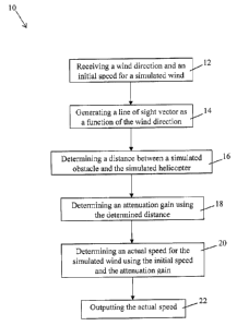
Figure 1 is a flow chart of a method for determining the attenuation of the
wind speed due
to an obstacle, in accordance with an embodiment;
Figure 2A illustrates a wind direction when a helicopter is partially located
between two
obstacles, in accordance with an embodiment;
Figure 2B is an exemplary graph of a wind gain attenuation as a function of a
position
along an axis;
Figure 3 illustrates the generation of a plurality of line of sight vectors
having their source
position located along the rotation axis of the main rotor of a simulated
helicopter, in
accordance with an embodiment;
Figure 4 is a block diagram illustrating a system for determining the
attenuation of the wind
speed due to an obstacle, in accordance with an embodiment; and
Figure 5 is a block diagram of a processing module adapted to execute at least
some of the
steps of the method of Figure 1, in accordance with an embodiment.
It will be noted that throughout the appended drawings, like features are
identified by like
reference numerals.
- 6 -
CA 3000120 2018-03-29
DETAILED DESCRIPTION
Figure 1 illustrates a computer implemented method for calculating the wind
attenuation
caused by an obstacle in a simulation. The method 10 is performed by a
computer machine
provided with communication means, a processing unit and a memory.
The simulation is configured for training a user to use a vehicle. An image of
an outdoor is
displayed on a display and the displayed image may correspond to what would be
seen by
the user if he would be within a real vehicle. For example, the vehicle may be
a rotor
aircraft such as a helicopter, a cyclogyro, a cyclocopter, an autogyro, a
gyrodyne, a rotor
bike, or the like.. While in the below description, reference is made to a
helicopter, it
should be understood that the method 10 may be used for any adequate simulated
vehicle or
entity such as a plane, a tank, a bicycle, a human, etc.
The simulator used for providing the simulation to the user comprises at least
a display on
which the simulated images are to be displayed, instruments for allowing the
user to control
the simulated vehicle and a simulation engine configured for generating the
simulation
using the commands received from the instruments and displaying the simulation
images on
the display. The simulator further comprises a database having stored thereon
at least
topography information about the simulated terrain and simulated structures
such as
buildings, walls, trees, bridges, and moving entities such as landable ships,
and/or the like.
For example, the database may contain information such as the position
information,
dimension information, information about the material from which a structure
is made,
and/or the like.
At step 12, information about the wind is received. The information comprises
the direction
of the wind and its initial speed or flow velocity. In one embodiment, the
information about
the wind is sent by the simulation engine and this information may be stored
in the database
along with other information such as the topography information. In one
embodiment, the
method 10 may further comprise a step of sending a request for information
about the wind
to the simulation engine. In this case, the simulation engine transmits the
information about
the wind upon receipt of the request.
- 7 -
CA 3000120 2018-03-29
At step 14, a line of sight vector is generated using the received wind
direction. A line of
sight vector is defined by a source position, a direction and a length. The
source position
may be located on the simulated helicopter. In another embodiment, the source
position
may be adjacent to the simulated helicopter. The direction of the line of
sight vector is
chosen to be either identical to the direction of the wind or opposite to the
direction of the
wind. The length of the line of sight vector defines the range for an obstacle
to have an
impact on the wind, i.e. the maximum distance for an obstacle to create wind
attenuation
for the simulated helicopter. As a result, if no obstacle is present over a
distance equal to
the length of the line of sight vector, then there is no attenuation for the
wind. However, if
an obstacle is present at a distance from the source position shorter or equal
to the length of
the line of sight vector, then the wind is attenuated for the simulated
helicopter.
At step 16, it is determined whether an obstacle is present along the line of
sight vector
generated at step 14. To do so, the distance between the source position and
the closest
obstacle from the source position along the direction of the line of sight is
calculated using
the topography information contained in the database. If no obstacle is
present, i.e. if the
distance between the closest obstacle from the source position along the
direction of the
line of sight is greater than the length of the line of sight, then no
attenuation for the wind is
calculated. On the other end, if the presence of an obstacle is detected, i.e.
if the distance
between the closest obstacle from the source position along the direction of
the line of sight
is less than or equal to the length of the line of sight, then an attenuation
for the wind is to
be calculated and steps 18-22 are performed.
It should be understood that an obstacle may correspond to a part of the
simulated terrain
stored in the database such as a hill and/or a simulated structure such as a
building or a
landable ship.
It should also be understood that if more than one obstacle is identified as
having a positon
within the range defined by the length of the line of sight vector, only the
obstacle being the
closest form the source position is considered and the distance determined at
step 16
corresponds to the distance between the source position and the closest
obstacle from the
source position.
- 8 -
CA 3000120 2018-03-29
At step 18, an attenuation gain for the wind is calculated using the
determined distance
between the source position of the line of sight vector and the identified
closest obstacle. In
one embodiment, the shortest the distance between the source position and the
closest
obstacle is, the greater the wind attenuation gain is.
At step 20, the actual or attenuated speed for the wind is calculated using
the initial speed
of the wind received at step 12 and the gain attenuation calculated at step
18. In one
embodiment, the attenuated speed of the wind is obtained by multiplying the
initial speed
by the calculated attenuation gain.
Finally, the attenuated speed of the wind is outputted. In one embodiment, the
attenuated
speed is stored in memory. In the same or another embodiment, the attenuated
speed is sent
to the simulation engine which uses the attenuated speed for controlling the
simulated
helicopter.
In one embodiment, the method 10 is executed in substantially real-time while
the user
interacts with the simulator to provide the user with a real-time effect of
the wind on the
simulated helicopter.
In one embodiment, the step 16 comprises sending to the simulation engine a
request for
receiving the distance of the closest obstacle from the source position of the
line of sight
vector. In this case, the request comprises at least the source position and
the direction of
the line of sight vector. The simulation engine receives the request and
determines the
distance of the closest obstacle from the source position along the direction
of the line of
sight vector. In one embodiment, the simulation engine transmits the
determined distance to
the computer machine that executes the method 10 and the computer machine
compares the
received distance to the length of the line of sight vector. If the distance
is greater than the
length of the line of sight vector, the computer machine calculates no
attenuation gain for
the wind. However, if the received distance is less than or equal to the
length of the line of
sight vector, the computer machine performs the steps 18-22 of the method 10
using the
received distance. In an embodiment in which the request further comprises the
length of
the line of sight vector, the simulation engine may be further configured for
comparing the
- 9 -
CA 3000120 2018-03-29
determined distance to the length of the line of sight vector and transmits
the determined
distance to the computer machine only when it is less than or equal to the
length of the line
of sight vector.
In one embodiment, the method 10 further comprises iteratively varying the
direction of the
line of sight vector between a first direction opposite to the direction of
the wind and a
second direction corresponding to that of the wind. In this case, the closest
obstacle is
identified for both the first and second directions and the distance to the
closest obstacle is
determined for both the first and second directions at step 16. An attenuation
gain is
calculated at step 18 for both the first and second directions using the
respective distance to
the closest obstacle. The attenuated speed of the wind is then calculated at
step 20 using the
attenuation gain for the first direction and the attenuation gain for the
second direction. For
example, the attenuated speed may be obtained by the multiplying the initial
speed of the
wind by the two attenuation gains obtained for both the first and second
directions.
In one embodiment, the method 10 further comprises varying the source position
of the line
of sight vector and performing the steps 16-22 for each possible position for
the line of
sight vector. It should be understood that the variation of the source
position may be
combined with the above-described variation of the direction of the line of
sight vector. For
example, the line of sight vector when at a first source position may have the
same
direction as that of the wind and have a direction opposite to that of the
wind when the
source position is at a second and different position. In another example, the
source position
may be set at a first position and the direction of the line of sight vector
may be first set to
correspond to that of the wind and then changed to be opposite to the
direction of the wind.
Then the source position of the line of sight vector is changed to a second
and different
position and the direction of the line of sight vector is also changed to
iteratively occupy the
two directions, i.e. the same direction as that of the wind and the direction
opposite to that
of the wind.
In one embodiment, the different source positions for the line of sight vector
may be chosen
to be on the simulated vehicle, i.e. on the simulated helicopter. The source
positions may be
chosen to each correspond to a main component of the simulated helicopter.
- 10 -
CA 3000120 2018-03-29
In one embodiment, the different source positions are located within the
azimuth plane of
the simulated helicopter. For example, the source positions may be aligned
along an axis
contained within the azimuth plane of the simulated helicopter. In another
embodiment, the
different source positions are located within the altitude plane of the
simulated helicopter.
For example, the source positions may be aligned along an axis contained
within the
altitude plane of the simulated helicopter.
In one embodiment, the generated line of sigh vector(s) is (are) parallel to
the Earth
horizontal plane.
It should be understood that the source positions may be chosen to cover
different points of
the simulated helicopter along the longitudinal axis of the simulated
helicopter from its
front end to its rear end for example, and/or on different points positioned
on the main rotor
of the simulated helicopter for example, and/or different points of the
simulated helicopter
along its vertical axis from its top to its bottom for example.
In one embodiment, the different source positions are aligned along an
interrogation axis 38
which is chosen to be orthogonal to the wind direction 39 as illustrated in
Figure 2. In the
illustrated embodiment, a simulated helicopter 40 is present between a first
obstacle 42 and
a second obstacle 44 so that the first obstacle 42 be positioned between the
wind source and
the simulated helicopter 40 and the simulated helicopter 40 be positioned
between the first
and second obstacles 42 and 44. The first obstacle 42 is said to be positioned
upstream from
the simulated helicopter 40 relative to the wind 39 while the second obstacle
44 is said to
be positioned downstream the wind 39 relative to the simulated helicopter 40.
The interrogation axis 38 is be chosen to be contained within the azimuth
plane of the
simulated helicopter 40 and passes by a reference point of the simulated
helicopter such as
a point belonging to the rotation axis of the main rotor of the simulated
helicopter 40.
Furthermore, and as mentioned above, the interrogation axis 38 is orthogonal
to the wind
direction 39. In the illustrated example, eight different source points 50-64
each
corresponding to a source position for the line of sight vector are chosen
along the
interrogation axis 38 to cover the whole projection of the simulated
helicopter 40 on the
- 11 -
CA 3000120 2018-03-29
interrogation axis 38. The first source point 50 is chosen along the
interrogation axis 38 so
as to correspond to the projection of most-front point of the simulated
helicopter 40 on the
interrogation axis 38. The last source point 64 is chosen along the
interrogation axis 38 so
as to correspond to the projection of most-rear point of the simulated
helicopter 40 on the
interrogation axis 38. The source points 52-62 are optionally evenly
distributed between the
points 50 and 64. In another embodiment, the source points 52-62 may be
distributed along
the interrogation axis so that to correspond to the positon of a main
component of the
simulated helicopter 40.
The source position of the line of sight vector is iteratively changed from
the first source
point 50 to the last interrogation point 64 and for each source point 50-64,
the direction of
line of sight vector is set to be first opposite to the wind direction 39 and
then identical to
the wind direction 39. For each source point 50-64 and each direction of line
of sight
vector, the steps 16 and 18 of the method 10 are performed so as to determine
the wind
attenuation gain for each source point 50-64 and each direction of line of
sight vector. For
each source point 50-64, a global attenuation gain is obtained by multiplying
together the
attenuation gains for the two line of sight vector directions. The resulting
global attenuation
gain as a function of the position of the source point position along the
interrogation axis 38
is illustrated in Figure 2B. For each source point 50-64, the attenuated wind
speed is
determined using the initial wind speed and the respective global attenuation
gain, i.e. by
multiplying the initial speed by the respective global attenuation gain.
Referring to Figure 2A, even if the source positions 50-54 and 58-64 are not
located on the
simulated helicopter 40, the attenuated wind determined for each one of these
points is
associated with at least one point on the helicopter of which the projection
corresponds to at
least one of the source positions 50-54 and 58-64. These associations can be
determined
using any adequate geometric interpolation method.
While in the above description, there is described that a single line of sight
vector is
generated at step 14, it should be understood that a plurality of line of
sight vectors may be
generated at step 14. In this case, each one of the plurality of line of sight
vectors has a
respective and different source position and/or a respective and different
direction. In this
- 12 -
CA 3000120 2018-03-29
case, for each line of sight vector, the respective distance from the closest
obstacle is
determined at step 16 and the respective gain attenuation is determined at
step 18. For each
source position, the global attenuation gain is calculated by combining
together the
attenuation gain for the line of sight vector having the source position and
the same
direction as that of the wind and the attenuation gain for the line of sight
having the same
source position and the direction opposite to that of the wind, i.e. by
multiplying together
the two attenuation gains obtained for the same source position. At step 20,
the attenuated
wind speed is determined for each source position using the initial wind speed
and the
respective global attenuation gain.
Referring to Figure 2A, a line of sight vector may be concurrently generated
for each
source point 50-64 and each of the two possible directions. In this case, 16
line of sight
vectors are concurrently generated. A first set of line of sight vectors is
generated for each
source position 50-64 and each line of sight vector contained in the first set
has a direction
opposite to that of the wind. A second set of line of sight vectors is
generated for each
source position 50-64 and each line of sight vector contained in the second
set has the same
direction as that of the wind. The distance from the closest obstacle and the
attenuation gain
is concurrently determined for each one of the 16 line of sight vectors and
the global
attenuation gain is concurrently determined for each one of the 8 source
positions 50-64.
In one embodiment, the different line of sigh vectors may each have a source
point located
on the simulated helicopter. In another embodiment, at least one of the line
of sight vectors
has a source position located on the simulated helicopter.
In one embodiment, the source position for the different line of sight vectors
are positioned
along an interrogation axis which is chosen to be orthogonal to the direction
of the wind, as
described above. In one embodiment, the interrogation axis intersects the
helicopter, as
described above.
While in Figure 2A the different source positions are located along an
interrogation axis 38
contained within the azimuth plane of the simulated helicopter 40, Figure 3
illustrates an
embodiment in which the line of sight vectors 80 and 82 each have a source
position
- 13 -
CA 3000120 2018-03-29
located along an interrogation axis 84 orthogonal to the wind direction and
contained in the
altitude plane of the simulated helicopter 86. In this illustrated embodiment,
five source
positions are defined along the interrogation axis 84 which is chosen to
correspond to the
rotation axis of the main rotor of the simulated helicopter 86. The five line
of sight vectors
80 each have the same first direction such as a direction opposite to that of
the wind and
each have a source position that corresponds to a respective one of the five
source points
located along the rotation axis 84 of the simulated helicopter 86. The five
line of sight
vectors 82 each have the same second direction which is opposite to the first
and each have
a source position that corresponds to a respective one of the five source
points located
along the rotation axis 84 of the simulated helicopter 86. In the illustrated
embodiment, the
three bottom-most line of sight vectors 80 allow the detection of an obstacle
88.
In one embodiment, a single line of sight is generated and its source position
and its
direction are iteratively changed so that the source position of the single
line of sight
iteratively occupies each one of the five source positions located on the
rotation axis 86 so
that the five line of sight vectors 80 and the five line of sight vectors 82
be iteratively and
successively generated. For example, the source position and/or the direction
of the single
line of sight vector may be changed at each simulation step.
In another embodiment, the five line of sight 80 and the five line of sight
vectors 82 are
concurrently generated.
In one embodiment, the distance to the obstacle used for the determination of
the
attenuation gain may correspond to the average distance obtained from the
particular
distances obtained using a plurality of line of sight having the same
direction but a different
source position. For example, and referring to Figure 3, the distances to the
obstacle 88
determined using three bottom-most line of sight vectors 80 can be averaged to
provide the
distance to be used in the calculation of the attenuation gain.
In one embodiment, the attenuation gain is normalized so that it may only have
a value
comprised between 0 and 1.
- 14 -
CA 3000120 2018-03-29
In the following, there is described one exemplary method for calculating the
attenuation
gain. For each source position such as each point of interest on the
helicopter, the
attenuation gain applied on the initial wind is defined by the following
equation:
Gi (di) = min (max ( d¨ Dm,n , 0.0), 1.0) = (1.0 ¨ Gmin) + Gmin
Dmax¨Dmin
where:
Gi (di) is the wind attenuation gain applied on a source position i as a
function of its
distance di from the obstacle;
di is the distance between a source position i and an obstacle;
Gmin is the minimum wind attenuation gain corresponding to a maximum blockage
effect;
Dmin is the minimum obstacle distance where a full wind blockage occurs and
the gain
G1 (d) is equal to Gmin; and
Dmax is the maximum obstacle distance where no blockage occurs and the gain Gi
(di) is
equal to 1Ø
This equation applies for obstacles located both upstream and downstream the
sources
positions and it should be understood that the value of the parameters defined
above may
vary from one source point to another.
The global gain Gi (di)final is computed by combining the two directions as
follows:
Gi (di)final = Gi (d
i) upstream = Gi OD downstream
It should be understood that other models may be used for calculating the
attenuation gain
using the distance to the closest obstacle.
It should be understood that the method 10 may be embodied as a computer
machine
comprising at least one processing unit or processor, a communication unit and
a memory
- 15 -
CA 3000120 2018-03-29
having stored thereon statements and/or instructions that, when executed by
the processing
unit, executes the steps of the above-described method.
Figure 4 illustrates one embodiment of a system 100 for calculating the wind
attenuation
for a simulated vehicle caused by a simulated obstacle. The system 100
comprises a line of
sight vector generator 102, an attenuation gain calculator 104 and a wind
speed calculator
106. The line of sight vector generator 102 is configured for generating at
least one line of
sight vector as described above. In one embodiment, the line of sight vector
generator 102
is configured for generating a single line of sight vector and varying the
source position
and/or the direction of the single line of sight vector. In another
embodiment, the line of
sight vector generator 102 is configured for generating a plurality of line of
sight vectors
each having a different direction and/or a different source position.
The line of sight vector generator 102 is further configured for transmitting
information
about the generated line of sight vector to a distance calculator 108. The
transmitted
information contains at least the source position and the direction of the
line of sight vector,
for each generated line of sight vector. The distance calculator 108 is
configured for
calculating the distance between the source position and the closest obstacle
along the
direction and transmitting the calculated distance to the attenuation gain
calculator 104, for
each line of sight vector.
In one embodiment, the line of sight vector generator 102 may further transmit
the length of
the line of sight vector to the distance calculator 108. In this case, the
distance calculator
108 may be configured for comparing the determined distance to the length of
the line of
sight vector and transmit the determined distance to the attenuation gain
calculator 104 only
when the determined distance is less than or equal to the length of the line
of sight vector. It
should be understood that, if the attenuation gain calculator 104 receives no
distance from
the distance calculator 108, then the attenuation gain calculator 104
calculates no
attenuation gain.
In another embodiment, the line of sight vector generator 102 may further be
configured for
transmitting the length of the line of sight vector to the attenuation gain
calculator 104. In
- 16 -
CA 3000120 2018-03-29
this case, the attenuation gain calculator 104 may be configured for comparing
together the
determined distance received from the distance calculator 108 and the received
length of
the line of sight vector and calculating the attenuation gain only when the
distance received
form the distance calculator 108 is less than or equal to the length of the
line of sight
vector.
For each line of sight vector, the attenuation gain calculator 104 is
configured for
calculating the attenuation gain using the respective distance received from
the distance
calculator 108, as described above. The attenuation gain calculator 104 is
further
configured for transmitting the calculated attenuation gain to the wind speed
calculator 106
which determines the wind speed as experienced by the simulated helicopter
using the
initial wind speed and the attenuation gain, as described above.
In one embodiment, the distance calculator 108 is separate from the system
100. In this
case, the distance calculator 108 may be the simulation engine configured for
generating
the simulation of the helicopter.
In another embodiment, the distance calculator 108 is part of the system 100.
In one embodiment, each one of the modules 102-108 is provided with a
respective
processing unit such as a microprocessor, a respective memory and respective
communication means. In another embodiment, at least two of the modules 102-
108 may
share a same processing unit, a same memory and/or same communication means.
For
example, the system 100 may comprise a single processing unit used by each
module 102-
106, a single memory and a single communication unit.
Figure 5 is a block diagram illustrating an exemplary processing module 120
for executing
the steps 12 to 22 of the method 10, in accordance with some embodiments. The
processing
module 120 typically includes one or more Computer Processing Units (CPUs)
and/or
Graphic Processing Units (GPUs) 122 for executing modules or programs and/or
instructions stored in memory 124 and thereby performing processing
operations, memory
124, and one or more communication buses 126 for interconnecting these
components. The
communication buses 126 optionally include circuitry (sometimes called a
chipset) that
- 17 -
CA 3000120 2018-03-29
interconnects and controls communications between system components. The
memory 124
includes high-speed random access memory, such as DRAM, SRAM, DDR RAM or other
random access solid state memory devices, and may include non-volatile memory,
such as
one or more magnetic disk storage devices, optical disk storage devices, flash
memory
devices, or other non-volatile solid state storage devices. The memory 124
optionally
includes one or more storage devices remotely located from the CPU(s) 122. The
memory
124, or alternately the non-volatile memory device(s) within the memory 124,
comprises a
non-transitory computer readable storage medium. In some embodiments, the
memory 124,
or the computer readable storage medium of the memory 84 stores the following
programs,
modules, and data structures, or a subset thereof:
a vector module 130 for generating at least one line of sight vector;
a distance module 132 for calculating the distance between the source
position of the line of sight vector and the closest obstacle along the
direction of the line of
sight vector;
a gain module 134 for calculating the attenuation gain using the calculated
distance; and
a speed module 136 for calculating the wind speed experienced by the
simulated vehicle using the attenuation gain.
It should be understood that the distance module 132 may be omitted.
Each of the above identified elements may be stored in one or more of the
previously
mentioned memory devices, and corresponds to a set of instructions for
performing a
function described above. The above identified modules or programs (i.e., sets
of
instructions) need not be implemented as separate software programs,
procedures or
modules, and thus various subsets of these modules may be combined or
otherwise re-
arranged in various embodiments. In some embodiments, the memory 84 may store
a
subset of the modules and data structures identified above. Furthermore, the
memory 84
may store additional modules and data structures not described above.
- 18 -
CA 3000120 2018-03-29
Although it shows a processing module 120, Figure 5 is intended more as
functional
description of the various features which may be present in a management
module than as a
structural schematic of the embodiments described herein. In practice, and as
recognized by
those of ordinary skill in the art, items shown separately could be combined
and some items
could be separated.
The embodiments of the invention described above are intended to be exemplary
only. The
scope of the invention is therefore intended to be limited solely by the scope
of the
appended claims.
- 19 -
CA 3000120 2018-03-29