Note: Descriptions are shown in the official language in which they were submitted.
CA 03000229 2018-03-27
WO 2017/070666
PCMJS2016/058456
A TRUCK MOUNTED VACUUM MATERIAL HANDLER, WITH QUICK CONNECTION
AND DISCONNECTION
BACKGROUND
The present invention relates to hydraulic disconnect systems designed to
attach a
vacuum plate handler or lifter to a truck-mounted boom.
Thick steel plates are commonly used on construction projects to cover hazards
that
range from 10-foot deep trenches across a road to a 6-inch difference in a
sidewalk. Plate
thicknesses in the neighborhood of one inch are not uncommon to support the
weight of a car
or truck as it crosses one of these openings.
These plates are typically delivered to the worksite by truck and their
footprint is
sized accordingly, typically 8- to 10-feet wide by 10- to 40-feet long. This
size also provides
sufficient weight and friction with the road surface to ensure it is not moved
from its installed
position by a braking or accelerating vehicle driving over the plate. Given
these dimensions
the plates typically range from 2,000 to 6,000 pounds.
Moving these plates has traditionally been accomplished by using a boom
mounted on
a flatbed truck. The plate is loaded and unloaded off the flatbed by a spring-
loaded
mechanism that is raised and lowered by a cable from the boom. The spring-
loaded
mechanism is extended through a rectangular hole in the center of the plate.
Once the
mechanism is inserted in this hole it expands to grab the sides of the hole.
The plate can then
be lifted. The spring-loaded mechanism and its use is well known in the field.
The prior art system for moving and lifting the plates has some significant
problems.
As the spring-loaded mechanism gets worn it can develop problems deploying to
grab the
hole in the plate. The hole in the plate can also become worn or blocked with
debris that
makes the connection between the spring loaded mechanism and the hole
questionable. When
CA 03000229 2018-03-27
WO 2017/070666
PCT/1JS2016/058456
2
the spring-loaded mechanism fails the plate will fall, presenting a risk for
extreme personal
injury and property damage.
The prior art system also suspends the spring-loaded mechanism and plate from
the
boom by a cable. This means the plate must be manually rotated about the cable
by an
operator next to the plate as it is being maneuvered into place. If the spring-
loaded
mechanism fails at this point it can land on the operator causing severe
injury.
Even for an experienced operator, there are limits to how much a 6,000 pound
plate
suspended from a cable can be maneuvered. Therefore, the prior art system has
limitations as
to its ability to place the plate in confined locations.
The trucks used to deliver the plates also deliver other items such as trench
cribbing
and miscellaneous excavation and safety equipment. Because different lifting
equipment or
attachments must be used, the trucks material handler or lifter attachments
must be changed
over to lift and place this equipment.
What is needed, therefore, is a system and method for safely picking up and
placing a
steel plate, precisely maneuvering a steel plate into confined locations, and
adaptable for
lifting and placing other items.
CA 03000229 2018-03-27
WO 2017/070666
PCT/US2016/058456
3
SUMMARY OF THE INVENTION
Preferred embodiments of a truck-mounted vacuum lifter include a coupler that
has a
boom connector, a removable carrier that has a carrier connector, and a base
located between
the boom connector and the removable carrier. A locking mechanism located in
the base is
arranged to move between an unlocked position and a locked position relative
to the carrier
connector. The base may include an opening shaped complementary to the carrier
connector
and arranged to receive the carrier connector.
In the unlocked position the carrier connector is removable from the base and
in the
locked position the carrier connector is secured in the opening and opposing
face surfaces of
the base and removable carrier are mated to one another. The base has a
landmark and the
removable carrier has a complementary shaped opening to the landmark so that
base and
removable carrier can connect to one another in only one orientation.
The removable carrier may include a rotator-receiving recess arranged opposite
the
carrier connector and shaped complementary to a rotator connected to a frame
of the truck-
mounted vacuum lifter. Alternatively, the removable carrier may include a
rigging hardware
eyelet arranged opposite the carrier connector.
A fluid power source, which may be located on or within the frame of the
vacuum
lifter, is in communication with the means arranged to move the locking
mechanism between
an unlocked position and a locked position relative to the carrier connector.
The base and
removable carrier have one or more fluid passageways that are aligned and in
communication
with one another when the locking mechanism is in the locked position. The
locking
mechanism can be a race with balls and a locking ring that surrounds the race
and urges the
balls into a groove of the base's carrier connector opening.
CA 03000229 2018-03-27
WO 2017/070666
PCT/US2016/058456
4
DESCRIPTION OF THE DRAWINGS
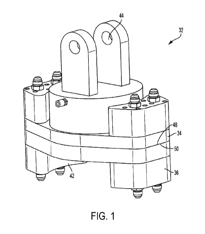
FIG. I is a perspective view of a preferred embodiment of a coupler to connect
a
boom to a vacuum material handler.
FIG. 2 is a perspective view of the coupler's base.
FIG. 3 is a perspective view of a first removable carrier used to secure the
vacuum
lifter to the coupler's base.
FIG. 4 is a perspective view of a second removable carrier used to provide an
eyelet
for use with other rigging hardware such as a hook, chain or cable.
FIG. 5 is a cross section of the coupler in the open position.
FIG. 6 is a cross section of the coupler in the locked position;
FIG. 7 is a perspective view of the coupler connected to the boom and a vacuum
lifter.
FIG. 8 is a perspective view of the frame of the vacuum lifter of FIG. 7.
CA 03000229 2018-03-27
WO 2017/070666
PCT/US2016/058456
Drawing Element Numbers
20 Vacuum material handler or lifter
22 Boom
24 Truck
5 26 Base of 22
28 End of 22
30 Rotator
32 Coupler
34 Base
36 First removable carrier
38 Second removable carrier
40 Eyelet
42 Recess
44 Connector to 28
46 Pin
48 Mating surface or face of 34
50 Mating surface or face of 36
52 Landmark
54 Pin
56 Opening to receive 54
58 Hydraulic connections
60 Connector (e.g. cylinder)
62 Mating surface or face of 38
64 Groove
66 Locking mechanism
68 Opening shaped complementary to 60
70 Race
72 Holes
74 Ball
76 Locking ring
78 Hydraulic or pneumatic cylinder
80 Biasing means
82 Onboard hydraulic motor
84 Vacuum pump
86 Alternator
88 Vacuum pads
90 Legs
92 Frame
94 Vertical plate
96 Horizontal flanges
98 Foundation
100 Eyelets
6
DESCRIPTION OF THE EMBODIMENTS
Referring first to FIGS. 1 & 7, a preferred embodiment of a coupler 32 for use
with a
truck-mounted vacuum material handler and quick disconnect secures a vacuum
handler or
lifter 20 to the end 28 of a telescopic boom 22 (mounted on a flatbed truck,
not shown) A removable
carrier 36 connects the vacuum lifter 20 to the coupler 32. The coupler 32 is
attached to the
end 28 of the boom 22 by a pivotal connection 44 that includes a pin 46.
(Other types of
joints could be used.)
Once connected, the boom 22 rotates about its base to position the vacuum
lifter 20
in various places relative to the truck 24, tilts the boom 22 up or down, or
extends and retracts
the boom 22. The vacuum lifter 20 can be rotated about the end 28 of the boom
22 via
operation of a rotator 30.
For lifting a thick steel plate, the vacuum lifter 20 has a pair of vacuum
pads 88, each
in communication with their own vacuum reservoir. A first solenoid-operated
valve opens
and closes fluid communication between the vacuum pad 88 and its respective
vacuum
.. reservoir. A second solenoid-operated valve provides the ability to open
the vacuum pad 88
to atmosphere and release the vacuum pressure between the pad 88 and the plate
the pad is
lifting.
The vacuum lifter 20 is provided with a set of retractable legs 90 which can
be
lowered to store the vacuum lifter 20 on a flat surface without the pads 88
coming in contact
.. with the surface. In the embodiment shown, the retractable legs 90 are
pivotally connected to
the lifter 20 and can be secured in a deployed position or a stowed position.
Other types of
connections can also be used,
Referring to FIG. 8, the frame 92 of the vacuum lifter 20 is constructed from
a vertical
plate 94 with a plurality of horizontal flanges 96 to provide rigidity. The
frame 92 has a
foundation 98 for mounting the rotator 30 and an open bay (not numbered) for
locating on
CA 3000229 2019-01-21
CA 03000229 2018-03-27
WO 2017/070666
PCT/US2016/058456
7
board equipment such as a hydraulic motor, vacuum pump, alternator, and
battery. A
plurality of eyelets 100 on the bottom of the frame 92 provide a mounting
point for the
vacuum pads 88.
Turning now to FIGS. 1 to 6, the coupler 32 has a base 34 that can connect to
a first
removable carrier 36 or a second removable carrier 38. The first removable
carrier 36 is used
to secure the vacuum lifter 20 to the coupler's base 34. This carrier 36
includes a
complementary shaped recess 42 to receive the rotator 30 and fastener holes
(not numbered;
see FIG. 3) to receive fasteners that connect the carrier 36 to the rotator
30. The second
removable carrier 38 is used to provide an eyelet 40 for use with other
rigging hardware such
as a hook, chain or cable. Both carriers 36, 38 are arranged to quickly attach
to and
disconnect from the base 34.
The mating surface 48 of the base 34 is complementary to the mating surface 50
of
the first carrier 36. A landmark 52 ensures the base 34 and first removable
carrier 36 can only
connect in one orientation. In a preferred embodiment, the landmark 52 is a
pin 54 that
extends from the mating face 48. When the base 34 is connected to the first
carrier 36, the pin
54 extends into a complementary opening 56 in the mating surface 50. The
mating surfaces
48 and 50 also include one or more hydraulic connections 58. These connections
58 provide
hydraulic fluid supply and return that power the rotator 30 and an onboard
hydraulic motor
82. The motor 82 can power other equipment on the vacuum lifter 20 such as a
vacuum pump
84 or alternator 86 (see FIG. 7).
A locking mechanism 66 secures the removable carriers 36 and 38 to the base
34. The
locking mechanism 66 has a cylinder 60 that extends from the mating surface
50, 62 of its
respective carrier 36, 38. A groove 64 extends around the side of the cylinder
60. The locking
mechanism 66 also has an opening 68 that is sized and located to receive the
cylinder 60
when the first or second carrier 36, 38 is attached to the base 34.
CA 03000229 2018-03-27
WO 2017/070666
PCT/US2016/058456
8
The opening 68 has a race 70 with a plurality of holes 72 each carrying a ball
74. The
race 70 extends around the interior periphery of the opening 68, such that the
balls 74 extend
into the opening 68 when the locking mechanism 66 is in the closed or locked
position. In the
locked position a locking ring 76 extends around the race 70 forcing the balls
74 to extend
beyond the holes 72 in the race 70 and into the opening 68.
In a preferred embodiment, the locking ring 76 is a part of or connected to a
hydraulic
or pneumatic cylinder 78. Operation of the cylinder 78 moves the locking ring
76 between the
open and locked positions. In the embodiment shown, a biasing means 80,
preferably one or
more springs, holds the locking ring 76 in the locked position. The hydraulic
or pneumatic
cylinder 78 can then be operated to overcome the force of the biasing means 80
and move the
locking ring 76 to the open position.
When the locking mechanism 66 is in the locked position and the first or
second
carrier 36, 38 is in the opening 68, the carrier 36, 38 is secured to the base
34 by the balls 74
extending into the groove 64. When the locking mechanism 66 is in the open
position, the
locking ring 76 moves out of alignment with the race 70. This allows the balls
74 to roll
radially outward away from the opening 68 and out of the groove 64 so the
first or second
carrier 36, 38 can removed from the opening 68.
The foregoing description details certain preferred embodiments of the present
invention and describes the best mode contemplated. Changes may be made in the
details of
construction and the configuration of components without departing from the
spirit and scope
of the disclosure. Therefore, the description is exemplary, rather than
limiting, and the true
scope of the invention is defined by the following claims and the full range
of equivalency to
which each element of the claims is entitled.