Note: Descriptions are shown in the official language in which they were submitted.
CA 03000639 2018-03-29
WO 2017/103562
PCT/GB2016/053693
1
CONDUCTIVE FABRIC, METHOD OF MANUFACTURING A
CONDUCTIVE FABRIC AND APPARATUS THEREFOR
Field of the Invention
The present invention relates to a conductive fabric, to a method of
manufacture of such a fabric and to weaving apparatus arranged to weave such a
fabric. In particular, the teachings herein can provide a fabric incorporating
a
plurality of conductive yarns into a woven fabric sheet, with the conductive
yarns
being present in both the warp and weft directions of the fabric. The
teachings
herein can also be used to weave electronic circuits and circuit components
into
the fabric.
Background Art
There have been many attempts over recent years to manufacture fabrics
having conductive elements therein, useful for a variety of applications
including
communication, powering peripheral devices, data transfer or collection,
sensing
and the like. Early devices sought to form multi layered structures, intended
to
create physical separation between the plurality of conductors in the
structure.
These devices, however, were bulky, unreliable and prone to delamination.
In the applicant's earlier EP-1,269,406 and EP-1,723,276 fabric weave
structures are disclosed which have proven to provide a reliable conductive
fabric
structure with inter-crossing conductive yarns which may be kept separate from
one another, arranged to touch one another under pressure or permanently
connected together. There are also described electronic components formed by
the conductive yarns. The structures disclosed in these applications have been
found to work very reliably and to have good longevity. There is now a need
for a
fabric having larger conductors, for example for delivering more power through
the
fabric, and for use in harsh and demanding conditions.
Other examples of conductive fabrics can be found in US-3,711,627 and
US-3,414,666. The disclosures in these documents disclose impregnating the
CA 03000639 2018-03-29
WO 2017/103562
PCT/GB2016/053693
2
fabric with plastic substances such as polyester resins or an elastic
insulating
compound for reliability and preventing short circuits. However, coating or
impregnating a textile is undesirable for a number of reasons. It adds expense
and additional complication to the manufacturing process, as well as rendering
the
textile heavier, thicker and stiffer. These latter effects compromise some of
the
very qualities that may be sought and desirable from the outset in a
conductive
textile.
It is important to minimize the risk of undesired short circuiting of the
conductors in the fabric. This risk increases when the textile is worn upon
the
body, where it can be subjected to bending, creasing and the incidence of
pressure. The risk is also greater when the diameter of the conductive yarns
is
larger, which limits the diameter of conductive yarns which may reliably be
employed, in turn limiting the linear conductivities of the yarns. This
results in
increased resistances within the textile circuits created, which decreases
electrical
.. efficiency and ultimately limits the operating current and power of the
circuits.
Summary of the Invention
The present invention seeks to provide an improved conductive fabric, a
method of manufacture of such a fabric and weaving apparatus arranged to weave
such a fabric. In particular, the preferred embodiments described herein can
provide a fabric incorporating a plurality of conductive yarns into a woven
fabric
sheet, with the conductive yarns being present in both the warp and weft
directions
of the fabric. The teachings herein can also be used to weave electronic
circuits
and circuit components into the fabric.
According to an aspect of the present invention, there is provided a woven
fabric formed of a first set of yarns extending in a first direction and a
second set of
yarns extending in a second direction, the first and second sets of yarns
being
woven together, the first set of yarns including at least one first electrical
conductor
and the second set of yarns including at least one second electrical
conductor, the
first and second electrical conductors crossing over one another at a crossing
point, wherein a non-conductive element in the form of at least one non-
conductive
CA 03000639 2018-03-29
WO 2017/103562
PCT/GB2016/053693
3
yarn of the first set of yarns is interposed directly between the first and
second
electrical conductors at the crossing point to provide a physical barrier
between
the first and second electrical conductors; wherein the non-conductive element
is
formed of at least two non-conductive yarns of the first set of yarns, and
wherein
the at least two non-conductive yarns extend on opposing sides of the first
conductor and are laterally arranged over the first conductor at the crossing
point
so as to be interposed between the first and second conductors at the crossing
point.
The fabric incorporates a physical barrier formed from at least one
non-conductive yarn of the fabric, which in practice prevents the crossing
conductors from coming into contact with one another and creating a short
circuit.
The structure is much more stable and robust than prior art systems, without
compromising on the characteristics of the fabric. It is not necessary to have
insulating coatings or to rely on a simple spacing between the crossing
conductors.
In practice, the at least two non-conductive yarns extending on opposing
sides of the first conductor are laterally biased so as to be deflected over
the first
conductor at the crossing point.
The arrangement creates a very reliable and robust separation between the
crossing conductors and can create an optimum structure resilient to
significant
bending and folding of the fabric. In some embodiments the at least two
non-conductive yarns may be obtained from a common side relative to the first
conductor.
In the preferred embodiment, the second set of yarns incudes at least one
.. non-conductive floating yarn extending over said non-conductive element at
the
crossing point. This non-conductive floating yarn or yarns is advantageously
disposed below the second conductor at the crossing point, such that the first
and
second conductors are disposed on opposing sides of said non-conductive
element and said non-conductive floating yarn or yarns at the crossing point.
This
non-conductive floating yarn or yarns of the second set can act to compact the
yarn or yarns of the non-conductive element together and over the first
conductor,
creating a stable arrangement of yarns.
CA 03000639 2018-03-29
WO 2017/103562
PCT/GB2016/053693
4
In a practical embodiment, there may be provided first and second spacer
non-conductive yarns in said second set of yarns, said first and second spacer
yarns being disposed between said non-conductive yarn of the second set and
the
second conductor. The spacer yarns in effect separate the second conductor
from
the compacting yarn and create a double compaction function, of the compacting
yarn and then of the second conductor.
Advantageously, the first set of yarns includes first and second tie yarns
extending over the second conductor to hold the second conductor in position.
In
practice, the tie yarns preferably extend across the second conductor in
between
adjacent parallel first conductors within the weave.
Preferably, the first and second conductors are conductive yarns. These
may be a composite structure for example having a nylon, polyester or aramid
core coated in or braided over by a conductive material such as silver, gold,
copper, brass, stainless steel or carbon.
In the preferred embodiment, the non-conductive element has a greater
number of strands than a number of strands of the first conductor. In
practice, a
greater number of strands can create a significant barrier between the
crossing
conductors and can enable the non-conductive element to have a greater lateral
width in the weave, which improves robustness and reliability of the fabric.
For
these and similar purposes, the non-conductive element may have a greater
width
than a width of the first conductor and/or may be laterally expandable
relative to
the first conductor.
In a practical implementation, the woven fabric includes a plurality of first
and second conductors and a plurality of crossing points therebetween, at
least
one of the crossing points having non-conductive elements separating the
crossing first and second conductors. At one or more of the crossing points at
least one pair of first and second conductors may touch one another to make an
electrical connection therebetween.
In an embodiment, the first set of non-conductive yarns and the or each first
conductor extend along the warp of the fabric and the second set of
non-conductive yarns and the or each second conductor extend along the weft of
the fabric. In another embodiment, the first set of non-conductive yarns and
the or
CA 03000639 2018-03-29
WO 2017/103562
PCT/GB2016/053693
each first conductor extend along the weft of the fabric and the second set of
non-conductive yarns and the or each second conductor extend along the warp of
the fabric.
According to another aspect of the present invention, there is provided a
5 method of making a conductive woven fabric, including the steps of:
providing for one of the warp and the weft a first set of yarns including at
least one first electrical conductor;
providing for the other of the warp and the weft a second set of yarns
including at least one second electrical conductor;
weaving the first and second sets of yarns and conductors, wherein the first
and second electrical conductors cross over one another at a crossing point;
and
weaving a non-conductive element formed of at least one non-conductive
yarn of the first set of yarns so as to be interposed directly between the
first and
second electrical conductors at the crossing point to provide a physical
barrier
.. between the first and second electrical conductors.
Preferably, the non-conductive element includes at least two
non-conductive yarns of the first set of yarns and the method includes the
step of
pressing the at least two non-conductive yarns laterally together between the
first
and second conductors.
Advantageously, the method includes the steps of disposing the at least two
non-conductive yarns on opposing sides of the first conductor and pressing the
at
least two non-conductive yarns together over the first conductor at the
crossing
point so as to be interposed between the first and second conductors at the
crossing point.
In an embodiment, the second set of yarns incudes a non-conductive yarn
and the method includes weaving said non-conductive yarn over said
non-conductive yarn or yarns of the first set at the crossing point. The
method
may include the step of disposing said non-conductive yarn of the second set
below the second conductor at the crossing point, such that the first and
second
conductors are disposed on opposing sides of said non-conductive yarn or yarns
of the first set and said non-conductive yarn of the second set at the
crossing
point. It may also include the steps of providing first and second spacer non-
CA 03000639 2018-03-29
WO 2017/103562
PCT/GB2016/053693
6
conductive yarns in said second set of yarns, and disposing said first and
second
spacer yarns between said non-conductive yarn of the second set and the second
conductor.
The method advantageously includes the step of providing in the first set of
yarns first and second tie yarns and weaving the tie yarns so as to extend
over the
second conductor to hold the second conductor in position.
Preferably, the first and second conductors are conductive yarns. The
non-conductive yarn or yarns of the non-conductive element may have a greater
number of strands than a number of strands of the first conductor. The
non-conductive element has a greater width than a width of the first
conductor.
The non-conductive element is preferably laterally expandable relative to the
first
conductor.
Advantageously, the method includes the steps of providing a plurality of
first and second conductors and weaving said pluralities of first and second
conductors so as to have a plurality of crossing points therebetween, at least
one
of the crossing points having non-conductive elements separating the crossing
first
and second conductors. It may also include weaving the yarns such that at one
or
more of the crossing points at least one pair of first and second conductors
touch
one another to made an electrical connection therebetween.
In a preferred embodiment, the first and/or second electrical conductors are
subject to warp and/or weft floats over or under more than one yarn in order
to
allow the insertion of the non-conductive elements.
According to another aspect of the present invention, there is provided a
system for weaving a conductive fabric according to the method disclosed
herein.
The system preferably includes a controller which is operable to vary a
timing of weft insertion, to vary shed geometry.
Preferably, the non-conductive element includes at least two
non-conductive yarns of the first set of yarns and the system is arranged to
press
the at least two non-conductive yarns laterally together between the first and
second conductors. Advantageously, the at least two non-conductive yarns are
disposed on opposing sides of the first conductor and the system is arranged
to
press the at least two non-conductive yarns together over the first conductor
at the
CA 03000639 2018-03-29
WO 2017/103562
PCT/GB2016/053693
7
crossing point so as to be interposed between the first and second conductors
at
the crossing point.
In a preferred embodiment, the second set of yarns incudes a
non-conductive yarn and the system is arranged to weave said non-conductive
.. yarn over said non-conductive yarn or yarns of the first set at the
crossing point.
The system is advantageously arranged to dispose said non-conductive
yarn of the second set below the second conductor at the crossing point, such
that
the first and second conductors are disposed on opposing sides of said
non-conductive yarn or yarns of the first set and said non-conductive yarn of
the
second set at the crossing point.
In the preferred embodiment, the system is set up to alter the rate of
progress of the warp yarns between a first relatively fast rate and a second
relatively slow rate, wherein weft yarns are bunched together during the
relatively
slow rate, wherein crossing points of the fabric are formed during the
relatively
slow rate. The second rate is usefully at or substantially at zero speed.
Advantageously, the system includes a controller for controlling weaving
elements of the system, the controller being designed to increase pick-density
locally to a crossover point relative to pick density beyond a crossover
point.
Preferably, the controller is operable to control the drive of a positive-
drive
weaving loom, by momentarily halting or slowing the loom take-up of a direct-
(geared-)drive weaving loom and/or performing multiple beat operations with a
reed of the loom for each weft insertion.
The preferred embodiments can provide a weave structure that is an
improvement over the weave structures of the prior art, in that it interposes
non-conductive yarns between the warp and weft conductive yarns at a crossover
location. This is done during the weaving operation. The elongated, flexible
electrical conductors are advantageously formed of conductive yarns or fibres
that
are capable of being conveniently manipulated by modifying the set-up of
conventional machinery and processes of textile weaving. The elongated,
flexible
electrical conductors may thus be referred to herein as "conductive yarns",
but the
use of this term is not intended to limit the scope of what materials or
compositions
of components might constitute an elongated, flexible electrical conductor.
CA 03000639 2018-03-29
WO 2017/103562
PCT/GB2016/053693
8
The interposed non-conductive yarns form a physical barrier to the
conductive yarns coming into electrical contact, and in doing so obviate the
need
for coating or impregnating the fabric to ensure that short-circuits do not
occur.
According to another aspect of the present invention, there is provided an
item of apparel incorporating a fabric as specified herein, a fabric made by a
method as specified herein or a fabric made by a system as specified herein.
The
item of apparel may be a jacket, coat, vest, trousers or a cape. In other
embodiments, the item of apparel may be a helmet or gloves.
Other features and advantages of the teaching herein will become apparent
from the specific description which follows.
Brief Description of the Drawings
Embodiments of the present invention are described below, by way of
example only, with reference to the accompanying drawings, in which:
Figure 1 is a photograph in plan view of a first side of a preferred
embodiment of woven conductive fabric according to the teachings herein;
Figure 2 is a photograph in plan view of the opposite side of the fabric of
Figure 1;
Figure 3 is an enlarged view of the side of the fabric of Figure 1, folded
over
and expanded to emphasise the weave structure;
Figures 4 to 6 show warp transactional views of the embodiment of fabric of
Figures 1 and 2 showing the weave structure of the preferred embodiment of
conductive fabric;
Figure 7 is a schematic plan view of a fabric woven in accordance with the
sequence of Figures 4 to 6 and the teachings herein; and
Figure 8 is a schematic diagram of a weaving loom system for weaving
conductive fabrics of the type disclosed herein.
CA 03000639 2018-03-29
WO 2017/103562 PCT/GB2016/053693
9
Description of the Preferred Embodiments
The preferred embodiments described below relate to a conductive fabric
which includes a plurality of electrical conductors, preferably conductive
yarns,
which can be used for electrical and electronic circuits, for example for
delivering
power, transferring data, for sensing, for heating, for the construction of
electrical
circuits or circuit components and so on. The fabric can be formed into a
variety of
articles including, as examples only, a wearable item of clothing such as a
vest or
jacket to which can be attached a variety of electrical and electronic
devices.
These could include, for instance, a camera, a light, a radio or telephone, a
battery
supply and also a control unit for controlling peripheral components attached
to the
article. The conductive elements woven into the fabric can be arranged to
deliver
power, data and so on between the peripheral components and the control unit,
as
required. The fabric is of a nature that it can be bent, folded, compressed
while
.. reliably retaining the arrangement of conductors and ensuring that any
crossing
conductors do not undesirably come into contact with one another to cause
short
circuiting.
As is described below, the woven fabric is also able to create permanent
electrical connections between crossing conductors within the woven fabric and
.. can also include one or more circuit components as described, for example,
in the
applicant's earlier patents EP-1,269,406 and EP-1,723,276.
The term "yarn" used herein is intended to have its conventional meaning in
the art and may be of a single filament but more typically of a plurality of
filaments
or strands. The yarns are typically formed in sets or bundles, for example of
five
.. to seven yarns per bundle, although the number of yarns per bundle can vary
as
desired.
The conductors of the preferred embodiments are preferably also of
multi-filamentary form, which improves flexibility and durability of the woven
fabric.
In one preferred embodiment, each conductor includes a support core, which may
be made of a conductive or non-conductive material, polyester being a suitable
material, although other materials such as nylon, PTFE and aramid may be used.
A plurality of conductive wires, such as of copper, brass, silver, gold,
stainless
CA 03000639 2018-03-29
WO 2017/103562
PCT/GB2016/053693
steel, carbon or the like, are wound helically around and along the core. The
core
provides structural strength to the conductive threads. In another preferred
embodiment, each conductor is composed of a plurality of filaments, which may
be
made of nylon, polyester or the like, which are coated, plated or infused with
a
5 layer of conductive material such as silver, gold, tin or carbon. The
nature of the
conductors used in the woven fabric is not essential to the teachings herein
and
other structures could be used for the conductors.
Figures 1, 2 and 3 are photographs of a woven fabric according to the
teachings herein. Figures 1 and 2 show the two sides of the fabric and could
be
10 described, for example, respectively as the upper side and underside of
the fabric,
though this is merely for ease of description. Figure 3 is an enlarged view of
the
upper side of the fabric of Figure 1, which has been folded transversely so as
to
show better the structure of the non-conductive separator elements within the
weave.
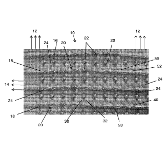
With reference first to Figure 1, this shows a portion 10 of a woven fabric in
plan view, which is formed of a first set of fibres generally referred to by
reference
numeral 12 and a second set of fibres generally referred to by reference
numeral
14. In this example, the first set of fibres 12 constitute the warp of the
weave,
whereas the second set of fibres 14 constitute the weft. It is to be
understood that
the warp and weft directions could be swapped and it is the relative structure
of
the yarns 12, 14 which is relevant not the orientation of manufacture. The
sets of
fibres 12, 14 are formed of a plurality of different types of yarns, as will
become
apparent below. The yarns are preferably in bundles.
The majority of the yarns forming the first and second sets of yarns 12, 14
.. are made of non-conductive material, for which any material known in the
art may
be suitable. These may be of natural material, such as cotton, wool and the
like,
but are preferably made of a synthetic material such as, for example,
polyester,
nylon, viscose or the like, or any combination of synthetic and natural
materials.
The sets of yarns 12, 14 also include a plurality of conductors. In this
embodiment there is provided a plurality of first conductors 16 in the first
set of
yarns 12 and a plurality of second conductors 18 in the second set of yarns
14.
The conductors 16 in the first set, as well as the conductors 18 in the second
set,
CA 03000639 2018-03-29
WO 2017/103562
PCT/GB2016/053693
11
are spaced from one another so that they do not come into physical contact
with
one another under normal usage of the fabric. As will be apparent from Figure
1,
the conductors 16 are disposed substantially parallel to and spaced from one
another in the first direction 12, as are the second conductors 18.
The conductors 16 and 18, as well as the other yarns forming the fabric 10
are all woven into a single or common layer of fabric. In other words, the
structure
does not require two different woven structures, as seen for example in that
woven
structure known in the art as double cloth, or woven and non-woven layers
interposed over one another. The conductors 16, 18 are therefore incorporated
into the structure of the fabric 10 during the weaving process.
The conductors 16, 18 cross one another at a plurality of crossing points
20. At these crossing points 20, the first conductors 16 are located below a
volume of non-conductive yarns hereinafter referred to as a non-conductive
element 24. This volume of non-conductive yarns 24 physically separates the
crossing conductors 16, 18 such that they do not, and in practice cannot, come
into contact with one another and therefore they remain electrically separate
from
one another. The non-conductive element 24 is interposed directly between the
crossing conductors 16 and 18, in what could be described as a linear
arrangement of: conductor - non-conductive element - conductor.
In the example of Figure 1 the fabric also includes a plurality of electrical
connection points 22, in which crossing conductors 16, 18 are in physical
contact
with one another. These electrical connection points 22 form a permanent
electrical connection between two crossing conductors 16, 18, with the
intention
that electrical signals or power can be transferred from one conductor 16 to
the
other conductor 18 and vice versa. This enables the structure to provide a
complex conductive path through the fabric, for directing signals and/or power
to
different locations in the fabric and in practice to different locations in an
article
incorporating the fabric 10. The electrical connection points 22 are formed by
not
having a non-conductive element 24 interposed between the crossing conductors
.. 16,18.
The non-conductive element 24 is formed of one or more yarns of the first
set of yarns 12, which extend generally parallel with the conductive yarns 16.
As
CA 03000639 2018-03-29
WO 2017/103562
PCT/GB2016/053693
12
is described below in detail, the yarn or yarns of the non-conductive element
24
are in practice pressed, biased or moved so as to become disposed over the
adjacent conductor 16 at a crossing point 20, achieved during weaving and by
the
weave structure. As a consequence, the non-conductive elements 24, which act
as electrical insulators, are an integral part of the weave and do not require
any
additional components. The weave structure is also such as to ensure that the
non-conductive yarns forming the element 24 retain this position over time and
even when the fabric 10 is bent or folded.
Figure 3 shows the fabric 10 in enlarged view compared to Figure 1 and
partially folded in the direction of the conductors 18, such that the
structure of the
fabric 10 and the crossing points 20 can better be seen. The non-conductive
elements 24 are, in the preferred embodiment, each formed of two non-
conductive
yarns 30, 32 which typically lie either side of an associated conductor 16 and
are
pulled over the conductor 16 at the crossing point 20 and towards one another
so
as to create a volume of non-conductive material over the conductor 16, in
order to
isolate it from the overlying crossing conductor 18. This is achieved by means
of
yarns passing in the second direction 14.
Specifically, and as is described in further detail below, a crossing
non-conductive yarn 40 of the second set of yarns 14 extends across the yarns
30,
32 at the crossing points 20 and is woven so as to pull the yarns 30, 32
together
and over the conductor 16. In practice, during the weaving process the
conductor
16 is moved out of the plane of the yarns 30, 32, for example by holding the
conductor 16 on a separate heddle or by physically pushing it away as
described
in further detail below, enabling the yarns 30, 32 to be pulled over the
conductor
16. The crossing yarn 40 is arranged to keep the yarns 30 and 32 precisely
over
conductive yarn 16 so as to create the insulating barrier between the yarns 16
and
18.
In the embodiment shown in Figures 1 to 3, the second conductors 18,
extending in the in second direction 14, are woven so as to sit on top of the
crossing yarn 40. This creates a second insulating barrier between the
crossing
conductors 16, 18 and a particularly robust structure which resists short
circuiting
even when the fabric 10 is folded, for example across the warp or across the
weft.
CA 03000639 2018-03-29
WO 2017/103562
PCT/GB2016/053693
13
As can be seen in Figures 1 and 3, the first set of yarns 12 also includes,
for each conductor 18 across each crossing point 20 a pair of tie yarns 50, 52
which act to tie the conductor 18 over the crossing non-conductive yarn 40 of
the
second set of yarns 14 and to hold it in this position in the weave. The
conductors
.. 18 are therefore unable to move within the fabric structure, ensuring that
a proper
electrical separation is retained.
With reference now to Figure 2, this shows the underside of fabric 10, that
is the side opposite that visible in Figures 1 and 3. The conductive yarns 16
can
be seen in Figure 2, whereas the conductive yarns 18 are not visible as they
sit
above the underside surface of the fabric 10. The second set of yarns 14
include
a series of non-conductive crossing yarns 60 which extend over the sections of
conductive yarns 16 exposed in the bottom surface of the fabric 10. There are
also provided sets of third and fourth tie yarns 62, 64 either side of each
conductive yarn 16 and which pass over the crossing yarn 60, thereby to keep
the
conductive yarns 16 firmly in position also on this side of the fabric 10.
The non-conductive tie yarns 50, 52, 62, 64 could in some embodiments be
separate yarns, whereas in other embodiments a common yarn could serve as two
or more of the tie elements 50, 52, 62, 64.
The structure of the preferred embodiment of fabric 10 can be more fully
appreciated from a consideration of Figures 4 to 6, which show cross-sectional
views of the fabric structure 10 of Figures 1 to 3 taken across the warp.
Figure 4 shows a portion of the fabric 10 which is plain weave. Figure 4(a)
shows a cross-section at a first position in the fabric, whereas Figure 4(b)
shows a
cross-section which is a single weft yarn further advanced. This sequence of
.. Figures illustrates the manner in which the fabric 10 is constructed, one
weft yarn
at a time. This is analogous to the manner in which any woven fabric is
constructed in practice.
With reference first to Figure 4(a), there is plurality of non-conductive warp
yarns 101 which extend in direction 12 of the fabric 10 and which
conventionally lie
.. side-by-side in a common plane. The yarns 101 may be multi stranded yarns.
The yarns 12 also include a pair of non-conductive warp yarns 102, which
are equivalent to the yarns 30, 32 inn Figures 1 to 3 and constitute, as will
become
CA 03000639 2018-03-29
WO 2017/103562
PCT/GB2016/053693
14
apparent below, the non-conductive separator element 24 of the fabric 10. Each
of the yarns 102 is treated during weaving as a single yarn. Indeed, the yarns
102
may each be constituted in some embodiments as a single yarn but are
advantageously composed of a bundle of independent yarns or filaments. The
bundle of yarns may or may not be twisted together. As will be apparent from
Figures 4 to 6, it is preferred that the yarns 102 are formed from a greater
number
or strands or filaments than the yarns 101. In some embodiments, the number of
strands or filaments in the yarns 102 may be a multiple of the number of
strands or
filaments in the yarns 101, numbering between two and ten times the number of
yarns. The yarns 102 therefore have a greater volume than the yarns 101. This
is
not an essential characteristic of the yarns 102 as a fabric can be equally
constructed with yarns 102 which are the same as the yarns 101 or even less
voluminous than the yarns 101, but is the preferred form.
Also extending along the warp is a conductive yarn 103, which is equivalent
to the yarns 16 shown in Figures 1 to 3.
A non-conductive weft yarn 104 interlaces with the warp yarns 101, 102,
103 can be seen in the Figure. Another non-conductive weft yarn 105aõ which
can be termed to be on an "alternate footing" to weft yarn 104, interlaces in
a
fashion that is laterally inverted to weft yarn 104.
Figure 4(b) shows a further lateral cross-section of the fabric 10, in which
the plane of cross-section has been advanced in the warp direction, by a
distance
of one weft yarn. Usefully, Figure 4(a) could be viewed as a cross-section of
a
partially constructed fabric, and Figure 4(b) as a similar cross-sectional
view in
which the subsequent non-conductive weft yarn, 105b, has been added.
It will be seen that the subsequent weft yarn 105b is in its own turn
laterally
inverted to weft yarn 104. Weft yarn 105b is therefore similar in interlaced
geometry to weft yarn 105a.
Referring now to Figure 5, this shows a portion of the fabric 10 in which a
conductive weft yarn is introduced. In Figure 5, the desired intent is that
this
conductive weft yarn makes permanent electrical contact with a conductive warp
yarn. This produces the contact points 22 between the conductive yarns 16, 18
of
Figures 1 and 3.
CA 03000639 2018-03-29
WO 2017/103562
PCT/GB2016/053693
Figure 5(a) shows a cross-section of the fabric 10 just prior to the insertion
of the conductive weft yarn 106 (equivalent to the yarns 18 of Figures 1 and
3). It
should be noted that this region of the fabric has a similar plain weave
structure to
that of Figure 4.
5 A non-conductive weft yarn 104a extends in the weft direction, as is the
non-conductive weft yarn 105 that precedes non-conductive weft yarn 104a, and
is
therefore interlaced on the alternate footing to 104a.
In Figure 5(b) the next weft yarn has been inserted, which is a conductive
weft yarn 106. It will be appreciated that the plain weave structure results
in a
10 large contact area 107 between the conductive warp yarn 103 and the
conductive
weft yarn 106.
Figure 5(c) shows the subsequent weft yarn to be inserted, which is a
non-conductive weft yarn 104b on a similar interlace footing to weft yarn
104a.
The weft yarns 104a and 104b serve on either side to hold conductive weft yarn
15 106 in reliable electrical contact with conductive warp yarn 103.
Figure 6 shows the sequence of weft yarn insertions that take place in order
to construct a non-connected crossover point 20 between two conductive yarns
16,18.
Figure 6a shows the initial plain weave construction, similar to that of
Figures 4 and 5, and which includes conductive warp yarn 103 (equivalent to
the
conductive yarns 16 of Figures 1 to 3), a bundle of non-conductive warp yarns
102a, and non-conductive weft yarns 104 and 105 on alternating interlace
footing.
Figure 6b shows the insertion of a subsequent non-conductive weft yarn
108. The weft yarn 108 is not inserted with a plain weave interlace but
instead is
"floated" over three effective warp yarns, that is the conductive warp yarn
103 and
the two bundles of non-conductive warp yarns 102a (these bundles being each
treated as single yarns for the purposes of the weaving process). The floated
weft
yarn 108 serves to compress the two bundles of warp yarns 102a together, into
a
single mass of yarns 102b. Additionally, as this compressive force is applied
by
floated weft yarn 108 onto the bundles of warp yarns 102a, the increased local
tension on the prior weft yarn 105 tends to deflect the conductive warp yarn
103
away from the floated weft yarn 108. This is downwards in this illustrative
example.
CA 03000639 2018-03-29
WO 2017/103562
PCT/GB2016/053693
16
The resulting, and desired, geometry is one in which the bundles of warp
yarns 102a coalesce into a single bundle 102b, which is additionally forced
into a
position directly between the conductive warp yarn 103 and the floated weft
yarn
108.
It is possible and sometimes desirable to repeat the insertion of additional
floated weft yarns 108 at this point during construction, using a similar
interlace
structure. Such additional floated weft yarns can serve to enhance the desired
geometry, by increasing the compressive force upon the bundles 102a and
increasing the tensile force on prior weft yarn 105 which in turn exerts a
greater
downwards force upon the conductive warp yarn 103.
Figure 6(c) shows the insertion of a subsequent conductive weft yarn 109,
which equivalent to one of the yarns 18 of Figures 1 to 3. Conductive weft
yarn
109 is also floated over a number of warp yarns, in similar fashion to the
preceding
weft yarn 108. However, it is advantageous that the conductive weft yarn 109
is
floated over a greater number of warp yarns than the preceding weft yarn 108.
The arrangement could be said to use spacer yarns 101a between the floated
yarn
108 and each conductive weft yarn 109. The floated section of the conductive
yarn 109 is therefore made looser than the floated section of the preceding
weft
yarn 108, because it is placed under less tension and is more free to deflect.
The
longer, looser float of the conductive yarn 109 tends therefore to sit in a
position
that is higher from the plane of the fabric than the preceding float.
Figure 6(d) shows the insertion of another non-conductive weft yarn 110,
which has a similar interlace geometry to weft yarn 108, and a correspondingly
shorter float to that of conductive weft yarn 109. The shorter, tighter floats
of the
non-conductive weft yarns 108 and 110 either side of the conductive yarn float
tend to push beneath the conductive yarn float and lift it further away from
the
plane of the fabric.
It is a desirable outcome that the non-conductive floats 108 and 109 are
brought together into contact beneath the conductive yarn float 109 and
coalesce,
in order to create an additional layer of physical barrier between the
conductive
warp yarn 103 and conductive weft yarn 109. This desirable outcome may be
enhanced by increasing the length of float of the conductive weft yarn 109
relative
CA 03000639 2018-03-29
WO 2017/103562
PCT/GB2016/053693
17
to the length of float of the non-conductive weft yarns 108 and 110. However,
if
the conductive weft yarn floats are excessively long they can become too loose
and risk being damaged or making inadvertent electrical contact with other
portions of the conductive warp yarn or any adjacent conductive weft yarns.
The
difference should therefore be kept within reasonable limits, which the
skilled
person will be able to determine readily.
The preferred method also enhances this outcome, and most effectively, by
a technique referred herein as "cramming", wherein the weaving loom inserts a
greater number of weft yarns into a given length of fabric, thereby increasing
the
"pick-density" locally to the crossover point. This can be achieved in the
preferred
embodiment by programing a positive-drive weaving loom to increase the
"pick-rate" in the region of a crossover point. On direct-(geared-)drive
weaving
looms cramming may be achieved by halting the take-up momentarily, and/or
performing multiple beat operations with the loom's reed for each weft
insertion.
The desirable outcome may further be enhanced by reducing the weft
insertion tension of the conductive yarn 103 relative to the adjacent
non-conductive weft yarns 108 and 110. This may be influenced by various
means, directly and indirectly, such as selecting yarns for their relative
elasticity,
varying the timing of weft insertion, or varying the shed geometry, according
to the
type and model of weaving loom employed.
Another enhancement of some embodiments increases the number of
floated non-conductive weft yarns 108 and 110. It should be borne in mind that
increasing the number of floated weft yarns 108 and 110 also results in an
increase in the length of float of the conductive warp yarn 103 which, if
excessive,
can cause the conductive warp yarn 103 to become too loose and risk damage or
inadvertent short circuits with other portions of the conductive weft yarn or
any
adjacent conductive warp yarns. The risk of such short circuiting can be
reduced
or avoided by the insertion of a non-conductive weft yarn 111, shown in Figure
6(e) (and equivalent to the non-conductive yarn 60 visible in Figure 2). This
weft
yarn 111 serves to "pin" the float of the conductive warp yarn 103 into
position and
prevent it from becoming too loose. In some embodiments, if the pinning weft
yarn
111 is excluded, there can be the risk of inadvertent short circuits due to
CA 03000639 2018-03-29
WO 2017/103562
PCT/GB2016/053693
18
movement of the float of the conductive warp yarn 103, which can occur
particularly in fabrics with large diameter conductive warp yarns and/or where
multiple conductive warp yarns are desired to be closely spaced together. The
pinning weft yarn 111 is therefore an advantageous feature in enabling the
creation of fabrics that are robustly capable of carrying high currents and/or
which
exhibit a high density of independent conductive paths, both within a smaller
area
of fabric.
Figure 6(f) shows the insertion of the subsequent non-conductive weft yarn
112, which is interlaced according once more to plain weave. The interlace
footing
of weft yarn 112 is similar to that of weft yarn 105. In similar fashion to
weft yarn
105, the local tension imparted by weft yarn 112 on the conductive warp yarn
103
tends to deflect the conductive warp yarn 103 away from the floated weft yarns
108, 109 and 110.
To be noted also is that with the reintroduction of a plain weave interlace
for
this weft yarn 112, the bundles of non-conductive warp yarns 102c are brought
apart once more.
Figure 6(g) shows the insertion of the subsequent non-conductive weft yarn
113. This weft yarn 113 is interlaced according to plain weave, on the
alternate
footing to the prior plain weave weft 112. It can be seen that the bundles of
warp
yarns 102d are fully separated at this point, and also that the conductive
warp yarn
103 is returned to a median position within the plane of the fabric.
Continued weaving of the fabric may now commence, with the insertion of
plain weave non-conductive weft yarns according to the interlace fashions of
weft
yarns 104 and 105 as appropriate.
The sequence of weft insertions shown throughout Figure 6 is merely
illustrative of one preferred embodiment. In practice, variations of float
length,
multiple instances of weft insertion, and variations of weft sequencing may
all be
employed in combination on weft insertions 105, 108, 109, 110, 111, 112 and
113.
This variation is according to and dictated by factors such as diameter of
yarns,
permissible area of fabric, permissible thickness of fabric, distance between
adjacent conductive warp and/or weft yarns.
CA 03000639 2018-03-29
WO 2017/103562
PCT/GB2016/053693
19
Figure 7 is a schematic plan view of a portion of fabric woven in accordance
with the sequences shown in Figures 4 to 6 and as taught herein. In the
portion a
permanently separate crossing point 20 can be seen, as can a permanently
connected crossing point 22. The bunching of the yarns 30,32 and of the
cross-yarns 40 is also depicted. As can be seen, the at least two non-
conductive
yarns 30, 32 extending on opposing sides of the first conductor are laterally
biased
so as to be deflected over the first conductor at the crossing point 22.
Referring now to Figure 8, this shows a representation of a preferred
embodiment of weaving apparatus, configured in order to produce a fabric
structure as taught herein. The weaving apparatus shown is a dobby loom,
although a jacquard loom may also be employed. Note also that additional
rollers
for guiding the warp yarns, such as a breast beam, or whip or back beam, are
not
shown in the diagram, for clarity.
With reference to Figure 8, 102 is the non-conductive warp yarn or bundle
of non-conductive warp yarns that lies adjacent to the conductive warp yarn
103.
Note that this warp yarn or yarns 102 is threaded through heddles 125, which
are
attached to a harness or shaft 124, which is independent from those of the
remaining non-conductive warp yarns 101. A warp beam 121 carries the
non-conductive warp yarns. Advantageously, but not essentially, this warp beam
121 is positively-driven by an independently controllable motor, such that the
tension placed upon the non-conductive warp yarns may be monitored and
controlled.
A warp beam 122 carries the conductive warp yarn 103. Advantageously,
but not essentially, this warp beam 122 that is separate from the warp beam
121
that carries the non-conductive warp yarns 101 and 102. This advantageous
feature of the weaving apparatus, proffered by the use of a twin-beam loom,
aids
the warping-up and subsequent weaving of conductive and non-conductive warp
yarns that are substantially dissimilar in terms of diameter and elasticity.
Also advantageously, but not essentially, this warp beam 122 is
positively-driven by an independently controllable motor, such that the
tension
placed upon the conductive warp yarns may be monitored and controlled,
CA 03000639 2018-03-29
WO 2017/103562
PCT/GB2016/053693
particularly in relative proportion to that tension placed upon the non-
conductive
warp yarns.
It is also possible for some or all of the warp yarns 101, 102 and 103, that
warp beams are not employed, and that some or all of the warp yarns are
instead
5 .. fed into the weaving apparatus by means of bobbins, reels and/or creels,
preferably with some mechanism for the tension control of the yarn as it is
fed.
A conductive warp yarn 103 is shown, fitted on the warp beam 102. A
harness, or shaft, 123 moves the heddles through which the conductive warp
yarn
is threaded. Note that this harness 123 is independent from the harnesses 124,
10 126 and 127 that carry the non-conductive warp yarns 101.
A harness, or shaft, 124 moves the heddles through which the
non-conductive warp yarns, or bundles of non-conductive warp yarns, adjacent
to
the conductive warp yarn are threaded. Note that this harness 124 is
independent
from the harnesses 126 and 127, that carry the remainder of the non-conductive
15 warp yarns, and from harness 123 that carries the conductive warp yarn
103.
A heddle 125, through which a single warp yarn is threaded, is raised or
lowered by a particular harness or shaft. Note that multiple heddles may be
used
on a single shaft in the instance that multiple yarns or fibres or filaments
are
employed in concert to constitute a single warp yarn, such as in the cases
that the
20 non-conductive warp yarns 102 are bundles of yarns. Similarly, multiple
heddles
may be used on a single shaft in the case that multiple warp yarns are
employed
in concert to expand the width of the crossover structure and the length of
the weft
floats.
Reference numeral 101 depicts a non-conductive warp yarn that is not
adjacent to a conductive warp yarn.
Harnesses, or shafts, 126 and 127 move the heddles through which the
non-conductive warp yarns 101, that are not adjacent to the conductive warp
yarn
103, are threaded. Shafts 126 and 127 are preferably each threaded with
roughly
half of the non-conductive warp yarns 101, in alternating fashion, such that
these
shafts, in concert with shafts 123 and 124, may form a plain weave. An
alternative
conventional weave structure, such as hopsack or twill, may be employed, in
CA 03000639 2018-03-29
WO 2017/103562
PCT/GB2016/053693
21
which instance these harnesses 126 and 127 may be threaded differently,
accordingly.
A reed 128 is provided, which may advantageously be threaded, or sleyed,
with multiple warp yarns in certain dents in order to increase the density of
warp
yarns in the vicinity of a conductive warp yarn.
A weft yarn 129 can be seen in the process of being inserted by means of a
shuttle, which is only present where weaving is performed on a projectile
loom.
Weaving of the fabric may also be performed on a rapier loom or air-jet loom.
Advantageously, a rapier loom is employed, for its superior ability in general
to
manipulate heavier and/or thicker weft yarns.
The woven fabric 131 can be seen at the end of the weaving process, being
held by a cloth roller 132, otherwise known as a cloth beam or take-up beam.
Advantageously, the cloth roller 132 is positively-driven or geared such that
the
speed of take-up of the finished fabric 131 may be controlled during the
weaving
process, preferably under the control of the same software program that
sequences the lifting of the shafts. Consequently, the pick or weft density of
the
fabric 131 may advantageously be controlled and varied during weaving, for
instance in order to increase the density of weft yarns in the vicinity of a
crossover
point.
The important features of the fabric and method of construction of the fabric
include but are not limited to:
a) a non-conductive warp yarn, or yarns, or bundles of yarns, illustrated by
102, that are disposed to one or either side of a conductive warp yarn or
yarns, the
purpose of which non-conductive yarn(s) is to become forced into an interposed
position between that conductive warp yarn(s) 103 and a crossing conductive
weft
yarn or yarns 109;
b) a non-conductive weft yarn or yarns, illustrated by 108 and 110, the
purpose of which yarn(s) is to float over the conductive warp yarn(s) 103 and
adjacent non-conductive warp yarns 102 in order to effect the forcing together
and
interposed positioning of said non-conductive warp yarns 102;
22
C) it is a further purpose of the non-conductive weft yarn(s), illustrated by
108 and 110, to become additionally interposed between a conductive warp
yarn(s) 103 and a crossing conductive weft yarn(s) 109;
d) a non-conductive weft yarn or yarns, illustrated by 111, the purpose of
which is to pin the floated portion of the conductive warp yarn(s) 103 into
position,
and avoid this float becoming too long and/or loose.
The embodiments described above make use of a pair of yarns or yarn
bundles 30, 32, 102a to form the non-conductive element 24 of the fabric 10.
However, in other embodiments, a single yarn or bundle of yarns may be used
and
trained to overlie the conductive yarn 16, 103. In other embodiments, more
than
two yarns or bundles or yarn may be used but this is not preferred.
The conductors of the fabric will typically be of low/negligible resistivity
for
data transfer and power supply purposes. Other embodiments may use one or
more resistive conductive elements in a structure as that taught herein, for
instance for heating purposes.
The fabrics disclosed herein can be used in a variety of different
applications including for wearable apparel such as jackets, coats, vests,
trousers,
capes, as well as helmets, gloves and the like. The applications are not
limited to
wearable items, but also generally to all of those items where woven textile
compositions are advantageous, and the addition of electrically conductive
function therein might also be advantageous, such as in furnishings,
carpeting,
tenting, vehicle upholstery, luggage, hard composite structures, medical
dressings,
structural textiles and so on. The fabrics disclosed herein may also offer
advantages over more conventionally constructed electrical circuits, such as
printed circuit boards, flexible circuit boards, cable harnesses and wiring
looms,
due to the fabrics' flexibility, robustness, low-profile, light weight and
automated
means of manufacture.
While the above description provides examples of the embodiments, it will
be appreciated that some features and/or functions of the described
embodiments
are susceptible to modification without departing from the spirit and
principles of
operation of the described embodiments. Accordingly, what has been described
above has been intended to be illustrative of the embodiments and non-
limiting,
Date Recue/Date Received 2022-06-14
23
and it will be understood by persons skilled in the art that other variants
and
modifications may be made without departing from the scope of the embodiments
as defined in the claims appended hereto.
Date Recue/Date Received 2022-06-14