Note: Descriptions are shown in the official language in which they were submitted.
CA 03000641 2018-03-29
WO 2017/078674 PCT/US2015/058648
THREE-DIMENSIONAL GEOMECHANICAL MODELING OF CASING
DEFORMATION FOR HYDRAULIC FRACTURING TREATMENT DESIGN
FIELD OF THE DISCLOSURE
The present disclosure relates generally to the design of hydraulic fracturing
treatments for stimulating hydrocarbon production from subsurface reservoirs,
and
particularly, to design techniques for mitigating casing failure during
hydraulic fracturing
treatments.
BACKGROUND
io In
the oil and gas industry, a well that is not producing as expected may need
stimulation to increase the production of subsurface hydrocarbon deposits,
such as oil and
natural gas. Hydraulic fracturing has long been used as a major technique for
well
stimulation. The rapid development of unconventional resources in recent years
has led to
a renewed interest in hydraulic fracturing, and multistage hydraulic
fracturing in particular.
is
Examples of such unconventional resources include, but are not limited to, oil
and/or
natural gas trapped within tight sand, shale, or other type of impermeable
rock formation.
A multistage hydraulic fracturing operation may involve drilling a horizontal
wellbore and
applying a series of stimulation injections along the wellbore over multiple
stages.
A key factor to the success of such a hydraulic fracturing operation is
maintaining
20
casing integrity along the wellbore during each stage of the operation.
Significant casing
deformation in a section of the wellbore can hinder or even stop the progress
of the
hydraulic fracturing operation altogether. For example, such casing
deformation may
prevent the removal of bridge plugs or other operational work that may need to
be
performed for that section before the operation can proceed to other sections
of the
25
wellbore. Consequently, several well sections or even the entire well may have
to be
abandoned due to any casing deformation that may occur before all stages of
the hydraulic
fracturing operation have been completed.
Therefore, an effective design for a multistage hydraulic fracturing operation
should
account for the potential casing deformation that may occur during different
stages of the
30
operation. Such an effective hydraulic fracturing design may then be used to
mitigate the
chances of a costly failure in the casing during the actual operation.
1 of 48
CA 03000641 2018-03-29
WO 2017/078674 PCT/US2015/058648
BRIEF DESCRIPTION OF THE DRAWINGS
FIG. 1 is a diagram of an illustrative well system for hydraulically
fracturing a
subterranean formation.
FIGS. 2A and 2B are different views of an asymmetric distribution of fractures
induced by hydraulic fracturing within a subterranean formation relative to a
trajectory of a
wellbore drilled through the formation.
FIG. 3 is a diagram illustrating the location of casing deformation caused by
hydraulic fracturing along the trajectory of a wellbore.
FIG. 4 is a diagram illustrating different stages of a hydraulic fracturing
treatment
design along a planned trajectory of a horizontal wellbore within a subsurface
formation.
FIG. 5 is a flowchart for an illustrative process of modeling casing
deformation for
improved hydraulic fracturing treatment design and analysis.
FIG. 6 is a graph showing different injection pressures during a stage of a
multistage hydraulic fracturing treatment.
FIG. 7 is a diagram of an illustrative three-dimensional (3D) global model of
a
subsurface formation.
FIG. 8 is a diagram of an illustrative 3D sub-model of a portion of the
subsurface
formation modeled in FIG. 7.
FIG. 9 is a diagram showing a cross-sectional view of a portion of the 3D sub-
model of FIG. 8 for estimating casing deformation along a planned trajectory
of a
horizontal wellbore.
FIGS. 10A and 10B are 3D meshes illustrating estimated values of casing
deformation with relatively high quality cementing material along the
horizontal wellbore.
FIG. 11A and 11B are 3D meshes illustrating estimated values of casing
deformation with relatively low quality cementing material along the
horizontal wellbore.
FIG. 12 is a block diagram of an illustrative computer system in which
embodiments of the present disclosure may be implemented.
2 of 48
CA 03000641 2018-03-29
WO 2017/078674 PCT/US2015/058648
DESCRIPTION OF ILLUSTRATIVE EMBODIMENTS
Embodiments of the present disclosure relate to modeling casing deformation
for
improved hydraulic fracturing design. While the present disclosure is
described herein
with reference to illustrative embodiments for particular applications, it
should be
understood that embodiments are not limited thereto. Other embodiments are
possible, and
modifications can be made to the embodiments within the spirit and scope of
the teachings
herein and additional fields in which the embodiments would be of significant
utility.
Further, when a particular feature, structure, or characteristic is described
in connection
with an embodiment, it is submitted that it is within the knowledge of one
skilled in the
io relevant art to effect such feature, structure, or characteristic in
connection with other
embodiments whether or not explicitly described.
It would also be apparent to one of skill in the relevant art that the
embodiments, as
described herein, can be implemented in many different embodiments of
software,
hardware, firmware, and/or the entities illustrated in the figures. Any actual
software code
is with the specialized control of hardware to implement embodiments is not
limiting of the
detailed description. Thus, the operational behavior of embodiments will be
described with
the understanding that modifications and variations of the embodiments are
possible, given
the level of detail presented herein.
In the detailed description herein, references to "one embodiment," "an
20 embodiment," "an example embodiment," etc., indicate that the embodiment
described
may include a particular feature, structure, or characteristic, but every
embodiment may not
necessarily include the particular feature, structure, or characteristic.
Moreover, such
phrases are not necessarily referring to the same embodiment. Further, when a
particular
feature, structure, or characteristic is described in connection with an
embodiment, it is
25 submitted that it is within the knowledge of one skilled in the art to
implement such
feature, structure, or characteristic in connection with other embodiments
whether or not
explicitly described.
As will be described in further detail below, embodiments of the present
disclosure
utilize geomechanical modeling techniques to estimate the location and amount
of casing
30 deformation that may occur during one or more stages of a multistage
hydraulic fracturing
treatment operation within a subsurface formation. In one or more embodiments,
three-
dimensional (3D) models of the subsurface formation may be used to simulate
the effects
3 of 48
CA 03000641 2018-03-29
WO 2017/078674 PCT/US2015/058648
of hydraulic fracturing injection loads on the casing in one or more sections
of a horizontal
or deviated wellbore within the formation. Each section of the wellbore may
correspond
to, for example, a stage of the multistage hydraulic fracturing treatment. The
results of the
simulation may then be used to determine a maximum threshold value of safe
hydraulic
fracturing fluid injection pressures that can be used during a particular
stage of the
treatment without causing significant casing deformation along the wellbore.
Such a
maximum threshold value may represent, for example, the maximum hydraulic
fracturing
injection load that the casing in that section of the wellbore can withstand
before
undergoing significant casing deformation.
io
Illustrative embodiments and related methodologies of the present disclosure
are
described below in reference to FIGS. 1-12 as they might be employed, for
example, in a
computer system for modeling a subsurface formation and the effects of
hydraulic
fracturing treatment operations along a planned trajectory of a horizontal
wellbore within
the formation. In one or more embodiments, the computer system may be used to
generate
is the
aforementioned 3D models of the subsurface formation as part of a workflow for
estimating casing deformation under different fluid injection pressures during
the design
and implementation of a multistage hydraulic fracturing treatment along the
planned
wellbore trajectory. Other features and advantages of the disclosed
embodiments will be or
will become apparent to one of ordinary skill in the art upon examination of
the following
20
figures and detailed description. It is intended that all such additional
features and
advantages be included within the scope of the disclosed embodiments. Further,
the
illustrated figures are only exemplary and are not intended to assert or imply
any limitation
with regard to the environment, architecture, design, or process in which
different
embodiments may be implemented.
25 FIG.
1 is a diagram illustrating an example of a well system 100 for performing a
multistage hydraulic fracturing treatment of a subsurface formation. As shown
in the
example of FIG. 1, well system 100 includes a wellbore 102 in a subterranean
region 104
beneath a surface 106 of the formation. The example wellbore 102 shown in FIG.
1
includes a horizontal wellbore. However, it should be appreciated that
embodiments are
30 not
limited thereto and that well system 100 may include any combination of
horizontal,
vertical, slant, curved, and/or other wellbore orientations. The subterranean
region 104
may include a reservoir that contains hydrocarbon resources, such as oil,
natural gas, and/or
4 of 48
CA 03000641 2018-03-29
WO 2017/078674 PCT/US2015/058648
others. For example, the subterranean region 104 may be a rock formation
(e.g., shale,
coal, sandstone, granite, and/or others) that includes hydrocarbon deposits,
such as oil and
natural gas. In some cases, the subterranean region 104 may be a tight gas
formation that
includes low permeability rock (e.g., shale, coal, and/or others). The
subterranean region
104 may be composed of naturally fractured rock and/or natural rock formations
that are
not fractured to any significant degree.
Well system 100 also includes a fluid injection system 108 for injecting
hydraulic
fracturing fluid into the subterranean region 104 over multiple sections 118a,
118b, 118c,
118d, and 118e (collectively referred to as "sections 118") of the wellbore
102, as will be
io described in further detail below. Each of the sections 118 may
correspond to, for
example, a different stage or interval of the multistage hydraulic fracturing
injection
treatment. The boundaries of the respective sections 118 and corresponding
treatment
stages/intervals along the length of the wellbore 102 may be delineated by,
for example, the
locations of bridge plugs, packers and/or other types of equipment in the
wellbore 102.
Additionally or alternatively, the sections 118 and corresponding treatment
stages may be
delineated by particular features of the subterranean region 104. Although
five sections are
shown in FIG. 1, it should be appreciated that any number of stages may be
used as desired
for a particular implementation. Furthermore, each of the sections 118 may
have different
widths or may be uniformly distributed along the wellbore 102.
As shown in FIG. 1, injection system 108 includes an injection control
subsystem
111, a signaling subsystem 114 installed in the wellbore 102, and one or more
injection
tools 116 installed in the wellbore 102. The injection control subsystem 111
can
communicate with the injection tools 116 from a surface 110 of the wellbore
102 via the
signaling subsystem 114. Although not shown in FIG. 1, injection system 108
may include
additional and/or different features for implementing the modeling and casing
deformation
estimation techniques disclosed herein. For example, the injection system 108
may include
any number of computing subsystems, communication subsystems, pumping
subsystems,
monitoring subsystems, and/or other features as desired for a particular
implementation.
During each stage of the hydraulic fracturing treatment, the injection system
108
may alter stresses and create a multitude of fractures in the subterranean
region 104 by
injecting hydraulic fracturing fluid into the surrounding rock formation along
a portion of
the wellbore 102 (e.g., along one or more of sections 118). The fluid may be
injected
5 of 48
CA 03000641 2018-03-29
WO 2017/078674 PCT/US2015/058648
through any combination of one or more valves of the injection tools 116. The
injection
tools 116 may include numerous components including, but not limited to,
valves, sliding
sleeves, ports, and/or other features that communicate fluid from a working
string installed
in the wellbore 102 into the subterranean region 104. The flow of fluid into
the
subterranean region 104 during one or more stages of the hydraulic fracturing
treatment
may be controlled by the configuration of the injection tools 116. For
example, the valves,
ports, and/or other features of the injection tools 116 can be configured to
control the
location, rate, orientation, and/or other properties of fluid flow between the
wellbore 102
and the subterranean region 104. The injection tools 116 may include multiple
tools
io coupled by sections of tubing, pipe, or another type of conduit. The
injection tools may be
isolated in the wellbore 102 by packers or other devices installed in the
wellbore 102.
In some implementations, the injection system 108 may be used to create or
modify
a complex fracture network in the subterranean region 104 by injecting fluid
into portions
of the subterranean region 104 where stress has been altered. For example, the
complex
is fracture network may be created or modified after an initial injection
treatment has altered
stress by fracturing the subterranean region 104 at multiple locations along
the wellbore
102. After the initial injection treatment alters stresses in the subterranean
formation, one
or more valves of the injection tools 116 may be selectively opened or
otherwise
reconfigured to stimulate or re-stimulate specific intervals of the
subterranean region 104,
20 taking advantage of the altered stress state to create complex fracture
networks. In some
cases, the injection system 108 may inject fluid simultaneously for multiple
intervals and
sections 118 of wellbore 102.
In one or more embodiments, the injection tools 116 may include micro-seismic
equipment, tiltmeters, pressure meters and/or other equipment to gather
information
25 relating to the extent of fracture growth and complexity during the
hydraulic fracturing
injection treatment. For example, the injection system 108 may utilize real
time fracture
mapping, real time fracturing pressure interpretation, and other data analysis
techniques to
monitor stress fields around hydraulic fractures based on the information
gathered by the
injection tools 116. Based on the monitoring, the injection system 108 may
selectively
30 control the valves of injection tools 116 in order to achieve desirable
fracture geometries or
help facilitate complex fracture growth. In one or more embodiments, the
valves may also
be selectively controlled to adjust the fluid injection pressure for one or
more stages of the
6 of 48
CA 03000641 2018-03-29
WO 2017/078674 PCT/US2015/058648
hydraulic fracturing injection treatment in order to prevent or mitigate any
casing
deformation that may occur along a trajectory of wellbore 102 within the
subsurface
formation, as will be described in further detail below.
The operation of the injection tools 116 may be controlled by injection
control
subsystem 111. The injection control subsystem 111 may include, for example,
data
processing equipment, communication equipment, and/or other systems that
control
injection treatments applied to the subterranean region 104 through the
wellbore 102. The
injection control subsystem 111 may receive, generate and/or modify an
injection treatment
plan that specifies properties of an injection treatment to be applied to the
subterranean
io region 104. The injection control subsystem 111 may initiate control
signals to configure
the injection tools 116 and/or other equipment (e.g., pump trucks, etc.) to
execute aspects
of the injection treatment plan. The injection control subsystem 111 may
receive data
collected from the subterranean region 104 and/or another subterranean region
by sensing
equipment, and the injection control subsystem 111 may process the data and/or
otherwise
is use the data to select and/or modify parameters of an injection
treatment to be applied to
the subterranean region 104. Accordingly, the injection control subsystem 111
may initiate
additional control signals to reconfigure the injection tools 116 and/or other
equipment
based on selected and/or modified parameters.
The signaling subsystem 114 shown in FIG. 1 transmits signals from the
wellbore
20 surface 110 to one or more injection tools 116 installed in the wellbore
102. For example,
the signaling subsystem 114 may transmit hydraulic control signals, electrical
control
signals, and/or other types of control signals. The control signals may
include control
signals initiated by the injection control subsystem 111. The control signals
may be
reformatted, reconfigured, stored, converted, retransmitted, and/or otherwise
modified as
25 needed or desired en route between the injection control subsystem 111
(and/or another
source) and the injection tools 116 (and/or another destination). The signals
transmitted to
the injection tools 116 may control the configuration and/or operation of the
injection tools
116. Examples of different ways to control the operation of each of the
injection tools 116
include, but are not limited to, opening, closing, restricting, dilating,
repositioning,
30 reorienting, and/or otherwise manipulating one or more valves of the
tool to modify the
manner in which fluid is communicated into the subterranean region 104.
7 of 48
CA 03000641 2018-03-29
WO 2017/078674 PCT/US2015/058648
In one or more embodiments, the combination of injection valves of the
injection
tools 116 may be configured or reconfigured at any given time during the
injection
treatment. For example, the sequence of valve configurations can be
predetermined as part
of a treatment plan prior to implementation or adjusted in real time based on
information
gathered during the actual implementation of the treatment plan.
In one or more embodiments, the injection control subsystem 111 may be used to
adjust the fluid injection pressure or rate for different stages of the
hydraulic fracturing
treatment in real time as the treatment plan is implemented. For example, the
fluid
injection pressure may be adjusted after one or more stages of the hydraulic
fracturing
io treatment to prevent or mitigate potential casing deformation during
later stages of the
hydraulic fracturing treatment. In one or more embodiments, the injection
control
subsystem 111 may be used to estimate the location and extent of any casing
deformation
that may occur along the planned trajectory of the wellbore 102 under
different hydraulic
fracturing injection pressures. As will be described in further detail below,
such casing
is deformation may be estimated based on a simulation of the effects of
hydraulic fracturing
injection treatment using 3D models of the subsurface formation. In one or
more
embodiments, the 3D models of the formation may be dynamically updated based
on
information gathered by the system 108 in real-time during one or more stages
of the
hydraulic fracturing treatment. The updated 3D models may then be used as part
of a
20 workflow for estimating the casing integrity and potential points of
casing deformation that
may occur along the wellbore trajectory planned for later treatment stages.
Examples of casing deformation that may occur along a wellbore trajectory are
shown in FIGS. 2A, 2B, 3 and 4. It is assumed for purposes of the examples
shown in each
of FIGS. 2A, 2B, 3 and 4 that the wellbore trajectories and locations of
hydraulic fracturing
25 induced fractures and casing deformations along the respective wellbore
trajectories are
based on relevant measurements and data acquired during various stages of a
multistage
hydraulic fracturing treatment to stimulate the production of hydrocarbon
resources, such
as oil and/or natural gas, from subsurface formations.
FIGS. 2A and 2B are plot graphs illustrating different views of a horizontal
30 wellbore trajectory and the locations of fractures induced by hydraulic
fracturing injection
within a subsurface formation. The subsurface formation may be, for example, a
shale or
other type of low permeability rock formation for which a hydraulic fracturing
injection
8 of 48
CA 03000641 2018-03-29
WO 2017/078674 PCT/US2015/058648
treatment is needed to stimulate the production of unconventional oil and/or
natural gas
resources from the formation. The locations of the hydraulic fracturing
induced fractures in
FIGS. 2A and 2B may be based on, for example, micro-seismic data acquired for
different
points within the formation. Such data may be acquired by, for example,
downhole
equipment, e.g., various measurement devices or sensors, disposed within an
offset well
202, as shown in FIG. 2A. For example, sensors integrated within a drill
string assembly
disposed within well 202 may be used to acquire the micro-seismic data over a
number of
hydraulic fracturing treatment stages performed along multiple sections of the
wellbore.
In FIG. 2A, a lateral view 200A of a wellbore trajectory 210 shows that the
io hydraulic fracturing induced fractures are distributed within
substantially planar areas of
the formation on opposite sides of the wellbore trajectory. In FIG. 2B, an
overhead view
200B of the wellbore trajectory 210 also shows that the distributions of
hydraulic fracturing
induced fractures within the formation areas on either side are asymmetric
relative to the
wellbore trajectory. In particular, the overhead view of FIG. 2B shows that
the majority of
is fractures are located in an area of the formation on one side of the
wellbore trajectory, e.g.,
to the west of the wellbore trajectory. Therefore, it may be assumed that the
distribution of
natural fractures within the formation follow a similar asymmetric pattern
relative to the
wellbore trajectory.
In addition to the asymmetric distribution of hydraulic fracturing induced
fracture
20 locations within the surrounding formation, FIG. 2B also shows a
location 212 of
significant casing deformation in a section of the horizontal wellbore toward
the toe or
leading end of the wellbore trajectory 210 within the formation. The location
212 and
amount of the casing deformation may have been measured using, for example,
downhole
sensors or other measurement devices used to measure casing integrity or
stress under
25 hydraulic fracturing injection loads for the particular section of the
wellbore during a
corresponding stage of the hydraulic fracturing treatment. Such casing
deformation may
hinder or prevent the removal of any bridge plugs that were placed in the
wellbore
following perforation and fluid injection stimulation during the hydraulic
fracturing
treatment, as shown in FIG. 3.
30 FIG. 3 is a diagram illustrating a view 300 of a wellbore trajectory
310. In the
example shown in FIG. 3, casing deformation due to hydraulic fracturing
injection pressure
occurs at a location 312 along the wellbore trajectory. The casing deformation
at location
9 of 48
CA 03000641 2018-03-29
WO 2017/078674 PCT/US2015/058648
312 may prevent the removal of a bridge plug 315. Such casing deformation may
therefore
prevent any remaining stages of the hydraulic fracturing treatment in this
example from
being performed. In contrast with FIGS. 2A and 2B, the location of hydraulic
fracturing
induced casing deformation along the horizontal wellbore trajectory shown in
the example
of FIG. 3 is near the heel or trailing end of the trajectory within the
formation.
FIG. 4 is a diagram illustrating different stages of a hydraulic fracturing
(HF)
treatment design 400 along a planned trajectory of a horizontal wellbore
within a
subsurface formation. The subsurface formation may be, for example, tight gas
formation,
e.g., a coal, shale, or other type of rock formation, which includes
unconventional
io hydrocarbon resources. While a total of twelve stages are shown in FIG.
4, it should be
appreciated that embodiments are not limited thereto and that any number of
stages may be
used for the hydraulic fracturing treatment design. Similar to FIG. 3, the
casing
deformation in FIG. 4 occurs at a location 412 in a section of the wellbore
near the heel of
the wellbore trajectory corresponding to a stage 11 of the hydraulic
fracturing treatment.
is As shown in FIG. 4, there is an asymmetric distribution of formation
thickness relative to
the wellbore trajectory at the heel in this section. Although the thickness of
the formation
area above the wellbore trajectory in this section increases with measured
depth, this
thickness remains relatively smaller than that of the formation area below.
The above-described examples of FIGS. 2A, 2B, 3 and 4 are illustrative of the
20 following three major factors impacting casing deformation under
hydraulic fracturing
injection loads: (1) hydraulic fracturing fluid injection pressure and/or
injection rate; (2)
imperfections of cementing rings around the casing; and (3) asymmetric
distribution of
fractures caused by hydraulic fracturing injection along an axis of the
casing. Of these
three major factors, the amount of hydraulic fracturing injection pressure may
be the
25
primary cause of significant casing deformation along the wellbore. Also,
any
imperfections, gaps, or any lack of uniformity in the cementing material
distributed around
the casing may lead to non-uniform hydraulic fracturing injection loads that
exacerbate
deformation of the casing under hydraulic fracturing injection. Such
imperfections may be
due to the quality of the cementing material that forms the ring or the
quality of cementing
30 process that was used to distribute the material around the casing when
the ring was
formed. An asymmetric distribution of hydraulic fracturing induced fractures,
the third
major factor affecting casing deformation in the wellbore, may be due to an
asymmetric
of 48
CA 03000641 2018-03-29
WO 2017/078674 PCT/US2015/058648
distribution of natural fractures within the subsurface formation or other
structural factors
related to the wellbore and casing geometry. For example, areas of the
formation where the
density of natural fractures is relatively high tend to have relatively high
permeability and
relatively low formation strength. Such areas may therefore provide favorable
conditions
for the development and propagation of fractures within the formation.
Further, since the
casing geometry at the heel of the wellbore is in a curved shape, the
distribution of
fractures generated within the formation by any stages of the hydraulic
fracturing injection
treatment performed near the heel tend to be asymmetric to the curved casing.
While there may be other factors, such as mini-fault reactivation, which could
also
io impact casing deformation during hydraulic fracturing injection
treatment operations, such
factors are generally regarded as being less significant or negligible
relative to the above-
listed factors. Therefore, such factors may be ignored for purposes of the
casing
deformation modeling techniques disclosed herein.
FIG. 5 is a flowchart for an illustrative process 500 of modeling casing
deformation
is for improved hydraulic fracturing treatment design and analysis. For
discussion purposes,
process 500 will be described using well system 100 of FIG. 1, as described
above.
However, process 500 is not intended to be limited thereto. As will be
described in further
detail below, process 500 may be used to estimate the location and extent of
casing
deformation that may occur under hydraulic fracturing injection pressures
associated with
20 one or more stages of a multistage hydraulic fracturing treatment along
a planned trajectory
of horizontal wellbore (e.g., wellbore 102 of FIG. 1, as described above)
within a
subsurface formation. The subsurface formation may be, for example, a tight
sand, shale,
or other type of rock formation with trapped deposits of unconventional
hydrocarbon
resources, e.g., oil and/or natural gas. Accordingly, the subsurface formation
or portion
25 thereof may be targeted for the multistage hydraulic fracturing
treatment in order to
stimulate the production of such resources from the rock formation.
Process 500 begins in step 502, which includes generating a 3D global model of
the
subsurface formation. A bottom portion of the 3D global model may be used to
represent,
for example, the locations of well trajectory sites or areas of the formation
targeted for
30 hydraulic fracturing injection treatment. In one or more embodiments,
the center of the
bottom surface of the 3D global model may correspond to the location of the
planned
trajectory of the horizontal wellbore through the formation. A top portion of
the global
11 of 48
CA 03000641 2018-03-29
WO 2017/078674 PCT/US2015/058648
model may be used to represent one or more designated overburden layers of the
formation.
The height of the 3D global model may be based on, for example, a value of
true vertical
depth (TVD) measured from the ground surface to the location of the horizontal
wellbore
within the subsurface formation. As the 3D global model is designed to provide
a 3D
representation of the geo-stress distribution within the subsurface formation
for simulation
purposes, its size should be large enough for the simulation to be
sufficiently accurate.
However, for purposes of computational efficiency, the size of the 3D global
model should
be kept as small as possible. Thus, an optimal size of the 3D global model
should account
for both accuracy and efficiency.
io As casing deformation is known to start at the ends of a perforation
section, the
dimensions of the 3D global model may be defined such that it represents at
least one-half
of the length of a hydraulic fracturing injection stage or interval of the
hydraulic fracturing
treatment along the wellbore trajectory. The length, width, and height of the
global model
may be set to, for example, any value between a predetermined range of values
(e.g.,
is between 300 to 1000 meters) based on the length and/or other dimensions
of a hydraulic
fracturing induced fracture and the size of the wellbore. Based on Saint-
Venant's Principle
of elasticity, stress variation away from the casing's axis in a lateral
direction has little
impact on the deformation of the casing. Therefore, it is not necessary for
the size of the
global model to be so large as to encompass the entire length of a hydraulic
fracturing
20 induced fracture.
In one or more embodiments, the generated 3D global model may comprise a mesh
of 3D finite elements representing different geometries of the subsurface
features of the
field or formation being modeled. It should be appreciated that any of various
3D finite
element modeling tools, including commercially available finite element
modeling
25 software programs, may be used to generate the 3D global model. Such a
modeling
program may include, for example, a library of predefined elements that may be
used to
model various physical geometries and structures of a rock formation.
In step 504, values of material parameters related to the mechanical
properties at
different points of the subsurface formation may be calculated based on a
geomechanical
30 analysis, e.g., a one-dimensional (1D) geomechanical analysis, of well
log data obtained for
the subsurface formation, e.g., in the form of micro-seismic data obtained
from logs of one
or more offset wells drilled along the planned wellbore trajectory, as
described above. The
12 of 48
CA 03000641 2018-03-29
WO 2017/078674 PCT/US2015/058648
material parameters and related mechanical properties may represent, for
example and
without limitation, a geo-stress distribution, a pore pressure distribution,
and a
displacement distribution within one or more fractured areas or regions of the
3D global
model. The calculated values may then be assigned in step 506 to corresponding
points of
the 3D global model.
As will be described in further detail below with respect to step 510, the 3D
global
model including the assigned material parameter values may be used to simulate
the
hydraulic fracturing effects of one or more injection stages of the hydraulic
fracturing
treatment on the subsurface formation. In one or more embodiments, at least
some of the
1() assigned values may be used to apply various initial conditions and/or
boundary conditions
to the finite element mesh of the 3D global model for simulation purposes of
simulating the
mechanical behavior of the formation under hydraulic fracturing injection.
Such a
simulation may also include, for example, simulating an asymmetrical
distribution of
fractures that may be generated within the formation during the one or more
stages of the
is hydraulic fracturing treatment along the planned trajectory of the
wellbore. As described
above, such an asymmetric distribution of hydraulic fracturing induced
fractures may
reflect the asymmetric distribution of natural fractures within the formation.
The
distribution of natural fractures within the formation may be characterized by
the
mechanical properties of the formation and the corresponding values of
material parameters
20 assigned to the 3D global model of the formation.
Examples of material parameters relating to the mechanical properties of the
formation that may be assigned to the 3D global model include, but are not
limited to,
bedding plane inclination angles, formation layer thicknesses, fault locations
and densities,
Young's modulus, Poisson's ratio, etc. In cases where the overburden layers of
the
25 formation, e.g., as represented by the top portion of the global model,
do not include any
porous material, such layers may be modeled as having non-permeable material
to further
streamline the global model.
In one or more embodiments, steps 504 and 506 may include calculating and
assigning values of Young's modulus for points of the formation in areas
located on
30 opposite sides of the casing's axis relative to the wellbore trajectory.
As described above
with respect to FIG. 2B, an area of the formation on one side of the wellbore
trajectory and
corresponding axis of the casing may have a relatively higher density of
fractures than the
13 of 48
CA 03000641 2018-03-29
WO 2017/078674 PCT/US2015/058648
formation area on the other side of the wellbore trajectory. For the formation
area on the
side with the higher density of fractures, the value of Young's modulus
assigned to each
point of the model may vary inversely with injection pressure, e.g.,
relatively higher
injection pressures may produce relatively lower values of Young's modulus. In
some
embodiments, when a maximum value of injection pressure is reached, the lowest
possible
value of Young's modulus may be assigned to each point of the global model.
The lowest
possible value may be, for example, the lowest value within an appropriate
range of values
corresponding to a set of predetermined hydraulic fracturing injection
pressures associated
with a particular hydraulic fracturing treatment design. For the formation
area on the other
io side of the well trajectory with a lower density of fractures, the value
of Young's modulus
may be kept constant, regardless of any changes in the injection pressure.
In one or more embodiments, the calculation of Young's modulus may be based on
principles of continuum damage mechanics. For example, the geo-mechanical
effects
associated with the creation and propagation of fracture clouds as a result of
hydraulic
is fracturing may be modeled in a mathematical framework based on continuum
damage
mechanics. The effects that are modeled may include, for example, the
degradation of the
subsurface formation's mechanical stiffness during one or more stages of the
hydraulic
fracturing treatment along the planned wellbore trajectory. As the numerical
simulation of
damage initiation and evolution at each point of the formation that may be
subjected to the
20 hydraulic fracturing treatment may be very time-consuming, the details
of the damage
initiation and evolution may be ignored in the simulation. Therefore, in some
embodiments, a measure of the resultant stiffness degradation of the formation
from the
variation of Young's modulus with changes in injection pressure, as described
above, may
be used directly within the 3D global model. Additional details regarding the
application
25 of such continuum damage mechanics principles to the 3D global model and
simulation
will be described further below with respect to FIGS. 6-11B.
In addition to values of Young's modulus, values of Poisson's ratio may be
calculated (in step 504) for points of the formation on either side of casing
axis and
wellbore trajectory and then, assigned (in step 506) to corresponding points
of the 3D
30 global model. For the side that has a higher density of fractures, the
value of Poisson's
ratio at each point of the model may vary with injection pressure. In contrast
with the
above-described values of Young's modulus, which vary inversely with injection
pressure,
14 of 48
CA 03000641 2018-03-29
WO 2017/078674 PCT/US2015/058648
the values of Poisson's ratio assigned to each point of the global model may
vary directly
with injection pressure, e.g., relatively higher injection pressures may
produce relatively
higher values of Poisson's ratio. In some embodiments, when a maximum value of
injection pressure is reached, the highest possible value of Poisson's ratio
may be assigned
to each point. This value may be, for example, the highest value of Poisson's
ration within
an appropriate range of values corresponding to the set of predetermined
hydraulic
fracturing injection pressures associated with the particular hydraulic
fracturing treatment
design in this example. In some implementations, the highest value of
Poisson's ration
may be limited to a predetermined maximum (e.g., 0.499). For the formation
area on the
io other side of the well trajectory with a lower density of fractures, the
value of Poisson's
ratio may be kept constant, regardless of any changes in the injection
pressure.
The operation of Poisson's ratio on the 3D global model as disclosed herein
may be
based on, for example, the mechanical definition of Poisson's ratio itself
along with data
relating to volume expansion observed in the actual formation under hydraulic
fracturing
is injection during a stage of the hydraulic fracturing treatment.
Poisson's ratio in this context
may represent the transverse deformation coefficient of the formation in this
example and
may be defined as the negative ratio between the axial strain and the lateral
strain without
lateral constraints. A relatively higher value of Poisson's ratio may
represent a relatively
larger volume expansion. Although volume expansion may be primarily due to an
increase
20 of pore pressure in the formation, any increase in the value of
Poisson's ratio will intensify
the amount of volume expansion.
Other material parameters that may be represented in the 3D global model may
include, for example, the degradation of the formation's cohesive strength
(CS) and
internal frictional angle (FA) due to hydraulic fracturing. Values for the CS
and FA
25 parameters may be calculated in the same way as described above with
respect to Young's
modulus, e.g., the value of CS and FA calculated and assigned to points of the
3D global
model may decrease as injection pressure increases. Additional details
regarding the
application of Poisson's ratio along with CS and FA parameters to the 3D
global model for
simulating the effects of hydraulic fracturing injection on the formation will
be described
30 further below with respect to FIGS. 6-11B.
In one or more embodiments, values of pore pressure may be assigned to points
of
the 3D global model in direct relation to the variation of injection pressure.
This may
of 48
CA 03000641 2018-03-29
WO 2017/078674 PCT/US2015/058648
allow the efficiency of the simulation using the 3D global model to be further
improved.
Also, a coupled poro-elastoplastic model may be applied to the 3D global model
to
simulate the mechanical behavior of the formation under hydraulic fracturing
injection. To
represent various hydraulic fracturing injection pressures within fractured
formation areas
over the multistage hydraulic fracturing treatment as a whole, values of
injection pressure
assigned to corresponding points of the global model may be selected from a
range of
pressure values that vary from an initial pore pressure of the formation to a
maximum or
highest value of injection pressure, e.g., as specified by the particular
hydraulic fracturing
treatment design.
io In one or more embodiments, the 3D global model or material parameters
thereof
may be calibrated based on measured data obtained during the actual
implementation of
one or more stages of the hydraulic fracturing treatment design, as described
above. The
measured data may include, for example and without limitation, values of
casing
deformation measured downhole (e.g., using downhole sensors in the wellbore)
and/or
is values of measured ground surface deformation (e.g., using seismic
equipment located at
the surface of the wellbore).
In step 508, a smaller-scale 3D sub-model of a selected portion of the
subsurface
formation is generated, based on the values assigned to the 3D global model.
The selected
portion of the subsurface formation may be, for example, a fractured area of
the formation
20 surrounding a casing and cementing ring to be placed along the planned
trajectory of the
wellbore within the subsurface formation. In one or more embodiments, the
geometry of
3D sub-model may be based on a finite element mesh generated using a finite
element
modeling program, as described above. In some implementations, the 3D sub-
model may
be generated with a relatively higher density finite element mesh than that of
the 3D global
25 model in order to further improve the accuracy of the model and
numerical results of the
simulation based on the model. This may include, for example and without
limitation,
improving the accuracy of displacement calculations related to the fracture
distributions
within the selected portion of the formation being modeled. The modeling
program may be
used, for example, to form the finite element mesh by discretizing the 3D sub-
model with
30 tens of thousands of multi-node continuum elements representing material
parameters of
the casing, cementing ring, and selected portion of the subsurface formation
surrounding
16 of 48
CA 03000641 2018-03-29
WO 2017/078674 PCT/US2015/058648
both. In this way, the 3D sub-model may be generated with a refined mesh that
is more
accurate and represents more types of materials than that of the related 3D
global model.
In one or more embodiments, the bottom surface of the generated 3D sub-model
may correspond to a portion of the bottom surface of the 3D global model
surrounding the
wellbore trajectory. Like the 3D global model, the center of the bottom
surface of the 3D
sub-model may correspond to the location of the planned trajectory of the
horizontal
wellbore. In some implementations, only a portion (e.g., upper half) of the
casing within
the formation is modeled within the 3D sub-model. In this case, it may be
assumed that the
other portion (e.g., lower half) of the casing that is not modeled is
symmetrical to the
io modeled portion. Thus, it may be assumed for simulation purposes that
the deformation
behavior of the portion of the casing that is excluded from the model is the
same as that of
the modeled portion. Also, like the 3D global model, the dimensions of the 3D
sub-model
may be set to a predetermined range of values that provides an optimal or
desired balance
between accuracy and efficiency for a particular implementation.
In some
is implementations, the length, width, and height of the 3D sub-model may
be set to a
predetermined range of values (e.g., from 30 to 100 meters), which is
proportionate to that
of the 3D global model. However, it should be noted that the disclosed
embodiments are
not limited thereto and that one or more of the dimensions of the 3D sub-model
may have
values that are disproportionate to those of the 3D global model. For example,
in some
20 implementations, the optimal dimensions of the 3D sub-model may be set
to values within
a range of 50 to 300 meters.
The values of material parameters assigned to points in a portion of the 3D
global
model corresponding to the selected portion of the subsurface formation may be
reflected
in the 3D sub-model. For example, selected points of the 3D sub-model may be
assigned
25 values of material parameters assigned (in step 506) to corresponding
points in the selected
portion of the 3D global model. As the 3D sub-model is also used to model the
casing
within the formation, additional material parameter values related to the type
or quality of
the cementing material associated with the casing may also be assigned to the
3D sub-
model. For example, the 3D sub-model may include additional points
corresponding to the
30 location of a cement ring that surrounds the casing along the planned
wellbore trajectory
within the selected portion being modeled by the 3D sub-model.
17 of 48
CA 03000641 2018-03-29
WO 2017/078674 PCT/US2015/058648
In one or more embodiments, the cementing material parameters of the 3D sub-
model may include an elasticity modulus (e.g., Young's modulus) for
representing the
relative stiffness of the cementing material in different segments of the
casing ring that
surrounds the casing. As will be described in further detail below, relatively
higher values
of the elasticity modulus may be assigned to points of the 3D sub-model
corresponding to
points or segments of the cement ring that are associated with relatively
higher quality
cementing materials. Thus, the relatively higher values of the elasticity
modulus assigned
to the 3D sub-model may represent, for example, a greater degree of stiffness
of the higher
quality cementing material being modeled. The quality of the cementing
material may be
1() determined based on, for example, the mechanical properties of the
particular type of
material used for a particular segment of the cement ring. The mechanical
properties for
different types of cementing materials may be determined, for example, from
various
industry standard publications or cementing operation manuals including such
information.
It should be appreciated that such information may also be available in
electronic format,
is e.g., as stored within a electronic data store accessible via a
communication network.
Accordingly, the values of cementing material parameters representing the
quality of the
cementing material in the 3D sub-model may be based on values of the
mechanical
properties catalogued for different types of cementing materials with such an
industry
publication.
20 In one or more embodiments, numerical models of continuum damage may be
applied to the 3D sub-model to simulate a degradation of the cementing
material's stiffness
under hydraulic fracturing injection based at least partly on values of the
elasticity modulus
assigned to points of the 3D sub-model corresponding to the location of the
casing ring. In
some cases, the same value may be assigned to the cementing material parameter
of the 3D
25 sub-model regardless of the quality of the cementing material associated
with the casing.
For example, a relatively higher value may be assigned to simulate the
mechanical behavior
of the casing in the 3D sub-model when the cementing material quality is
relatively high.
Conversely, a relatively lower value may be assigned to simulate the
mechanical behavior
of the casing in the 3D sub-model when the cementing material quality is
relatively low.
30 Additional details regarding the simulation of different cementing
material quality using
the 3D global model will be described further below with respect to FIGS. 8-
11B.
18 of 48
CA 03000641 2018-03-29
WO 2017/078674 PCT/US2015/058648
To simulate the mechanical behavior of the subsurface formation under
hydraulic
fracturing injection loads using the 3D global model, process 500 proceeds to
step 510. In
step 510, one or more numerical damage models are applied to the 3D global
model to
simulate the hydraulic fracturing effects of one or more stages of the
multistage hydraulic
fracturing treatment on the subsurface formation. In one or more embodiments,
the
numerical damage models applied to the 3D global model may include, for
example and
without limitation, a plasticity-based continuum damage model and a coupled
poro-
elastoplastic finite element model. Such continuum damage models may be used,
for
example, to stimulate the hydraulic fracturing effects at a material level of
the subsurface
io formation or targeted portion thereof. For example, the coupled poro-
elastoplastic finite
element model may be applied to the 3D global model to simulate the mechanical
behavior
of the formation under various hydraulic fracturing injection loads and
boundary conditions
at a structural level. The simulation in step 510 may include, for example,
calculating
numerical values of deformation within the 3D global model along with values
for a
is displacement field of the 3D global model for each of a plurality of
hydraulic fracturing
injection pressures.
In one or more embodiments, the values calculated based on the simulation
using
the 3D global model may be used to specify initial conditions and/or boundary
conditions
for a simulation to be performed in step 512 using the 3D sub-model. In step
512, the
20 above-described numerical damage models may be applied to the 3D sub-
model to
simulate the hydraulic fracturing effects of the one or more stages of the
multistage
hydraulic fracturing treatment on the casing located along the planned
trajectory of the
wellbore. The simulation using the 3D sub-model may be based on, for example,
the
simulation performed in step 510 using the 3D global model, as described
above.
25 The results of the simulation performed in step 512 using the 3D sub-
model may
then be used in step 514 to estimate at least one value of casing deformation
expected to
occur at a location along the planned trajectory of the wellbore. The casing
deformation
value estimated for the particular location along the wellbore trajectory in
this example
may indicate that significant casing deformation is expected to occur at that
location.
30 Casing deformation may be deemed significant if, for example, the
estimated value(s) are
above a predetermined threshold. In one or more embodiments, the value of
casing
deformation may be estimated for each of a plurality of fluid injection
pressures associated
19 of 48
CA 03000641 2018-03-29
WO 2017/078674 PCT/US2015/058648
with the one or more stages of the multistage hydraulic fracturing treatment.
In some
implementations, each stage of the hydraulic fracturing treatment may be
performed along
a different section of the wellbore. Accordingly, the value of casing
deformation may be
estimated for the one or more sections of the wellbore that correspond to the
one or more
stages of the hydraulic fracturing treatment.
In one or more embodiments, the value of casing deformation estimated in step
514
may be a maximum value of lateral displacement estimated for the casing
associated with
each of the section of the wellbore along the planned trajectory of the
horizontal wellbore
within the subsurface formation. Additionally or alternatively, the value
estimated in step
ui 514 may be a maximum value of vertical displacement estimated for the
casing associated
with each of the one or more sections of the wellbore along the planned
trajectory of the
horizontal wellbore within the subsurface formation.
In one or more embodiments, the above-described value(s) of casing deformation
estimated in step 514 may be used to determine or adjust one or more design
parameters for
is stages of the multistage hydraulic fracturing treatment to be performed
along the planned
trajectory of the wellbore. Such design parameters may include, for example
and without
limitation, a maximum fluid injection pressure for each of these different
stages of the
multistage hydraulic fracturing treatment. As described above, such a maximum
injection
pressure may be a maximum threshold value of safe hydraulic fracturing fluid
injection
20 pressures that can be used during each stage of the treatment without
causing significant
casing deformation along the wellbore, e.g., either in a section of the
wellbore
corresponding to that particular treatment stage or any other sections of the
wellbore
corresponding to later stages of the hydraulic fracturing treatment to be
performed. Such a
maximum safe injection pressure threshold may enable the design of the
multistage
25 hydraulic fracturing treatment to be optimized by helping to maintain
casing integrity along
the wellbore trajectory for different stages of the hydraulic fracturing
treatment. Other
design parameters that may be adjusted to improve the hydraulic fracturing
treatment
design based on the estimated casing deformation may include, but are not
limited to, the
type of casing or quality of the cementing material used for the casing in a
particular
30 section of the wellbore associated with the estimated location of casing
deformation.
As the above-described 3D numerical models are streamlined so as to model only
the most important or essential mechanical characteristics impacting casing
deformation
20 of 48
CA 03000641 2018-03-29
WO 2017/078674 PCT/US2015/058648
under hydraulic fracturing injection, the use of such models may significantly
reduce the
computation burden associated with simulating the hydraulic fracturing effects
on the
formation and the casing for different stages of the hydraulic fracturing
treatment. As the
interaction between the formation, cementing material, and the casing are
simulated in a
fully coupled way, the computational efficiency of the 3D models and casing
deformation
estimation techniques disclosed herein allow system performance to be improved
without
sacrificing numerical accuracy.
In some implementations, the accuracy of the simulation may be further
improved
by generating a second 3D sub-model from the initial or first 3D sub-model
generated in
io step 508 and described above. Such a second 3D sub-model may be, for
example, a refined
version of the first 3D sub-model that is generated using modeling techniques
similar to
those used to generate the first 3D sub-model from the 3D global model as
described
above. For example, the second 3D sub-model may be generated with a relatively
higher
density finite element mesh than that of the first 3D sub-model. To reduce the
additional
is computational burden that may be associated with such a higher density
mesh, the second
3D sub-model may be generated at a smaller scale relative to the first 3D sub-
model. Thus,
the second 3D sub-model may represent only a portion of first 3D sub-model and
sub-
portion of the selected portion of the subsurface formation represented by the
first 3D sub-
model. In one or more embodiments, the one or more numerical damage models
applied to
20 the first 3D sub-model may also be applied (in step 512) to the second
or refined 3D sub-
model, where the results of the simulation using the first 3D sub-model may be
used to
determine initial and/or boundary conditions for the simulation using the
second/refined 3D
sub-model. The simulation using the refined 3D sub-model may then be used (in
step 514)
to estimate at least one refined value of casing deformation, which may
provide a more
25 accurate estimation of casing deformation along the planned wellbore
trajectory than the
previously estimated value.
To help further describe embodiments of the present disclosure, FIGS. 6-11B
will
be used to provide an example of a practical application of the 3D modeling
and casing
deformation estimation techniques described above with respect to process 500
of FIG. 5.
30 For purposes of the following example, it will be assumed that the
multistage hydraulic
fracturing treatment design has ten stages of hydraulic fracturing injection
to stimulate
hydrocarbon production from the targeted subsurface formation along a planned
trajectory
21 of 48
CA 03000641 2018-03-29
WO 2017/078674 PCT/US2015/058648
of a horizontal wellbore through the formation. It will also be assumed for
purposes of this
example that casing deformation may occur at any of these stages (e.g., during
the third
stage) of the hydraulic fracturing treatment operation. While the following
example will be
described using data values that may be representative of casing deformation
that can occur
during an actual hydraulic fracturing injection treatment, it should be noted
that such values
are provided for illustrative purposes only and that the disclosed embodiments
are not
intended to be limited thereto.
An example of the injection pressures that may be recorded during such a stage
of
the hydraulic fracturing treatment in which casing deformation occurs is shown
in FIG. 6.
io In FIG. 6, a graph 600 shows a bottom hole pressure curve 610 and a
pressure curve 620
representing the hydraulic fracturing injection pressure at ground surface
during the
hydraulic fracturing treatment stage in question. A point 612 along pressure
curve 610
corresponds to the injection pressure when casing deformation occurs along the
wellbore
during the hydraulic fracturing treatment stage.
As will be described in further detail below, the casing deformation in this
example
may be estimated based on 3D models and simulations of the hydraulic
fracturing effects
on the formation and the casing during this stage of the hydraulic fracturing
treatment. The
3D models in this example may be defined by the following set of input
parameters: (1) an
initial geo-stress field; (2) casing parameters; (3) cementing parameters; (4)
mechanical
properties of the rock formations; (5) an injection pressure; and (6) an
initial pore pressure.
As described above and as will be described in further detail below, the 3D
models may
include a 3D global model of the formation and a 3D sub-model of a selected
portion of the
formation including the casing along the planned wellbore trajectory within
the formation.
As the casing is modeled in the 3D sub-model only and input parameters (2) and
(3) relate
to the casing and cementing specifically, it should be noted that these
parameters apply
only to the 3D sub-model while the remaining parameters apply to both the 3D
global
model as well as the 3D sub-model.
The initial geo-stress field may be defined by a set of geo-stress parameters
relating
to the sequence and direction of principal stress within the subsurface
formation. For
purposes of this example, it is assumed that the initial geo-stress field of
the formation is
defined by the following geo-stress parameters and corresponding values: a
vertical stress
(denoted "Sig v") set to 63 MPa; a minimum horizontal principal stress ("Sh")
set to 66.2
22 of 48
CA 03000641 2018-03-29
WO 2017/078674 PCT/US2015/058648
MPa; and a maximum horizontal principal stress ("SH") set to 66.6 MPa. The
direction of
the maximum horizontal principal stress is assumed to be parallel to the
wellbore axis.
The casing parameters may include geometric parameters and material parameters
associated with the casing to be inserted along a planned trajectory of the
wellbore in this
example. Such casing parameters may include, for example and without
limitation, an
inner diameter of the casing, a casing thickness, a material density of the
material (e.g., a
P110 grade steel) used to construct the casing, an initial yielding strength
of the casing, a
modulus of elasticity, a modulus of shearing, and Poisson's ratio. It is
assumed that the
values of the casing parameters in this example are as follows: the inner
diameter of the
io casing is 0.1214 meters; the casing thickness is 0.0091494 meters; the
material density of
the cementing material is 7922 kg/m3; the initial yielding strength is 758
MPa; the modulus
of elasticity (E) or Young's modulus is 206 GPa; the modulus of shearing (G)
is 79.38
GPa; and the Poisson's ratio is 0.3. In some implementations, an elastoplastic
model may
be applied to simulate plastic deformation of the cementing material.
The cementing parameters may include a set of parameters related to the
geometry
and cementing material associated with the cement ring or sheath to be placed
around the
casing within the wellbore. The following cementing parameters and values are
assumed
for the cement sheath in this example: an inner diameter of the cement sheath
is 0.1397
meters; an outer diameter of the sheath is 0.2159 meters; a material density
is 1900 kg/m3;
the modulus of elasticity (E) of regular cementing material is 27.2 GPa; and
the Poisson's
ratio is 0.3.
The mechanical properties of the rock formations defined in the 3D models may
include, for example, a rock density of 2650 kg/m3, a modulus of elasticity
(E) or Young's
modulus of 40 GPa, and an initial value of Poisson's ratio set to 0.25. In
addition, a
maximum value of Young's modulus related to the stiffness and degradation of
the
formation around the wellbore may be set to 30%. The stiffness of the
formation in areas
with a relatively high fracture density may be lower than other areas of the
formation.
Accordingly, the value of Young's modulus for an area of the formation with a
relatively
high density of fractures on one side of the wellbore trajectory may be set to
70% of the
value set for the formation area with a relatively low fracture density on an
opposite side of
the wellbore trajectory.
23 of 48
CA 03000641 2018-03-29
WO 2017/078674 PCT/US2015/058648
The bottom-hole injection pressure of the fracturing process in this example
may be
calculated from pumping pressure with the assumption that there is no fluid
friction drag.
The peak value of fluid pressure (P) applied on the inner surface of the
casing is assumed to
be 90 MPa. Also, it is assumed that values of injection pressure are assigned
to the
fractured formation as its pore pressure in the process of hydraulic
fracturing injection.
Areas of the formation that are not successfully fractured are assumed to keep
their original
values of pore pressure. The initial pore pressure of the formation is assumed
to be 30
MPa.
FIG. 7 is a diagram of an illustrative 3D global model 700 of the subsurface
1() formation in this example. As shown in FIG. 7, the 3D global model 700
may be, for
example, a 3D finite element model with its dimensions defined along XYZ
coordinate
directions within 3D space. For purposes of this example, it is assumed that
the 3D global
model 700 has a length of 500 meters extending in the X direction, a width of
300 meters
in the Y direction, and a height of 2600 meters in the Z direction. The height
of the 3D
is global model 700 in this example is defined by the true vertical depth
(TVD) of the casing
within the formation, which is assumed to be 2600 meters from the surface of
the
formation. It is further assumed that the following boundary conditions are
defined for the
3D global model 700: a zero displacement constraint is applied in a direction
that is
normal to the bottom surface and each of the lateral surfaces of the 3D global
model 700.
20 A top surface of 3D global model, which represents the ground surface of
the formation, is
assumed to be free of any load and displacement constraints.
As described above, the calculated values of material parameters related to
the
mechanical properties of different points of the subsurface formation may be
assigned to
corresponding points of the 3D global model 700. The assigned values may then
be used to
25 generate a smaller scale 3D sub-model corresponding to a selected
portion of the
subsurface formation, as will be described in further detail below with
respect to FIG. 8.
The selected portion may correspond to a fractured area of the formation
surrounding the
casing along the planned wellbore trajectory, as represented by a portion 710
of the 3D
global model 700 in FIG. 7.
30 In this example, a central axis of the casing and planned trajectory of
the wellbore
are represented at the center of the bottom surface of 3D global model 700.
The trajectory
of the wellbore and casing the 3D global model 700 and the 3D sub-model of
FIG. 8 are
24 of 48
CA 03000641 2018-03-29
WO 2017/078674 PCT/US2015/058648
assumed to be in the Y-direction while the direction in which natural and
hydraulic
fracturing induced fractures propagate is assumed to be in the X-direction.
The X-direction
is therefore assumed to be the direction of maximum horizontal stress. To
simulate the
unevenness of the fracture distribution within the formation, areas 712 and
714 of the
selected portion 710 as shown in FIG. 7 may be assigned different elasticity
modulus
values. In this example, area 712 may represent a formation area on one side
of the casing
axis and planned wellbore trajectory with a relatively low density of natural
fractures
whereas area 714 may represent a formation area on the opposite side of the
casing axis and
wellbore trajectory with a relatively high density of natural fractures.
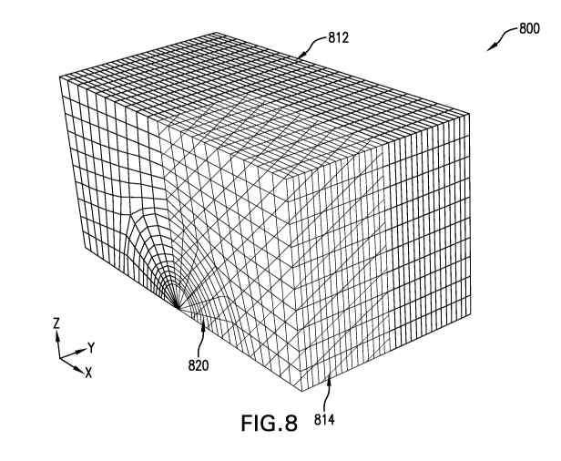
FIG. 8 is a diagram of an illustrative 3D sub-model 800 of a selected portion
of the
subsurface formation corresponding to portion 710 of the 3D global model 700
of FIG. 7.
The 3D sub-model 800 may be generated using various sub-modeling techniques
that
accommodate for the discrepancy in scale between the two models. Such
techniques also
may be used to derive appropriate boundary conditions for the smaller scale 3D
sub-model
is 800 from the larger scale 3D global model 700. Like the 3D global model
700, the 3D sub-
model 800 may be a 3D FEM model. However, the mesh density of the 3D sub-model
800
may be further increased to improve the accuracy of displacement calculations
related to
the fracture distributions within the selected portion of the formation. While
not shown in
FIG. 8, a second or refined version of the 3D sub-model 800 may be generated
using
modeling techniques similar to those used to generate 3D sub-model 800 from
the 3D sub-
model 700 of FIG. 7. Such a refined 3D sub-model may be, for example, a
version of 3D
sub-model 800 that is generated with a higher mesh density to further improve
accuracy but
at a smaller scale to maintain computational efficiency, e.g., within
acceptable limits. For
example, such a smaller-scale refined 3D sub-model may correspond to a portion
of the 3D
sub-model 800 that has a similar shape with smaller dimensions in proportion
to the 3D
sub-model 800.
As shown in FIG. 8, the 3D sub-model 800 includes areas 812 and 814
corresponding to areas 712 and 714, respectively, of the 3D global model 700
of FIG. 7, as
described above. Area 814 of the formation may represent a high fracture
density area of
the selected portion of the formation corresponding to a fraction (e.g., one
quarter) of the
model's geometry. The casing and cement ring around the casing are represented
in an area
820 of the 3D sub-model 800.
25 of 48
CA 03000641 2018-03-29
WO 2017/078674 PCT/US2015/058648
FIG. 9 is a diagram showing a cross-sectional view 900 of the 3D sub-model 800
including the casing and cement area 820 of FIG. 8. As shown in FIG. 9, the
cross-
sectional view 900 includes low and high fracture density formation areas 912
and 914
corresponding to areas 812 and 814 of the 3D sub-model 800, respectively.
Also, as shown
in FIG. 9, a cement ring 920 includes has been divided into different segments
based on the
quality of the cementing material used in each segment. For example, segments
922 and
926 may represent parts of the cementing ring 920 in which relatively high-
quality
cementing material was used. However, a segment 924 of the cementing ring 920
may
represent a relatively weaker part of the cementing ring 920 in which low-
quality
io cementing material was used or poor quality cementing work was
performed.
To simulate an unevenness of the cement sheath filling caused by poor quality
cementing material or well cementation work, the cementing material parameters
(e.g.,
Young's modulus) for each of segments 922 and 926 in the 3D sub-model may be
assigned
a default value representing cementing material of good or acceptable quality
while the
is cementing material parameters for segment 924 may be assigned a
relatively lower value.
The cementing material parameters in segment 924 may also be assigned a
relatively lower
value due to imperfections (e.g., air bubbles) within the cementing material.
For example,
such poor quality cementing material can be assigned a value of zero or one
that is 10% of
the default value assigned to the acceptable or good-quality cementing
material of segments
20 922 and 926 of the cementing ring 920. Thus, if the value of Young's
modulus assigned to
each of segments 922 and 926 in this example is 27.2 GPa, the value assigned
to segment
924 may be 2.72 GPa.
It should be appreciated that the disclosed embodiments are not intended to be
limited to only two types of quality and that parameter values representing a
range of
25 quality, e.g., between very good and very poor, may also be used as
desired for a particular
implementation. The size of each segment or percentage of the cementing ring
920
covered by each segment may vary based on, for example, a measured or
predetermined
quality index associated with the cementing material within each segment.
Once the material parameter values have been assigned to the 3D global model
700
30 of FIG. 7 and the 3D sub-model 800 of FIG. 8 as described above, one or
more numerical
damage models can be applied to the 3D global model 700 and the 3D sub-model
800 to
simulate the hydraulic fracturing effects of one or more stages of the
multistage hydraulic
26 of 48
CA 03000641 2018-03-29
WO 2017/078674 PCT/US2015/058648
fracturing treatment on the subsurface formation and the casing along the
planned wellbore
trajectory therein. As described above, the results of the simulation using
the 3D global
model 700 are used as boundary conditions for the simulation using the 3D sub-
model 800.
The results of the simulation using the 3D sub-model 800 may then be used to
estimate
casing deformation along the wellbore trajectory, as shown in FIGS. 10A-11B.
FIGS. 10A and 10B are 3D meshes illustrating estimated values of casing
deformation with relatively high quality cementing material along the
horizontal wellbore.
In FIG. 10A, a 3D mesh 1000A illustrates casing deformation in a lateral
direction relative
to the horizontal wellbore trajectory. In FIG. 10B, a 3D mesh 1000B
illustrates casing
io deformation in a vertical direction relative to the horizontal wellbore
trajectory. The values
shown alongside 3D mesh 1000A in FIG. 10A may represent, for example, the
maximum
amount of lateral displacement estimated for the casing along the wellbore
trajectory during
one or more stages of the simulated hydraulic fracturing injection treatment
in this
example. Similarly, the values shown alongside 3D mesh 1000B in FIG. 10B may
is represent the maximum amount of vertical displacement estimated for the
casing along the
wellbore trajectory during the simulated hydraulic fracturing injection
treatment stage(s).
FIG. 11A and 11B are 3D meshes illustrating estimated values of casing
deformation with relatively low quality cementing material along the
horizontal wellbore.
In FIG. 11A, a 3D mesh 1100A illustrates casing deformation in a lateral
direction relative
20 to a horizontal wellbore trajectory. In FIG. 11B, a 3D mesh 1100B
illustrates casing
deformation in a vertical direction relative to the horizontal wellbore
trajectory. Similar to
FIGS. 10A and 10B, the values listed alongside 3D mesh 1100A and 3D mesh 1100B
may
represent the maximum amount of lateral and vertical displacement,
respectively, estimated
for the casing along the wellbore trajectory during one or more stages of the
simulated
25 hydraulic fracturing injection treatment as described above. In some
implementations, a
predetermined maximum threshold displacement value may be used to determine
whether
or not any of the maximum lateral displacement and/or vertical displacement
values
estimated for the casing represent a significant or an unacceptable level of
casing
deformation.
30 A comparison between the lateral displacement values ("Ul") shown
alongside 3D
meshes 1000A and 1100A in FIGS. 10A and 11A, respectively, reveal that the
estimated
casing deformation expected to occur in the lateral direction is similar for
both high-quality
27 of 48
CA 03000641 2018-03-29
WO 2017/078674 PCT/US2015/058648
and low-quality cementing materials. However, a comparison of the vertical
displacement
values ("U3") shown alongside 3D meshes 1000B and 1100B in FIGS. 10B and 11B,
respectively, reveal that the estimated vertical casing deformation expected
to occur with
low quality cementing material is significantly larger than with high quality
cementing
material. This comparison therefore shows that the quality of the cementing
material may
be a significant factor that can intensify the amount of vertical casing
deformation during
hydraulic fracturing injection treatments along the wellbore.
Table 1 below further shows maximum values of the von Mises equivalent stress
estimated for the casing under different hydraulic fracturing injection
pressures, e.g., based
io on the simulation using the 3D sub-model 800, as described above with
respect to FIGS. 8
and 9:
Maximum value of
Distribution of Asymmetric
Injection casing deformation
Properties
Pressure /mm
/MPaCement ring
lateral vertical Fractures
quality
90 15.6 7.18 Asymmetric poor
90 14.9 0.2 Asymmetric
80 9.5 0.83 Asymmetric poor
80 5.7 0.34 Asymmetric
Table 1
Each maximum value of casing deformation listed in each row of Table 1 above
represents the maximum value of either lateral or vertical displacement
estimated for the
casing under a particular hydraulic fracturing injection pressure. It may be
assumed that 90
MPa is the peak value of hydraulic fracturing injection pressure in this
example. The
following observations may be made based on the values shown in Table 1: (1)
when the
value of injection pressure is equivalent to the 90 MPa peak value, the
quality of the
cementing material associated with the cement ring may have a large impact on
the amount
of vertical displacement that can occur, but only a small impact on the amount
of lateral
displacement; (2) when the injection pressure is decreased to a value of 80
MPa, the
28 of 48
CA 03000641 2018-03-29
WO 2017/078674 PCT/US2015/058648
amount of displacement in both lateral and vertical directions is
significantly lower than
when the injection pressure is at its peak value; and (3) 80 MPa may be a safe
value for the
maximum injection pressure that can be used without causing significant casing
deformation and that can be used as the maximum injection pressure threshold
to maintain
casing integrity during the hydraulic fracturing injection treatment in this
example.
As noted previously, the major factors contributing to the occurrence of
significant
casing deformation during hydraulic fracturing injection stimulation
operations include:
(1) high values of injection pressure; (2) an asymmetric distribution natural
and/or induced
fractures within the surrounding formation; and (3) the quality of the cement
ring around
io the casing, including the quality of the cementing material and whether
or not that material
was uniformly distributed around the casing when the ring was formed. While
hydraulic
fracturing injection pressure may be the leading factor, Table 1 shows that
cementing
quality may be the primary factor that impacts the amount or intensity of any
casing
deformation that occurs as a result of high hydraulic fracturing injection
pressures.
As described above, the casing deformation values estimated based on the
simulation in this example may be used to determine or adjust one or more
hydraulic
fracturing treatment design parameters including, but not limited to, a
maximum fluid
injection pressure for each stage of the multistage hydraulic fracturing
treatment and a
quality of the cementing material used for the casing along each treatment
stage. Also, as
described above, the disclosed modeling and casing deformation estimation
techniques
enable the interaction between the formation and the casing to be simulated in
a fully
coupled way. Therefore, advantages of the disclosed techniques include, but
are not
limited to, providing a computationally efficient way to estimate casing
deformation that
allows system performance to be improved without sacrificing numerical
accuracy.
FIG. 12 is a block diagram of an exemplary computer system 1200 in which
embodiments of the present disclosure may be implemented. For example, the
steps of
process 500 of FIG. 5, as described above, may be implemented using system
1200.
System 1200 can be a computer, phone, PDA, or any other type of electronic
device. Such
an electronic device includes various types of computer readable media and
interfaces for
various other types of computer readable media. As shown in FIG. 12, system
1200
includes a permanent storage device 1202, a system memory 1204, an output
device
29 of 48
CA 03000641 2018-03-29
WO 2017/078674 PCT/US2015/058648
interface 1206, a system communications bus 1208, a read-only memory (ROM)
1210,
processing unit(s) 1212, an input device interface 1214, and a network
interface 1216.
Bus 1208 collectively represents all system, peripheral, and chipset buses
that
communicatively connect the numerous internal devices of system 1200. For
instance, bus
1208 communicatively connects processing unit(s) 1212 with ROM 1210, system
memory
1204, and permanent storage device 1202.
From these various memory units, processing unit(s) 1212 retrieves
instructions to
execute and data to process in order to execute the processes of the subject
disclosure. The
processing unit(s) can be a single processor or a multi-core processor in
different
i o implementations.
ROM 1210 stores static data and instructions that are needed by processing
unit(s)
1212 and other modules of system 1200. Permanent storage device 1202, on the
other
hand, is a read-and-write memory device. This device is a non-volatile memory
unit that
stores instructions and data even when system 1200 is off Some implementations
of the
is subject disclosure use a mass-storage device (such as a magnetic or
optical disk and its
corresponding disk drive) as permanent storage device 1202.
Other implementations use a removable storage device (such as a floppy disk,
flash
drive, and its corresponding disk drive) as permanent storage device 1202.
Like permanent
storage device 1202, system memory 1204 is a read-and-write memory device.
However,
20 unlike storage device 1202, system memory 1204 is a volatile read-and-
write memory, such
a random access memory. System memory 1204 stores some of the instructions and
data
that the processor needs at runtime. In some implementations, the processes of
the subject
disclosure are stored in system memory 1204, permanent storage device 1202,
and/or ROM
1210. For example, the various memory units include instructions for computer
aided pipe
25 string design based on existing string designs in accordance with some
implementations.
From these various memory units, processing unit(s) 1212 retrieves
instructions to execute
and data to process in order to execute the processes of some implementations.
Bus 1208 also connects to input and output device interfaces 1214 and 1206.
Input
device interface 1214 enables the user to communicate information and select
commands to
30 the system 1200. Input devices used with input device interface 1214
include, for example,
alphanumeric, QWERTY, or T9 keyboards, microphones, and pointing devices (also
called
"cursor control devices"). Output device interfaces 1206 enables, for example,
the display
30 of 48
CA 03000641 2018-03-29
WO 2017/078674 PCT/US2015/058648
of images generated by the system 1200. Output devices used with output device
interface
1206 include, for example, printers and display devices, such as cathode ray
tubes (CRT) or
liquid crystal displays (LCD). Some implementations include devices such as a
touchscreen that functions as both input and output devices. It should be
appreciated that
embodiments of the present disclosure may be implemented using a computer
including
any of various types of input and output devices for enabling interaction with
a user. Such
interaction may include feedback to or from the user in different forms of
sensory feedback
including, but not limited to, visual feedback, auditory feedback, or tactile
feedback.
Further, input from the user can be received in any form including, but not
limited to,
io acoustic, speech, or tactile input. Additionally, interaction with the
user may include
transmitting and receiving different types of information, e.g., in the form
of documents, to
and from the user via the above-described interfaces.
Also, as shown in FIG. 12, bus 1208 also couples system 1200 to a public or
private
network (not shown) or combination of networks through a network interface
1216. Such a
is network may include, for example, a local area network ("LAN"), such as
an Intranet, or a
wide area network ("WAN"), such as the Internet. Any or all components of
system 1200
can be used in conjunction with the subject disclosure.
These functions described above can be implemented in digital electronic
circuitry,
in computer software, firmware or hardware. The techniques can be implemented
using
20 one or more computer program products. Programmable processors and
computers can be
included in or packaged as mobile devices. The processes and logic flows can
be
performed by one or more programmable processors and by one or more
programmable
logic circuitry. General and special purpose computing devices and storage
devices can be
interconnected through communication networks.
25 Some implementations include electronic components, such as
microprocessors,
storage and memory that store computer program instructions in a machine-
readable or
computer-readable medium (alternatively referred to as computer-readable
storage media,
machine-readable media, or machine-readable storage media). Some examples of
such
computer-readable media include RAM, ROM, read-only compact discs (CD-ROM),
30 recordable compact discs (CD-R), rewritable compact discs (CD-RW), read-
only digital
versatile discs (e.g., DVD-ROM, dual-layer DVD-ROM), a variety of
recordable/rewritable
DVDs (e.g., DVD-RAM, DVD-RW, DVD+RW, etc.), flash memory (e.g., SD cards, mini-
31 of 48
CA 03000641 2018-03-29
WO 2017/078674 PCT/US2015/058648
SD cards, micro-SD cards, etc.), magnetic and/or solid state hard drives, read-
only and
recordable Blu-Ray discs, ultra density optical discs, any other optical or
magnetic media,
and floppy disks. The computer-readable media can store a computer program
that is
executable by at least one processing unit and includes sets of instructions
for performing
various operations. Examples of computer programs or computer code include
machine
code, such as is produced by a compiler, and files including higher-level code
that are
executed by a computer, an electronic component, or a microprocessor using an
interpreter.
While the above discussion primarily refers to microprocessor or multi-core
processors that execute software, some implementations are performed by one or
more
io integrated circuits, such as application specific integrated circuits
(ASICs) or field
programmable gate arrays (FPGAs). In some implementations, such integrated
circuits
execute instructions that are stored on the circuit itself. Accordingly, the
steps of process
500 of FIG. 5, as described above, may be implemented using system 1200 or any
computer system having processing circuitry or a computer program product
including
is instructions stored therein, which, when executed by at least one
processor, causes the
processor to perform functions relating to these methods.
As used in this specification and any claims of this application, the terms
"computer", "server", "processor", and "memory" all refer to electronic or
other
technological devices. These terms exclude people or groups of people. As used
herein,
20 the terms "computer readable medium" and "computer readable media" refer
generally to
tangible, physical, and non-transitory electronic storage mediums that store
information in
a form that is readable by a computer.
Embodiments of the subject matter described in this specification can be
implemented in a computing system that includes a back end component, e.g., as
a data
25 server, or that includes a middleware component, e.g., an application
server, or that
includes a front end component, e.g., a client computer having a graphical
user interface or
a Web browser through which a user can interact with an implementation of the
subject
matter described in this specification, or any combination of one or more such
back end,
middleware, or front end components. The components of the system can be
30 interconnected by any form or medium of digital data communication, e.g., a
communication network. Examples of communication networks include a local area
32 of 48
CA 03000641 2018-03-29
WO 2017/078674 PCT/US2015/058648
network ("LAN") and a wide area network ("WAN"), an inter-network (e.g., the
Internet),
and peer-to-peer networks (e.g., ad hoc peer-to-peer networks).
The computing system can include clients and servers. A client and server are
generally remote from each other and typically interact through a
communication network.
The relationship of client and server arises by virtue of computer programs
running on the
respective computers and having a client-server relationship to each other. In
some
embodiments, a server transmits data (e.g., a web page) to a client device
(e.g., for purposes
of displaying data to and receiving user input from a user interacting with
the client
device). Data generated at the client device (e.g., a result of the user
interaction) can be
io received from the client device at the server.
It is understood that any specific order or hierarchy of steps in the
processes
disclosed is an illustration of exemplary approaches. Based upon design
preferences, it is
understood that the specific order or hierarchy of steps in the processes may
be rearranged,
or that all illustrated steps be performed. Some of the steps may be performed
is
simultaneously. For example, in certain circumstances, multitasking and
parallel
processing may be advantageous. Moreover, the separation of various system
components
in the embodiments described above should not be understood as requiring such
separation
in all embodiments, and it should be understood that the described program
components
and systems can generally be integrated together in a single software product
or packaged
20 into multiple software products.
Furthermore, the exemplary methodologies described herein may be implemented
by a system including processing circuitry or a computer program product
including
instructions which, when executed by at least one processor, causes the
processor to
perform any of the methodology described herein.
25 As
described above, embodiments of the present disclosure are particularly useful
for modeling casing deformation for hydraulic fracturing design. Accordingly,
advantages
of the present disclosure include using fully coupled modeling techniques to
provide a
computationally efficient workflow for estimating casing deformation that
allows system
performance to be improved without sacrificing numerical accuracy.
30 In
one embodiment of the present disclosure, a computer-implemented method of
modeling casing deformation for hydraulic fracturing design includes:
generating a three-
dimensional (3D) global model of a subsurface formation targeted for a
multistage
33 of 48
CA 03000641 2018-03-29
WO 2017/078674 PCT/US2015/058648
hydraulic fracturing treatment to be performed along a planned trajectory of a
wellbore
within the subsurface formation; calculating values of material parameters for
different
points of the subsurface formation represented by the 3D global model, based
on a
geomechanical analysis of well log data obtained for the subsurface formation;
assigning
the calculated values to corresponding points of the 3D global model;
generating a 3D sub-
model of a selected portion of the subsurface formation including a casing to
be placed
along the planned trajectory of the wellbore within the subsurface formation,
based at least
partly on the values assigned to the 3D global model; applying one or more
numerical
damage models to the 3D global model to simulate hydraulic fracturing effects
of one or
io more stages of the multistage hydraulic fracturing treatment on the
subsurface formation;
applying the one or more numerical damage models to the 3D sub-model to
simulate the
hydraulic fracturing effects of the one or more stages of the multistage
hydraulic fracturing
treatment on the casing along the planned trajectory of the wellbore within
the subsurface
formation, based on the simulation using the 3D global model; and estimating
at least one
is value of casing deformation along the planned trajectory of the
wellbore, based on the
simulation using the 3D sub-model. Further, a computer-readable storage medium
with
instructions stored therein has been described, where the instructions when
executed by a
computer cause the computer to perform a plurality of functions, including
functions to:
generate a three-dimensional (3D) global model of a subsurface formation
targeted for a
20 multistage hydraulic fracturing treatment to be performed along a
planned trajectory of a
wellbore within the subsurface formation; calculate values of material
parameters for
different points of the subsurface formation represented by the 3D global
model, based on a
geomechanical analysis of well log data obtained for the subsurface formation;
assign the
calculated values to corresponding points of the 3D global model; generate a
3D sub-model
25 of a selected portion of the subsurface formation including a casing to
be placed along the
planned trajectory of the wellbore within the subsurface formation, based at
least partly on
the values assigned to the 3D global model; apply one or more numerical damage
models
to the 3D global model to simulate hydraulic fracturing effects of one or more
stages of the
multistage hydraulic fracturing treatment on the subsurface formation; apply
the one or
30 more numerical damage models to the 3D sub-model to simulate the
hydraulic fracturing
effects of the one or more stages of the multistage hydraulic fracturing
treatment on the
casing along the planned trajectory of the wellbore within the subsurface
formation, based
34 of 48
CA 03000641 2018-03-29
WO 2017/078674 PCT/US2015/058648
on the simulation using the 3D global model; and estimate at least one value
of casing
deformation along the planned trajectory of the wellbore, based on the
simulation using the
3D sub-model.
For the foregoing embodiments, the value of casing deformation may be
estimated
for one or more sections of the wellbore that correspond to the one or more
stages of the
multistage hydraulic fracturing treatment and/or each of a plurality of fluid
injection
pressures associated with the one or more stages of the multistage hydraulic
fracturing
treatment. The wellbore may be a horizontal wellbore, and the estimated value
of casing
deformation may be a maximum value of at least one of a lateral displacement
or a vertical
io displacement estimated for the casing associated with each of the one or
more sections
along the planned trajectory of the horizontal wellbore within the subsurface
formation.
The one or more numerical damage models may be applied to each of the 3D
global model
and the 3D sub-model to simulate an asymmetrical distribution of fractures
generated by
the one or more stages of the multistage hydraulic fracturing treatment within
the
is subsurface formation. The material parameters may include an elasticity
modulus, and the
asymmetrical distribution of fractures may be simulated by varying values of
the elasticity
modulus assigned to the different points of the subsurface formation
corresponding to the
selected portion modeled by the 3D sub-model. Such different points may
include: a first
set of points corresponding to a first area of the selected portion on one
side of the planned
20 trajectory of the wellbore having a relatively low density of natural
fractures; a second set
of points corresponding to a second area of the selected portion on another
side of the
planned trajectory of the wellbore having a relatively high density of natural
fractures; and
a third set of points corresponding to a location of a cement ring surrounding
the casing.
The values of the elasticity modulus assigned to points of the 3D sub-model
corresponding
25 to the second set of points may be relatively lower than those assigned
to points of the 3D
sub-model corresponding to the first set of points. The values of the
elasticity modulus
assigned to points of the 3D sub-model corresponding to the third set of
points may be
based on a quality of cementing material associated with different segments of
the cement
ring. The one or more numerical damage models may be applied to the 3D sub-
model to
30 simulate a stiffness degradation of the cementing material associated
with one or more of
the different segments of the cement ring based on the values of the
elasticity modulus
assigned to corresponding points of the 3D sub-model.
35 of 48
CA 03000641 2018-03-29
WO 2017/078674 PCT/US2015/058648
Further, the foregoing embodiments may include any one of the following
functions, operations or elements, alone or in combination with each other:
generating a
refined version of the 3D sub-model based on the simulated stiffness
degradation of the
cementing material; applying the one or more numerical damage models to the
refined
version of the 3D sub-model to simulate the stiffness degradation of the
cementing
material; and estimating at least one refined value of casing deformation
along the planned
trajectory of the wellbore, based on the simulation using the refined version
of the 3D sub-
model. Further, such embodiments may include determining one or more design
parameters for each stage of the multistage hydraulic fracturing treatment to
be performed
io along the planned trajectory of the wellbore, based on the estimated
value of casing
deformation. The one or more design parameters may include one or more of a
maximum
fluid injection pressure for each stage of the multistage hydraulic fracturing
treatment and a
quality of cementing material associated with the casing within one or more
sections of the
wellbore along the planned trajectory.
Likewise, a system has been described, which includes at least one processor
and a
memory coupled to the processor that has instructions stored therein, which
when executed
by the processor, cause the processor to perform functions, including
functions to: generate
a three-dimensional (3D) global model of a subsurface formation targeted for a
multistage
hydraulic fracturing treatment to be performed along a planned trajectory of a
wellbore
within the subsurface formation; calculate values of material parameters for
different points
of the subsurface formation represented by the 3D global model, based on a
geomechanical
analysis of well log data obtained for the subsurface formation; assign the
calculated values
to corresponding points of the 3D global model; generate a 3D sub-model of a
selected
portion of the subsurface formation including a casing to be placed along the
planned
trajectory of the wellbore within the subsurface formation, based at least
partly on the
values assigned to the 3D global model; apply one or more numerical damage
models to
the 3D global model to simulate hydraulic fracturing effects of one or more
stages of the
multistage hydraulic fracturing treatment on the subsurface formation; apply
the one or
more numerical damage models to the 3D sub-model to simulate the hydraulic
fracturing
effects of the one or more stages of the multistage hydraulic fracturing
treatment on the
casing along the planned trajectory of the wellbore within the subsurface
formation, based
on the simulation using the 3D global model; and estimate at least one value
of casing
36 of 48
CA 03000641 2018-03-29
WO 2017/078674 PCT/US2015/058648
deformation along the planned trajectory of the wellbore, based on the
simulation using the
3D sub-model.
In one or more embodiments of the foregoing system, the value of casing
deformation may be estimated for one or more sections of the wellbore that
correspond to
the one or more stages of the multistage hydraulic fracturing treatment and/or
each of a
plurality of fluid injection pressures associated with the one or more stages
of the
multistage hydraulic fracturing treatment. The wellbore may be a horizontal
wellbore, and
the estimated value of casing deformation may be a maximum value of at least
one of a
lateral displacement or a vertical displacement estimated for the casing
associated with
io each of the one or more sections along the planned trajectory of the
horizontal wellbore
within the subsurface formation. The one or more numerical damage models may
be
applied to each of the 3D global model and the 3D sub-model to simulate an
asymmetrical
distribution of fractures generated by the one or more stages of the
multistage hydraulic
fracturing treatment within the subsurface formation. The material parameters
may include
is an elasticity modulus, and the asymmetrical distribution of fractures
may be simulated by
varying values of the elasticity modulus assigned to the different points of
the subsurface
formation corresponding to the selected portion modeled by the 3D sub-model.
Such
different points may include: a first set of points corresponding to a first
area of the
selected portion on one side of the planned trajectory of the wellbore having
a relatively
20 low density of natural fractures; a second set of points corresponding
to a second area of
the selected portion on another side of the planned trajectory of the wellbore
having a
relatively high density of natural fractures; and a third set of points
corresponding to a
location of a cement ring surrounding the casing. The values of the elasticity
modulus
assigned to points of the 3D sub-model corresponding to the second set of
points may be
25 relatively lower than those assigned to points of the 3D sub-model
corresponding to the
first set of points. The values of the elasticity modulus assigned to points
of the 3D sub-
model corresponding to the third set of points may be based on a quality of
cementing
material associated with different segments of the cement ring. The one or
more numerical
damage models may be applied to the 3D sub-model to simulate a stiffness
degradation of
30 the cementing material associated with one or more of the different
segments of the cement
ring based on the values of the elasticity modulus assigned to corresponding
points of the
3D sub-model.
37 of 48
CA 03000641 2018-03-29
WO 2017/078674 PCT/US2015/058648
Further, the functions performed by the processor may include functions to:
generate a refined version of the 3D sub-model based on the simulated
stiffness
degradation of the cementing material; apply the one or more numerical damage
models to
the refined version of the 3D sub-model to simulate the stiffness degradation
of the
cementing material; and estimate at least one refined value of casing
deformation along the
planned trajectory of the wellbore, based on the simulation using the refined
version of the
3D sub-model. In some implementations, the functions performed by the
processor may
further include functions to determine one or more design parameters for each
stage of the
multistage hydraulic fracturing treatment to be performed along the planned
trajectory of
io the wellbore, based on the estimated value of casing deformation. The
one or more design
parameters may include one or more of a maximum fluid injection pressure for
each stage
of the multistage hydraulic fracturing treatment and a quality of cementing
material
associated with the casing within one or more sections of the wellbore along
the planned
traj ectory.
While specific details about the above embodiments have been described, the
above
hardware and software descriptions are intended merely as example embodiments
and are
not intended to limit the structure or implementation of the disclosed
embodiments. For
instance, although many other internal components of the system 1200 are not
shown, those
of ordinary skill in the art will appreciate that such components and their
interconnection
are well known.
In addition, certain aspects of the disclosed embodiments, as outlined above,
may
be embodied in software that is executed using one or more processing
units/components.
Program aspects of the technology may be thought of as "products" or "articles
of
manufacture" typically in the form of executable code and/or associated data
that is carried
on or embodied in a type of machine readable medium. Tangible non-transitory
"storage"
type media include any or all of the memory or other storage for the
computers, processors
or the like, or associated modules thereof, such as various semiconductor
memories, tape
drives, disk drives, optical or magnetic disks, and the like, which may
provide storage at
any time for the software programming.
Additionally, the flowchart and block diagrams in the figures illustrate the
architecture, functionality, and operation of possible implementations of
systems, methods
and computer program products according to various embodiments of the present
38 of 48
CA 03000641 2018-03-29
WO 2017/078674 PCT/US2015/058648
disclosure. It should also be noted that, in some alternative implementations,
the functions
noted in the block may occur out of the order noted in the figures. For
example, two blocks
shown in succession may, in fact, be executed substantially concurrently, or
the blocks may
sometimes be executed in the reverse order, depending upon the functionality
involved. It
will also be noted that each block of the block diagrams and/or flowchart
illustration, and
combinations of blocks in the block diagrams and/or flowchart illustration,
can be
implemented by special purpose hardware-based systems that perform the
specified
functions or acts, or combinations of special purpose hardware and computer
instructions.
The above specific example embodiments are not intended to limit the scope of
the
io claims. The example embodiments may be modified by including, excluding,
or
combining one or more features or functions described in the disclosure.
As used herein, the singular forms "a", "an" and "the" are intended to include
the
plural forms as well, unless the context clearly indicates otherwise. It will
be further
understood that the terms "comprise" and/or "comprising," when used in this
specification
is and/or the claims, specify the presence of stated features, integers,
steps, operations,
elements, and/or components, but do not preclude the presence or addition of
one or more
other features, integers, steps, operations, elements, components, and/or
groups thereof
The corresponding structures, materials, acts, and equivalents of all means or
step plus
function elements in the claims below are intended to include any structure,
material, or act
20 for performing the function in combination with other claimed elements
as specifically
claimed. The description of the present disclosure has been presented for
purposes of
illustration and description, but is not intended to be exhaustive or limited
to the
embodiments in the form disclosed. Many modifications and variations will be
apparent to
those of ordinary skill in the art without departing from the scope and spirit
of the
25 disclosure. The illustrative embodiments described herein are provided
to explain the
principles of the disclosure and the practical application thereof, and to
enable others of
ordinary skill in the art to understand that the disclosed embodiments may be
modified as
desired for a particular implementation or use. The scope of the claims is
intended to
broadly cover the disclosed embodiments and any such modification.
39 of 48