Note: Descriptions are shown in the official language in which they were submitted.
, .
'...
B&P-054
EXTERNAL FUNCTIONAL MEANS, BLOOD TREATMENT APPARATUS FOR
ACCOMMODATING SUCH EXTERNAL FUNCTIONAL MEANS, AND METHOD
[0001] The present invention relates to an external functional
means. It further
relates to a blood treatment apparatus, as well as methods.
[0002] Cleaning of the equipment utilized in blood treatments may
be technically
complex. In order to guarantee sufficient hygiene at acceptable work
expenditure as well
as for other reasons, external functional means such as blood cassettes are
employed.
[0003] Such a blood cassette may be adapted to fulfill as many
functions as
possible for the preparation and performance of blood treatment methods.
[0004] It is an object of the present invention to provide another
external functional
means, in particular a blood treatment cassette. Moreover it is intended to
propose a blood
treatment apparatus comprising a like external functional means or being
adapted for
driving and operating it, and corresponding methods for its use.
[0005] The object of the invention is achieved through an external
functional means
having the features described herein.
[0006] The external functional means comprises at least one housing
body, at least
one chamber integrated into the housing body for receiving medical fluids, at
least one
passage integrated into the housing body for receiving and/or conducting a
medical fluid,
and at least one valve means completely or partly integrated into the housing
body for
controlling or regulating a fluid flowing through the external functional
means.
[0007] The expression "housing body" as presently used designates a
three
dimensional body and formed of a material that is suitable for use in a
medical treatment
1
CA 3000690 2018-04-09
B&P-054
method such as, for example, a blood treatment method, for example a plastic
material.
The housing body may, for example, be manufactured with the aid of a casting
or injection
molding method.
[0008] The
expression "chamber" as presently used designates a volume suited for
receiving at least one medical fluid. The volume may be a closed space or may
be defined
by such a closed space. It may, however, also be an open space or be partly
surrounded
by such an open space, and only become a closed space - or a space closed with
the
exception of supply and discharge conduits for the fluid - as a result of the
presence of
some other body, namely, a body other than the housing body.
[0009] Chambers may
be adapted and intended for receiving valves and/or
sensors, or the like.
[0010] The
expression "passage" or "conduit" as presently used designates a
means that is suited for receiving and/or conducting medical fluids such as,
for example,
blood, heparin or other medicaments, saline solution, substituate, and the
like.
[0011] Passages
or conduits may be configured as closed and/or semi-open
structures in portions thereof. They may, for example, be adapted for being
closed on at
least one open side by means of cover means and thus be configured to be
sealable
against, for instance, components of a blood treatment apparatus and/or
against the
atmosphere.
[0012] The
expression "valve means" as presently used designates a means suited
for controlling or regulating which may control the admission or passageway of
fluids
through passages or conduits and/or chambers of the external functional means.
Valve
means may be driven by means of control or regulation means provided for this
purpose.
2
CA 3000690 2018-04-09
. .
B&P-054
Driving may, for example, take place in an automated manner. Suitable control
or
regulation means may, for example, be provided in or on the blood treatment
apparatus.
[0013] Advantageous embodiments or developments of the external
functional
means of the invention are disclosed herein.
[0014] According to the certain embodiments of the invention, a functional
means
is a means by means of which functions such as conducting fluid by means of
lines,
valves, clot trapping and/or the like can be realized.
[0015] According to the some embodiments of the invention, an
external functional
means is not a permanent part of a treatment apparatus. Rather, an external
functional
io means according to these embodiments is connected with the treatment
apparatus for the
purpose of a treatment from external.
[0016] In a preferred embodiment, the external functional means is
provided on at
least one of its surfaces with a cover means which is part of at least one
integrated valve
means.
[0017] In another preferred embodiment, the cover means is connected by
frictional
and/or by form closure and/or by material connection with the housing body in
at least a
portion thereof. The cover means may, for example, be connected to the housing
body by
means of a peripheral weld or some other type of peripheral connection. Other
non-
peripheral or dot-shaped or local welds or connections (e.g., bonded or
pressed
connections) of the cover means with the housing body may also be provided.
[0018] In certain embodiments according to the invention, the cover
means is - in
certain ranges or areas thereof, respectively ¨ connected with the external
functional
means, in particular with the housing body, along two sides or bilaterally of,
respectively,
3
CA 3000690 2018-04-09
B&P-054
structures (at least one structure) of the external functional means.
According to the
invention, the term "along or at both sides" or "bilaterally" may be
understood as being
present at least on two sides of the respective structure. A bilateral
connection may be
understood as an at least twofold connection in the section, in particular in
the adjacent
section, or in the environment or surrounding area, respectively, of the
structure, in
particular in close proximity.
[0019] Among these structures are i.a. fluid channels, lines or other
elements of the
external functional means. Preferably, those elements are open in a cross-
section
perpendicular to the main extension plane of the cover means and/or are
covered by
means of the cover means against an outside or the atmosphere.
[0020] The bilateral connection can be a weldseam. It can be fluid-
tight in each
case, e.g., such that fluid, in particular, liquid is not exchanged through
the joining area
(the area in which, e.g., the bonding or weldseam has been made). The
bilateral
connection may be provided along single fluid channels, lines or other
elements, e.g., in
selected areas of the external functional means; it can be provided for a
plurality thereof
or for all fluid channels, lines or other elements.
[0021] A bilateral connection may be provided both at the left side
and at the right
side of the respective structure. It can be provided both at the top and at
the bottom with
respect to the structure, or the like.
[0022] A bilateral connection can be one, two or more weldings seams along
the
border or edge, respectively, or periphery or the extensions of at least one
structure or a
section thereof.
[0023] A bilateral connection can be completely or in partly extended
lengthwise.
4
CA 3000690 2018-04-09
B&P-054
[0024] In certain embodiments according to the invention, by means of
the bilateral
connection, the complexity required for pressing the external functional means
can
advantageously be reduced. In some embodiments according to the invention, in
particular the requirements for the precision with which the pressing of the
external
functional means on, e.g., a blood treatment apparatus is effected can
advantageously be
reduced. In certain embodiments according to the invention, due to the
bilateral
connection, a lower pressing pressure can advantageously be sufficient. In
some
embodiments according to the invention, there can advantageously be achieved a
more
reliable functioning of valves acting on channels covered by means of the
bilateral
connection.
[0025] A cover means may in particular be a film.
[0026] The film may preferably be a plastic film. For this purpose and
in a preferred
manner any laser-weldable film appearing appropriate to the skilled person may
be
considered.
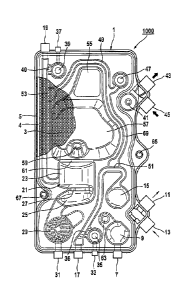
[0027] In another preferred embodiment, the external functional means may
comprise connections for being connected to an extracorporeal circuit in fluid
communication.
[0028] The external functional means may in particular be configured
as a cassette
for a blood treatment.
[0029] In a further preferred manner, the external functional means may be
adapted
to be connected in fluid communication to at least one ¨ preferably two ¨
peristaltic
pump(s) by means of two connectors. Roller pumps may be suitable peristaltic
pumps.
5
CA 3000690 2018-04-09
B&P-054
[0030] The external functional means may comprise at least one ¨
preferably two ¨
pump tube segment(s), or may be configured or provided for receiving such a
pump tube
segment.
[0031] In another preferred embodiment, the external functional means
comprises
at least one valve means which comprises at least one bar and a portion of the
cover
means. The bar is formed on the housing body. Bar and cover means are disposed
for
being operated by means of an actor of a blood treatment apparatus acting on a
bar, in
order to alter a passage of fluid in a valve-like manner.
[0032] Such a "bar" may designate a component that is integrated into
the external
functional means or projects from a surface thereof in any desired direction.
It may be
formed of the same material as the external functional means. A web may, for
example,
be formed during the manufacture of the external functional means by means of
casting
or injection molding methods.
[0033] In another preferred embodiment, the fluid flowing through the
external
functional means during use thereof is a substituate, heparin, or some other
pharmacologically active agent, saline solution (in particular 0.9 % NaCI
solution), blood,
air, as well as combinations thereof.
[0034] The external functional means may in particular be adapted for
being
coupled to a blood treatment apparatus. In a further preferred manner, it may
be
configured and intended for being coupled to the blood treatment apparatus by
means of
a reception means of the blood treatment apparatus. The external functional
means may
in particular be adapted to be coupled to the treatment apparatus at the
surface facing the
cover means.
6
CA 3000690 2018-04-09
B&P-054
[0035] In another preferred embodiment, the external functional means
may be
adapted to be coupled to the blood treatment apparatus at an angle of rearward
inclination
of preferably between 5 degrees and 11 degrees, in particular at an
inclination angle of
substantially or precisely 8 degrees, relative to a vertical. The external
functional means
is preferably inclined to the rear in an upper region thereof (in the
condition of use).
[0036] In another preferred embodiment, the external functional means
comprises
at least one substituate addition site including a touch-protection element
and/or a drip-
protection element. Other portions, in particular every other portion, of the
external
functional means may also comprise a touch-protection element and/or a drip-
protection
element.
[0037] A closure function of the ports (one, some, or all ports) of
the external
functional means may also be realized by means of septa or check valves.
[0038] The drip-protection element may be realized, for example, by an
integrated
closure sleeve.
[0039] The drip-protection element may preferably serve to prevent
substituate or
blood or a mixture of substituate and blood from dripping or trickling out
from the reception
means of the blood treatment apparatus during disassembly of the external
functional
means. In this way, hygienic handling of the used and impure external
functional means
may further be ensured outside of the treatment apparatus.
[0040] The external functional means in accordance with the present
invention may
be suited for use in a blood treatment method employing a double-needle access
or a
single-needle access.
7
CA 3000690 2018-04-09
. ,
B&P-054
[0041] The patient's blood is preferably already being conducted
through the
dialyzer during the phase of withdrawal from the patient, dialyzed in the
process, stored
in the single-needle chamber (preferably immediately) after its passage
through the
dialyzer, and from there returned to the patient in the returning phase. In
this case, the
blood is dialyzed in the "fresh" condition in which it leaves the patient.
Thus, the method
performed for a blood treatment by means of the cassette in accordance with
the invention
may advantageously differ from those conventional methods in which blood is
taken from
the patient, stored in a separate single-needle chamber, subsequently
dialyzed, and
returned to the patient via a venous air separator.
[0042] The external functional means may preferably comprise at least one
single-
needle chamber in which a blood surge redirection element is disposed.
[0043] A like "blood surge redirection element" or blood surge
element may be
suited and intended for achieving a flow deceleration, for generating a
turbulence and/or
redirecting the blood flowing into the single-needle chamber, or for
cancelling the impulse
of the blood surge. A like blood surge redirection element may in particular
be configured
in a rheologically optimized manner. It may, for example, be configured in the
shape of an
ellipsoidal or round column which is connected to a wall of the single-needle
chamber on
at least one portion of its circumference.
[0044] Without a blood surge redirection element, a blood surge
flowing in through
the phantom valve might in a given case cause gushing. This might lead to
hunting
movements or sloshing movements, respectively, of the liquid level and/or to
formation of
foam. By means of the blood surge element the total blood surge is divided
into two
8
CA 3000690 2018-04-09
B&P-054
smaller blood surges, whereby the impulse of the total blood surge may be
cancelled, and
gushing, sloshing movements and/or formation of foam may advantageously be
avoided.
[0045] As a blood surge redirection element, it is preferably possible
to use a blood
surge redirection element as disclosed by the applicant of the present
invention in the
patent application DE102009024466A1 having the title "Aufnahmeeinrichtung zum
Aufnehmen von medizinischen Fluiden sowie exteme Funktionseinrichtung und
medizinische Behandlungsvorrichtung" [Reception means for receiving medical
fluids, as
well as external functional means and medical treatment apparatus] as filed
with the
German Patent and Trademark Office on June 10, 2009.
[0046] The external functional means of the present invention may
preferably
comprise at least one venous blood chamber.
[0047] The single-needle chamber may preferably be arranged above the
venous
blood chamber, relative to the orientation of the external functional means
during its use.
[0048] The venous blood chamber may be subdivided into at least one
upper space
and at least one lower space by means of a cross-sectional restriction of the
housing body.
[0049] The upper space and the lower space may be in fluid
communication or
connection with each other.
[0050] The upper space may be configured so as to allow or generate a
tangential
inflow of fluids flowing through the external functional means. The upper
space may
comprise a region for generating a stable rotational flow of the fluids
flowing through the
external functional means.
[0051] The lower space may comprise a region that is substantially or
entirely free
from rotational flow of the fluids flowing through the external functional
means.
9
CA 3000690 2018-04-09
,
B&P-054
[0052] In a preferred manner, walls or wall portions of the upper
space and/or of
the lower space of the venous blood chamber may be adapted to an inclination
of the
external functional means against a vertical of the blood treatment apparatus.
This may
advantageously allow the blood to flow or stream or pass through the venous
blood
chamber in a rheologically optimized manner. Furthermore, air possibly
contained in the
blood can ascend and thus being separated in an appropriate manner.
[0053] The venous blood chamber may be configured, and in
particular have an air
separator effect, as was disclosed by the applicant of the present invention
in the patent
application DE102009024465B4 having the title "Luftabscheider, exteme
io Funktionseinrichtung, Blutkreislauf sowie Behandlungsvorrichtung" [Air
separator,
external functional means, blood circuit, and treatment apparatus] as filed
with the
German Patent and Trademark Office on June 10, 2009.
[0054] In another preferred embodiment of the external functional
means, the
housing body is configured as a hard part.
[0055] The hard part may be a housing body which is substantially formed
integrally
and out of one material. This housing body may be an injection-molded part. It
may have
a minimum stiffness of more than 400 N/mm2, in a preferred manner 1200-1800
N/mm2
(bending modulus of elasticity).
[0056] In another preferred embodiment of the external functional
means as a blood
treatment cassette, it is in a further preferred embodiment possible to
measure the
pressure in the extracorporeal blood circuit upstream of the dialyzer across
the cover
means or film.
CA 3000690 2018-04-09
B&P-054
[0057] The external functional means may preferably be a single-use
article which
is disposed after having been used once.
[0058] The object of the invention is also achieved through the blood
treatment
apparatus as described herein.
[0059] In another preferred embodiment, the blood treatment apparatus is
configured for receiving at least one external functional means in accordance
with the
present invention.
[0060] In another preferred embodiment, the blood treatment apparatus
comprises
at least one control means and/or actors and/or sensors for driving and/or
operating the
external functional means.
[0061] The control means may be configured as a CPU or a part thereof.
[0062] The control means and/or the actors may be suited and intended,
e.g., for
operating or driving, i.e., for example controlling or regulating, a valve
means. They may
be arranged at a position of the blood treatment apparatus opposite to a valve
means of
the external functional means in the coupled state thereof.
[0063] In another preferred embodiment, the blood treatment apparatus
comprises
at least one reception means for receiving at least one external functional
means in
accordance with the present invention. The reception means may comprise a
coupling
surface for coupling the external functional means in accordance with the
present
invention. Such a coupling surface may, for example, be inclined at an angle
against a
vertical relative to the orientation of the blood treatment apparatus during
its use, in
particular to the rear. Such an angle may be between 5 and 11 degrees, in
particular
substantially or precisely 8 degrees.
11
CA 3000690 2018-04-09
=
B&P-054
[0064] The blood treatment apparatus may be suited for performing a
method or a
method step, as will be described in the following and by making reference to
the figures.
[0065] In another embodiment, the blood treatment apparatus
comprises a control
means ¨ e.g., in the form of a CPU - for operating or regulating an external
functional
means in accordance with the present invention and/or for performing a method
or a
method step, as will be described in the following and by making reference to
the figures.
[0066] Furthermore, the blood treatment apparatus may comprise at
least one actor
for operating an external functional means in accordance with the present
invention or a
portion thereof for performing a method or a method step in accordance with
the present
invention.
[0067] The blood treatment apparatus may in particular also
comprise sensors in
form of information providers, wherein the information serves as signals for
the control
unit for operation of an external functional means in accordance with the
present invention
for performing a method or a method step in accordance with the present
invention.
[0068] The blood treatment apparatus may, for example, be a dialyzing
means.
[0069] The blood treatment apparatus may comprise a control means
for measuring
a parameter present in the extracorporeal circuit or in the blood circuit of
the external
functional means of the invention that is configured as a blood treatment
cassette such
as, for example a pressure, a differential pressure, and the like.
[0070] The differential pressure may be measured between the cassette-
integrated
arterial chamber and the cassette-integrated venous chamber. The differential
pressure
may be used as a measure for the blood-side pressure difference of the
dialyzer. The
control means of the blood treatment apparatus may be configured for
calculating the
12
CA 3000690 2018-04-09
B&P-054
difference, in a given case for comparing the pressure difference to reference
values
(which may be deposited, for example, in the control means or in a memory),
and
optionally for outputting control signals.
[0071] Here it is, for example, advantageously possible to recognize
an onset of
clogging of the dialyzer early on or in due time. Countermeasures may be
taken.
[0072] These may include or consist of the addition of anti-coagulants
such as, e.g.,
heparin, e.g., via the cassette-integrated addition sites.
[0073] Furthermore, it is, e.g., possible to increase the pre-
dilution. It is possible to
switch over from post-dilution to pre-dilution.
[0074] The cassette-integrated measurement sites may furthermore
advantageously enable a transmembrane pressure measurement across the dialyzer
membrane.
[0075] To this end, four measurement sites may be provided where
measurements
are performed with the aid of corresponding means, and the measurement results
of which
are evaluated with the aid of suitable means: one at the filter inlet and one
at the filter
outlet, i.e., at the blood side and at the dialysate side, respectively.
[0076] In some embodiments according to the invention, the external
functional
means is ¨ in certain sections thereof ¨ (at least also) in one direction
perpendicular to
the coupling plane (or to a main section thereof) thicker than other sections.
The thicker
sections ¨ of which one or more can be provided - serve for receiving
measurement
devices such as, e.g., optical measurement devices, ultrasonic devices,
temperature
measurement devices, and the like.
13
CA 3000690 2018-04-09
B&P-054
[0077] Sections of the external functional means which are not thicker
but which
primarily extend in the main extension plane of the external functional means,
preferably
in parallel to a main coupling plane of the external functional means and/or
in parallel to
an actuator-sensor-plate of the treatment apparatus, can have the same effect.
Those
sections (one or more) extending the external functional means can likewise be
thicker;
however, according to the invention, this is not necessary.
[0078] The measurement devices can be connectable or connected with
the
treatment apparatus from a side of the door of the treatment apparatus by
means of which
door, in certain embodiments according to the invention, the external
functional means is
io pressed with the treatment apparatus and/or covered for the purpose of
its use.
[0079] The measurement devices can be connectable or connected with
the
treatment apparatus from a side of an actuator-sensor-plate of the treatment
apparatus
by means of which plate, in some embodiments according to the invention, a
functional or
signal connection is established between the external functional means and the
treatment
apparatus.
[0080] The measurement device arranged in such thicker or longer
sections can,
for example, serve for measuring conditions or states, respectively, within
supplying or
discharging fluid channels of the external functional means (in particular
fluid channels
discharging a fluid out of the external functional means or fluid channels
supplying a fluid
to or into the external functional means). They can be arranged in close
proximity to such
fluid channels.
[0081] All or some of the thicker or longer sections are preferably
provided in a
border or rim area of the external functional means. This can advantageously
enable a
14
CA 3000690 2018-04-09
,
B&P-054
simple connection between the measurement device respectively present in one
of the
afore-mentioned sections and the treatment device. Furthermore, such an
arrangement
in a border or rim area can allow for an easy access.
[0082] The external functional means can comprise measuring points,
for coupling
detectors such as, e.g., optical detectors for detecting line or valve
leakage, in the afore-
mentioned thicker or longer sections or at other positions. Such a leakage
could happen,
e.g., in the proximity of the phantom valves, the non-return valves, in the
supplying or
discharging lines (e.g., leading towards the valves or away from the valves),
or the like.
The measuring points and/or the, in particular optical, detectors can be
arranged at
i 0 corresponding positions.
[0083] In some embodiments according to the invention, the external
functional
means can comprise one or more addition sites each comprising at least one
septum. The
septum can be designed for being easily penetrated during addition; however,
it
advantageously provides sealing and thus safety and tightness.
[0084] Preferably, the addition sites are integrated into the external
functional
means or are integral therewith.
[0085] The addition sites can be arranged in an end area or a border
area of the
external functional means. In some embodiments according to the invention,
such an
arrangement can advantageously allow for an easy access to the addition sites.
In certain
embodiments according to the invention, this particularly applies for a case
in which the
external functional means is in contact (e.g., pressed) with a treatment
apparatus both at
its front side and at its back side for the purpose of coupling therewith and
thus both
reaching the front and the back side for an addition by means of the septum is
CA 3000690 2018-04-09
,
B&P-054
cumbersome or difficult. Therefore, in some embodiments, ergonomic advantages
can be
obtained.
[0086] In further preferred embodiments, supplying lines can be
arranged at or in
the external functional means such that the supplying line (completely or
partly) or a
connection site (such as a connection port of the supplying line) to or with
the supplying
line are present in an upper area of the external functional means ¨
preferably with respect
to an intended or conventional, respectively, position or arrangement of the
external
functional means during its intended or conventional, respectively, use (e.g.,
in a state in
which it is pressed with the treatment apparatus).
[0087] The upper area can be a border or rim area. The upper area can be an
area
above a coupling surface or a coupling area.
[0088] The supplying line can be a line for an anticoagulant. It
can be a heparin
line. A respective syringe pump for the anticoagulant, e.g., heparin, can be
arranged
above the external functional means or the coupling plane thereof during use
of the
external functional means.
[0089] Advantages which can be achieved in some embodiments
according to the
invention also comprise ergonomic advantages, furthermore advantages resulting
from a
shorter supplying line, improved accessibility of the connection site, and so
on.
[0090] Supplying lines can in some embodiments be understood as
lines through
which fluids can be supplied to the extracorporeally flowing blood during use
of the
external functional means in a blood treatment or which are provided
therefore.
[0091] The blood treatment apparatus may comprise a control means
for operating
the cassette valves. The control means may preferably switch over between the
cassette-
16
CA 3000690 2018-04-09
B&P-054
integrated pre- and post-dilution in a freely programmable manner. It may
preferably alter
the substituate stream (volume flow). Information providers may in particular
be the
cassette-integrated pressure measurement sites arranged up- and downstream of
the
dialyzer.
[0092] The object of the invention is furthermore achieved through the
methods of
the invention disclosed herein. The methods shall be explained in the
following.
[0093] By way of example, the blood treatment method shall in the
following be
assumed to be a dialyzing method such as a hemodiafiltration. The blood
treatment
apparatus is, for example, a dialyzing means.
[0094] The dialyzing means comprises an extracorporeal circuit having an
arterial
and a venous portion. The dialyzing means further comprises an arterial and a
venous
patient tube clamp.
[0095] During dialysis, a patient is connected to the extracorporeal
circuit via a
patient's access such as, for example, a fistula, a shunt or graft, or a
catheter exemplarily
having the form of a double-needle access or of a single-needle access.
[0096] The extracorporeal circuit may comprise a blood pump for
conveying blood
as well as a substituate pump for conveying substituate, and corresponding
pump tube
segments.
[0097] The blood pump and the substituate pump may be configured as
peristaltic
pumps, for example roller pumps.
[0098] A "conveying direction" or "direction of flow" of the blood
during a dialysis
treatment designates a direction in which the blood to be purified is usually
conveyed. In
particular it may designate a direction running from the patient via an
arterial needle, an
17
CA 3000690 2018-04-09
B&P-054
arterial portion, a dialyzing means (in the figures from bottom to top), a
venous portion,
and may return to the patient via a venous needle.
[0099] A conveyance of fluid (in particular blood and/or substituate)
taking place
against this conveying direction is referred to as a conveyance, or flow, in
the opposite
direction.
[0100] The blood treatment apparatus comprises a dialyzing means
having a
dialyzing liquid inlet and a dialyzing liquid outlet, wherein the dialyzing
liquid may be
conveyed through the dialyzing means in a direction opposite to the blood (in
the figures
from top to bottom).
1() [0101] A substituate may be introduced or adminisered into the
extracorporeal
circuit through a substituate addition site and through a pre-dilution
addition valve and/or
a post-dilution addition valve.
[0102] The expressions "clockwise" or "counter-clockwise" refer to the
figures. A
blood pump and a substituate pump usually convey in a counter-clockwise
direction, as
may correspond to the usual conveying direction during a dialysis treatment.
[0103] During priming or filling, the pre-dilution addition valve, the
post-dilution
addition valve, and a single-needle blood valve may initially be in the open
state each.
[0104] In a preferred manner, the arterial patient tube clamp and the
venous patient
tube clamp are also open.
[0105] The arterial patient connection and the venous patient connection
are
preferably connected to each other.
[0106] A plug valve, which is a machine-side valve (also known as a
"rinse port")
through which a fluid connection between the extracorporeal circuit and the
atmosphere
18
CA 3000690 2018-04-09
B&P-054
or a collecting container may be established and through which fluids flowing
through the
external functional means may be discharged from the extracorporeal circuit,
is preferably
also closed.
[0107] Substituate is added via the substituate addition site.
[0108] The substituate pump is started; it is preferably operated in a
counter-
clockwise direction (relative to the plane of drawing of the annexed figures).
The blood
pump is started, preferably in the clockwise direction.
[0109] Substituate is preferably conveyed as far as, or to a position
before the post-
dilution addition valve. The post-dilution addition valve is preferably closed
upon arrival.
[0110] Substituate is conveyed through the pre-dilution addition valve,
preferably in
a direction towards the dialyzing means and/or in a direction towards the
blood pump.
[0111] = The substituate flowing towards the dialyzing means may pass
through the
dialyzing means and the venous portion of the extracorporeal circuit and enter
a venous
blood chamber of the external functional means.
[0112] The substituate flowing toward the blood pump may pass through the
pump
tube segment inserted in the blood pump in a clockwise direction. In a
preferred manner,
the substituate further flows through the connection between arterial and
venous patient
connections, passes through a clot trap of the external functional means, and
arrives in
the venous blood chamber.
[0113] At or in the clot trap, in accordance with the invention it is
possible to
measure the pressure in the extracorporeal circuit by means of an appropriate
pressure
measuring means. This may preferably be performed across a cover means of the
external functional means which is configured, e.g., as a blood treatment
cassette. If it is
19
CA 3000690 2018-04-09
B&P-054
configured as a film, the measurement may be performed across the film or
through the
intermediary of the film. In this way, it is thus preferably possible to
measure the pressure
in the extracorporeal circuit, particularly following passage through the
dialyzer.
[0114]
Here, it is possible for the substituate flowing towards the dialyzing means
to be mixed in the venous blood chamber with the substituate flowing towards
the blood
pump.
[0115]
Once the venous blood chamber is filled, the pre-dilution addition valve and
the single-needle blood valve may preferably be closed or close automatically.
[0116]
The substituate pump preferably stops or is stopped. The pre-dilution
addition valve, the post-dilution addition valve and the single-needle blood
valve are
preferably closed.
[0117]
Substituate is conveyed through the extracorporeal circuit by operating the
blood pump. Preferably no substituate or only a small quantity of substituate
is present in
the single-needle chamber.
[0118] In accordance with the invention, the on-line filling procedure may
also be
carried out as follows:
1. Connecting the automatic substituate connector.
2. Arterial and venous patient tubes are connected to a rinse port of the
blood
treatment apparatus, e.g. by means of a suitable connector providing an
appropriate access from one end of the one patient tube to the other patient
tube.
The end of the other patient tube serves as a drain conduit to the rinse port.
The
connector may alternatively be located in the arterial or venous patient
conduit.
CA 3000690 2018-04-09
B&P-054
3. The venous patient tube clamp is closed, the post-dilution valve is opened,
the pre-
dilution valve is closed.
4. Filling the venous chamber with the aid of the substituate pump through the
post-
dilution valve, with separation of air taking place through the single-needle
valve.
5. The blood pump operates in a forward direction and aspires or sucks in
substituate
from the venous chamber.
6. When the level in the venous chamber drops, replenishing via the post-
dilution
valve is performed until the level detector recognizes that the predetermined
filling
level is exceeded. During this process, which is repeated according to need,
continuous operation of the blood pump is maintained.
7. Deaerating the clot trap "from below": All three cassette valves are
closed. The
arterial clamp is opened and the venous clamp is closed. The rinse port is
closed.
8. The blood pump operates in the reverse direction for a short time to convey
a small
volume. Hereby a venous negative pressure and an arterial overpressure are
generated in the extracorporeal blood circuit.
9. Opening the venous clamp until a pressure equilibrium is established.
10. Continuing filling of the extracorporeal blood circuit.
11. Rinsing the filled extracorporeal blood circuit: The occurrence of air
bubbles
is detected by means of the venous air bubble detector. Once no air bubbles or
virtually no air bubbles are detected in the course of a predetermined time
interval,
the extracorporeal blood circuit is assumed to be filled.
21
CA 3000690 2018-04-09
. ,
B&P-054
12. During rinsing, substituate is conveyed through the pre-dilution valve and
discarded
through the rinse port ("plug valve").
13. Both the arterial and the venous clamp are opened here. The blood pump
operates
in the reverse direction and conveys a part of the substituate into the rinse
port.
[0119] As an alternative for on-line filling (where the substituate is
supplied on-line
in the dialysis machine) it is also possible to perform filling with an
external bag containing
saline solution as a source for the filling liquid. To this end, the arterial
patient conduit is
connected to the bag containing saline solution. The venous patient conduit is
connected
to a so-called waste bag as a sink for the used saline solution. The blood
pump operates
lip in the forward direction. By opening the pre-dilution valve and the
post-dilution valve, it is
also possible to fill the conduit situated between these two valves.
[0120] In both methods, the patient is connected to the
extracorporeal blood circuit
not before a predetermined rinsing quantity has been reached.
[0121] In rinsing, preferably the pre-dilution addition valve, the
post-dilution
addition valve as well as the single-needle blood valve are initially closed.
[0122] The arterial patient tube clamp and the venous patient tube
clamp are
preferably open at the beginning.
[0123] The arterial patient connection and the venous patient
connection are still
connected to each other.
[0124] Substituate is conveyed through the extracorporeal circuit by
operating the
blood pump, wherein, for example, no substituate is present in the single-
needle chamber.
[0125] The pre-dilution addition valve is now preferably opened,
likewise the plug
valve (a machine-side valve or a "rinse port").
22
CA 3000690 2018-04-09
B&P-054
[0126] By operating the substituate pump (preferably in the counter-
clockwise
direction of the plane of drawing) and the blood pump (preferably in the
clockwise
direction), substituate is preferably conveyed continuously through the
extracorporeal
circuit. The blood pump may rotate more slowly than the substituate pump.
[0127] The substituate may exit from the extracorporeal circuit via a drain
conduit
in order to be discarded.
[0128] In order to perform a dialysis, a patient is connected to the
extracorporeal
circuit. The connection may, for example, be achieved with the aid of a double-
needle
access or with the aid of a single-needle access.
[0129] In a first variant of a patient connection, the pre-dilution
addition valve,
the post-dilution addition valve, and the single-needle blood valve may
preferably be
closed.
[0130] A patient may be connected to the extracorporeal circuit by
means of a
double-needle access via an arterial needle and a venous needle.
[0131] In a preferred manner, the arterial patient tube clamp and the
venous patient
tube clamp may initially be closed.
[0132] Then, the arterial patient tube clamp may be opened.
[0133] The blood pump may be operated (preferably in a counter-
clockwise
direction) and preferably convey blood through the arterial needle into the
extracorporeal
circuit.
[0134] Substituate may be discharged at the dialyzing liquid outlet
from the
extracorporeal circuit in order to be discarded.
23
CA 3000690 2018-04-09
B&P-054
[0135] When the blood to be purified arrives at a blood inlet at the
dialyzing means,
the arterial patient tube clamp may preferably be closed and the venous
patient tube
clamp may then be opened.
[0136] The blood pump may be stopped.
[0137] Now, blood may preferably flow through the venous needle into the
extracorporeal circuit and through the clot trap into the venous blood chamber
and through
a venous filter conduit to a blood outlet out of the dialyzing means.
[0138] According to a second variant, a patient may alternatively be
connected to
the extracorporeal circuit via a patient connection.
[0139] At first the pre-dilution addition valve, the post-dilution addition
valve and the
single-needle blood valve will preferably be closed.
[0140] The patient may, for example, again by means of a double-needle
access,
be connected to the extracorporeal circuit via an arterial needle and a venous
needle.
[0141] The blood pump may now be operated (preferably in the counter-
clockwise
direction) and convey blood through the arterial needle into the
extracorporeal circuit. The
blood may preferably flow through the dialyzing means and the external
functional means.
The blood may preferably enter the patient via the venous needle.
[0142] The arterial and venous patient tube clamps may preferably stay
open.
[0143] In a dialysis treatment without addition of substituate, the
pre-dilution
addition valve and the post-dilution addition valve may be closed. When
performing a
dialysis treatment by using a double-needle access, the single-needle blood
valve may
preferably be closed.
24
CA 3000690 2018-04-09
B&P-054
[0144] Furthermore, the arterial patient tube clamp and the venous
patient tube
clamp are preferably open, so that blood may flow continuously through the
extracorporeal
circuit.
[0145] In a preferred manner, the blood pump may convey the blood
through the
arterial needle into the extracorporeal circuit and through the venous needle
back to the
patient.
[0146] The blood flows through the dialyzing means where it may
advantageously
be purified with the aid of the dialyzing liquid flowing through the dialyzing
means in the
opposite direction to the blood.
[0147] In a preferred manner both steps - i.e., arterial suction and venous
suction ¨
may take place in parallel - at least over a period of time.
[0148] The expression "on-line HDF pre-dilution" designates a
dialyzing method,
in particular a hemodiafiltration, in which substituate is added to the blood
to be purified.
[0149] In this method ("on-line HDF pre-dilution") the pre-dilution
addition valve may
preferably be open, while the post-dilution addition valve and the single-
needle blood
valve may in turn be closed.
[0150] The arterial patient tube clamp and the venous patient tube
clamp may
preferably be opened.
[0151] The blood pump (preferably operating in the counter-clockwise
direction)
may convey blood through the arterial needle into the extracorporeal circuit
and through
the venous needle back to the patient or into the vascular system thereof, as
was already
described in the foregoing with regard to a dialysis treatment.
CA 3000690 2018-04-09
,
B&P-054
[0152] The substituate pump (preferably operating in the counter-
clockwise
direction) may convey substituate which may mix up with the blood at or
starting from the
pre-dilution addition valve in the arterial portion of the extracorporeal
blood circuit.
[0153] In accordance with the above description, the dialyzing liquid
may preferably
be conducted through the dialyzing means in an opposite direction to the blood
and may
be used for purifying the blood equally flowing through the dialyzing means.
[0154] The expression "on-line HDF post-dilution" designates a
dialyzing method,
in particular a hemodiafiltration, in which substituate is added to the
purified blood.
[0155] In a preferred manner the post-dilution addition valve may here
be open,
with the pre-dilution addition valve and the single-needle blood valve, on the
other hand,
being closed.
[0156] The process sequence substantially corresponds to the sequence
of the
above-described "on-line HDF pre-dilution", with the exception that the
substituate may
be added to the purified blood at or starting from the post-dilution addition
valve in the
venous portion and mixed up with it.
[0157] A so-called "on-line HDF mixing dilution" designates a process
in which it
is possible to switch over between a process of "on-line HDF pre-dilution" as
described in
the foregoing, and a process of "on-line HDF post-dilution" as described in
the foregoing.
[0158] Here, each partial process of pre-dilution or post-dilution may
be maintained
for a particular time interval. Each partial process may be repeated
continuously.
[0159] The temporal proportions of pre- or post-dilution may be in
fixed or variable
ratios and may be varied as a function of a measured quantity.
26
CA 3000690 2018-04-09
B&P-054
[0160] As an alternative for a blood treatment by using a double-
needle access to
the patient as described in the foregoing, the blood treatment may be carried
out by using
a single-needle access ("Cassette Integrated Single Needle").
[0161] A single-needle access may comprise a Y-shaped branching into
the arterial
portion and the venous portion of the extracorporeal circuit.
[0162] The pre-dilution addition valve and the post-dilution addition
valve may be
closed. The single-needle blood valve, on the other hand, may preferably be
opened. In
this way, a fluid communication between the venous blood chamber and a single-
needle
chamber may be possible.
[0163] The arterial patient tube clamp and the venous patient tube clamp
may be
closed.
[0164] The patient is connected to the extracorporeal circuit, and the
arterial patient
tube clamp may preferably be opened.
[0165] The blood pump may convey blood through the extracorporeal
circuit via the
venous blood chamber, preferably into the single-needle chamber of the
external
functional means.
[0166] When the single-needle chamber is substantially or entirely
filled, the blood
pump may preferably be stopped and the arterial patient tube clamp may be
closed. Then,
the venous patient tube clamp may be opened.
[0167] Blood may flow back into the patient's vascular system, or to the
patient,
through the venous portion.
[0168] Then, the arterial patient tube clamp is preferably opened.
27
CA 3000690 2018-04-09
B&P-054
[0169] The process may be repeated as often as necessary and/or
desired, either
continuously or at particular intervals.
[0170] A combination of single-needle treatment with hemodiafiltration
is equally
possible.
[0171] Following a blood treatment method, the blood present in the
extracorporeal
circuit may preferably be recirculated into the patient after the treatment.
[0172] In a first variant of blood recirculation, the pre-dilution
addition valve may
be open and the post-dilution addition valve and the single-needle blood valve
may be
closed.
[0173] The arterial patient tube clamp may preferably be closed while the
venous
patient tube clamp on the other hand is opened.
[0174] The arterial needle and the venous needle of a double-needle
access may
preferably remain at or with the patient.
[0175] The substituate pump (preferably operating in the counter-
clockwise
direction) may be operated to preferably convey substituate through the pre-
dilution
addition valve into the extracorporeal circuit.
[0176] The substituate may flow through the dialyzing means and the
venous
portion of the extracorporeal circuit and displace the blood in the process.
Shortly before
the substituate reaches the venous needle, the substituate pump may preferably
be
stopped.
[0177] After this, the venous patient tube clamp may be closed and the
arterial
patient tube clamp may be opened.
28
CA 3000690 2018-04-09
B&P-054
[0178] The substituate pump (preferably operating in the counter-
clockwise
direction) and the blood pump (preferably operating in the clockwise
direction) may be
operated.
[0179] Starting from or at the pre-dilution addition valve, the
substituate may be
conveyed into the arterial portion towards the patient. Shortly before the
arterial needle is
reached, both pumps may preferably be stopped.
[0180] A return through the arterial and venous needles may also take
place
simultaneously. The substituate pump then operates in a forward direction at a
higher
rate, and the blood pump in a reverse direction at a lower rate.
[0181] In a second embodiment of the blood recirculation process, the pre-
dilution addition valve, the post-dilution addition valve and the single-
needle blood valve
may be closed.
[0182] The arterial patient tube clamp and the venous patient tube
clamp may
preferably be closed.
[0183] In a preferred manner, at least one sensor/detector may be provided
in the
arterial part of the extracorporeal blood circuit, and at least one
sensor/detector may be
provided in the venous part of the extracorporeal blood circuit.
[0184] The arterial needle may be disconnected from the patient and/or
the arterial
patient conduit may be disconnected from the arterial needle. The arterial
patient tube
clamp and the venous patient tube clamp are preferably opened.
[0185] The blood pump (preferably operating in the counter-clockwise
direction)
may be operated to convey blood through the arterial needle into the
extracorporeal
circuit.
29
CA 3000690 2018-04-09
B&P-054
[0186] When the sensor/detector in the arterial part of the
extracorporeal blood
circuit detects the presence of air, the blood pump may preferably continue
conveying
until blood arrives at the pre-dilution addition valve. Then, the blood pump
may preferably
be stopped.
[0187] The arterial patient connection may be closed.
[0188] The substituate pump may be operated (preferably operating in
the counter-
clockwise direction).
[0189] The pre-dilution addition valve may be opened, and the
substituate pump
may preferably convey substituate through the pre-dilution addition valve into
the
extracorporeal circuit.
[0190] The substituate may flow through the extracorporeal circuit and
preferably
displace the blood present therein. When the sensor/detector of the venous
patient tube
clamp recognizes the presence of substituate, the substituate pump may
preferably
continue to convey blood and substituate through the venous needle into the
patient until
all of the blood has been recirculated from the extracorporeal circuit into
the patient.
[0191] Finally, the venous needle may be withdrawn, and the pumps may
preferably
be stopped.
[0192] For emptying, the pre-dilution addition valve and the post-
dilution addition
valve may be open, the single-needle blood valve may however be closed.
[0193] The arterial patient tube clamp and the venous patient tube clamp
may be
closed.
[0194] The arterial patient connection and the venous patient
connection may
preferably be connected to each other.
CA 3000690 2018-04-09
B&P-054
[0195] At the beginning of the process, the arterial patient tube
clamp and the
venous patient tube clamp may be opened.
[0196] Substituate may preferably be introduced into the
extracorporeal circuit at or
via the substituate addition site. For emptying, air may be conveyed.
[0197] The substituate pump may be operated (in the counter-clockwise
direction)
and convey substituate through the extracorporeal circuit towards the pre-
dilution addition
valve and the post-dilution addition valve.
[0198] Spent substituate may preferably exit from the extracorporeal
circuit at the
dialyzing liquid outlet in order to be discarded. The air may be conveyed to
thereby
displace the substituate.
[0199] The substituate may on the one hand be conveyed through the pre-
dilution
addition valve and on the other hand through the post-dilution addition valve
towards the
dialyzing means.
[0200] The pre-dilution addition valve may be closed. The blood pump
may be
started.
[0201] By operating the blood pump (preferably operating in the
counter-clockwise
direction) and the substituate pump (preferably operating in the counter-
clockwise
direction), air may be conveyed towards the dialyzing means through the
extracorporeal
circuit - beginning upstream from the post-dilution addition valve - through
the venous
blood chamber, the clot trap, the venous portion, the arterial portion. It may
preferably exit
from the extracorporeal circuit through the dialyzing liquid outlet. The used
substituate
may be discarded.
31
CA 3000690 2018-04-09
B&P-054
[0202] In the following, the present invention shall be described by
way of preferred
embodiments thereof while making reference to the drawings. In the figures of
the
drawings, same reference numerals designate same or identical elements,
wherein:
[0203] Fig. 1 shows a lateral view of an external functional means of
the invention
provided, in accordance with a preferred embodiment, having a cover means on
its front
side;
[0204] Fig. 2 shows the external functional means of Fig. 1 with the
cover means
swung open following desctructive cutting;
[0205] Fig. 3 shows the external functional means of Fig. 1 and Fig. 2
from its rear
side;
[0206] Fig. 4 shows in a simplified schematic representation a phase
during the
performance of a preparatory or priming process in accordance with the
invention prior to
performing a blood treatment process;
[0207] Fig. 5 shows in a simplified schematic representation a phase
during the
performance of a rinsing-process in accordance with the invention prior to
performing a
blood treatment process;
[0208] Fig. 6 shows in a simplified schematic representation a phase
during the
performance of a first process in accordance with the invention for connecting
a patient to
an extracorporeal circuit of a blood treatment apparatus;
[0209] Fig. 7 shows in a simplified schematic representation a phase during
the
performance of a second process in accordance with the invention for
connecting a patient
to an extracorporeal circuit of a blood treatment apparatus;
32
CA 3000690 2018-04-09
B&P-054
[0210] Fig. 8 shows in a simplified schematic representation a phase
during the
performance of a first blood treatment process in accordance with the
invention;
[0211] Fig. 9 shows in a simplified schematic representation a phase
during the
performance of the blood treatment process of Fig. 8 by using pre-dilution;
[0212] Fig. 10 shows in a simplified schematic representation a phase
during
the performance of the blood treatment process in accordance with the
invention of Fig. 8
by using post-dilution;
[0213] Fig. 11 shows in a simplified schematic representation a
phase during
the performance of the blood treatment process in accordance with the
invention of Fig. 8
by using mixing dilution (pre-dilution);
[0214] Fig. 12 shows in a simplified schematic representation a
phase during
the performance of the blood treatment process in accordance with the
invention of Fig. 8
by using mixing dilution (post-dilution);
[0215] Fig. 13 shows in a simplified schematic representation a
phase during
the performance of a second blood treatment process in accordance with the
invention by
using a single-needle access;
[0216] Fig. 14 shows in a simplified schematic representation a
phase during
the performance of a first blood recirculation process in accordance with the
invention;
[0217] Fig. 15 shows in a simplified schematic representation a
phase during
the performance of a second blood recirculation process in accordance with the
invention;
[0218] Fig. 16 shows in a simplified schematic representation a
phase during
the performance of an emptying process in accordance with the invention
following the
performance of a blood treatment process;
33
CA 3000690 2018-04-09
B&P-054
[0219] Fig. 17 shows in a simplified schematic representation an
external
functional means according to the invention in a further embodiment, in a view
onto its
front side;
[0220] Fig. 18 shows in a simplified schematic representation a
detail of the
representation of Fig. 17;
[0221] Fig. 19 shows in a simplified schematic representation the
external
functional means according to the invention in the further embodiment of Fig.
17 shown
in a perspective view onto its back side;
[0222] Fig. 20 shows in a simplified schematic representation a
detail of the
representation of Fig. 19;
[0223] Fig. 21 shows in a simplified schematic representation the
external
functional means according to the invention in a view onto its front side;
[0224] Fig. 22 shows in a simplified schematic representation a
detail of the
representation of Fig. 21;
[0225] Fig. 23 shows in a simplified schematic representation a further
detail
of the representation of Fig. 21;
[0226] Fig. 24 shows in a simplified schematic representation one
embodiment according to the invention of the external functional means;
[0227] Fig. 25 shows in a simplified schematic representation a
detail of the
representation of Fig. 24; and
[0228] Fig. 26 shows in a simplified schematic representation a
further detail
of the representation of Fig. 24.
34
CA 3000690 2018-04-09
, .
B&P-054
[0229] For an exemplary explanation of the present invention, a
blood treatment
apparatus is selected as treatment apparatus, and a blood treatment method as
a method.
[0230] The standard arrows in the figures indicate the direction of
the blood stream.
The block arrows indicate the respective direction of the substituate stream.
The double
block arrows indicate the respective direction of the dialyzing liquid stream.
[0231] Fig. 1 shows a lateral view of an external functional means
which is provided
with a cover means at the surface one looks upon in Fig. 1.
[0232] The external functional means is here exemplarily configured
as a cassette
1000.
[0233] The cassette 1000 comprises a hard part 1. As is exemplarily shown
in
Fig. 1, the hard part 1 comprises chambers, passages and valves. As is
furthermore
exemplarily shown in Fig. 1, the chambers, passages and valves are integrated
into the
hard part 1 or are at least partly formed by the hard part 1.
[0234] The cassette 1000 of Fig. 1 is provided at its front side
with a cover means,
in the present case, for example, a film 3. The cover means may be welded in a
flat
manner, i.e., planarly, onto the hard part 1.
[0235] An embodiment involving a three-dimensional configuration of
the weld and
seal contour is also possible in accordance with the invention.
[0236] The cover means may close the chambers and/or passages of the
hard part
1 of the cassette 1000, namely, against a side facing away from the hard part
1 of the
cover means and/or against the atmosphere.
CA 3000690 2018-04-09
B&P-054
[0237] As may be seen in Fig. 1, the film 3 rests on the hard part 1
of the cassette
1000 at a peripheral sealing bar 4. The film 3 is welded with the hard part 1
of the cassette
1000 at a peripheral weld 5.
[0238] The peripheral sealing bar 4 may alternatively be realized in
an exposed
manner.
[0239] The film 3 may be connected to the hard part 1 of the cassette
1000 at
additional local welds (not shown). These may also be peripheral, i.e., closed
in the sense
of a terminating limitation similar to a ring, and/or dot-shaped.
[0240] The film 3 may locally be connected, e.g., welded, with the
hard part 1 of the
cassette 1000 in form of a dot or a line, in particular at the marginal zones
of the liquid-
conducting passages.
[0241] The film 3 may be connected to the hard part 1 of the cassette
1000 by laser
welding. Here, it is advantageous if the local application of heat is carried
out by using
light-absorbing components. The light-absorbing component may be part of the
material
of the film and/or of the hard part, or a layer disposed between film and hard
part or above
the film. The layer may be a film layer.
[0242] The cassette 1000 may be coupled to a blood treatment apparatus
(not
shown in Fig. 1) at least by its front side shown in Fig. 1. An exemplary
technique for
suitable coupling of a cassette 1000 to a coupling surface of a blood
treatment apparatus
is described in the patent applications DE102009012633A1 having the title
"Vorrichtung
zum Verbinden einer extemen Funktionseinrichtung mit einer Anordnung,
Anordnung
aufweisend eine solche Vorrichtung und Verfahren zum Verbinden" [Device for
connecting an external functional means to an arrangement, arrangement
including a like
36
CA 3000690 2018-04-09
138,P-054
apparatus, and connecting method] as filed with the German Patent and
Trademark Office
on March 10, 2009, and DE102009012632A1 having the title
"Abdichtungseinrichtung
zum Abdichten eines Volumens einer medizinischen Behandlungsanordnung gegen
ein
weiteres Volumen sowie Anordnung und Verfahren" [Sealing means for sealing a
volume
of a medical treatment arrangement against another volume, as well as
arrangement and
method] also filed with the German Patent and Trademark Office on March 10,
2009.
[0243] The cassette 1000 may be coupled to a coupling surface of the
blood
treatment apparatus by the plane of the film 3 or through the intermediary of
the latter.
The coupling surface may preferably be realized three-dimensionally.
[0244] The coupling surface of the blood treatment apparatus may be
inclined to
the rear, for instance at an upper portion thereof shown in Fig. 1 by 8
degrees against a
vertical line extending from top to bottom in Fig. 1 (in the direction
extending from the
observer into the plane of drawing in Fig. 1).
[0245] The cassette 1000 comprises an arterial patient connection 7.
[0246] The cassette 1000 comprises an arterial pressure measurement chamber
9.
The latter may include corresponding sensors. The sensors may transmit
signals,
preferably through the intermediary of cabling. The sensors may, however, also
be
provided to transmit signals in a wireless manner.
[0247] The cassette 1000 comprises a connector 11 for the exit of
blood from the
cassette 1000 as well as a connector 13 for the entry of blood into the
cassette 1000.
[0248] The two connectors 11 and 13 are adapted to be connected to a
pump tube
segment or pump tube set of a blood pump.
37
CA 3000690 2018-04-09
B&P-054
[0249] The cassette 1000 further comprises a chamber 15 including a
pressure
measurement site for pressure measurement in the extracorporeal blood circuit
upstream
from the dialyzer ("pre-filter") or downstream from the pump ("post-pump"),
respectively.
[0250] At the chamber 15 the pressure in the extracorporeal circuit
upstream from
the dialyzer may be measured across the film 3 or via the film 3.
[0251] The cassette 1000 comprises an arterial filter conduit 17 as
well as a venous
filter conduit 19.
[0252] The interior of the cassette 1000 includes a venous blood
chamber 21. The
venous blood chamber 21 is subdivided into an upper space 23 and a lower space
25.
[0253] The upper space 23 of the venous blood chamber 21 may admit a
laterally
tangential inflow of blood. Here, blood may flow in laterally through the
inlet (on the left
side in Fig. 1) into the upper space 23 and spread out tangentially to the
walls of the upper
space 23. A laterally tangential inflow of blood may create a zone with a
substantially or
completely stable rotational flow of blood in the upper space 23 of the venous
blood
chamber 21.
[0254] The lower space 25 of the venous blood chamber 21 may represent
a
calming zone for the blood stream. Such a calming zone may possibly have
substantially
no rotational flow or no rotational flow of the blood present therein at all.
[0255] The venous blood chamber 21 is subdivided into the upper space
23 and
the lower space 25 by a cross-sectional restriction 27 of the hard part 1 of
the cassette
1000. The cross-sectional restriction 27 reduces the cross-section of the
venous blood
chamber 21 in its width and depth so as to result in a shoot or rapid, whereby
a fluid having
38
CA 3000690 2018-04-09
B&P-054
traversed the venous blood chamber 21 of the cassette 1000 will flow with
slower flow
velocity. The upper space 23 and the lower space 25 are in fluid
communication.
[0256] By means of such a construction, i.e., a subdivision of the
venous blood
chamber 21 into a zone with substantially or completely stable rotational flow
of the blood
and a calming zone for the blood stream, it is advantageously possible to
achieve an
efficient separation of air from the blood or fluid.
[0257] Walls of the upper space 23 and of the lower space 25 of the
venous blood
chamber 21 may suitably be adapted to an inclination of the upper portion of
the cassette
1000 in Fig. 1 against the vertical, for example a rearward inclination of the
upper part of
the cassette 1000 shown in Fig. 1 by 8 degrees (into the plane of drawing). It
may suitably
have a rounded shape so as to advantageously represent a rheologically
optimized
contact surface for fluids passing through the venous blood chamber 21.
[0258] The cassette 1000 comprises a clot trap 29.
[0259] As a clot trap it is preferably possible to use a clot trap as
disclosed in the
patent application DE102009024495A1 having the title "Gerinnselfanger, exteme
Funktionseinrichtung, Blutkreislauf sowie Behandlungsvorrichtung" [Clot trap,
external
functional means, blood circuit and treatment apparatus] to the applicant of
the present
invention that was filed with the German Patent and Trademark Office on June
10, 2009.
[0260] At the clot trap 29, it is possible to measure the pressure in
the
extracorporeal circuit through the film 3 or across the film 3, i.e., in
particular after passage
through the dialyzer.
[0261] The cassette 1000 comprises a venous patient connection 31.
39
CA 3000690 2018-04-09
B&P-054
[0262] The cassette 1000 comprises an arterial heparin addition site
33. Here, it
should be noted that the heparin addition site 33 (just like a venous heparin
addition site
37) may also be suited and intended for adding other pharmacologically active
agents
than heparin, which are only in a preferred manner anti-coagulants or
combinations of
active agents. This should also be noted whenever heparin is mentioned
previously or in
the following in any kind of context.
[0263] The cassette 1000 comprises a check valve 35 of the arterial
heparin
addition site 33.
[0264] Exemplary check valves for the use as check valve 35 of the
arterial heparin
addition site 33 and also as further check valves of the cassette 1000 are
disclosed in the
patent application DE102009024469A1 to the applicant of the present invention
having
the title "Ventilvorrichtung, Ventileinsatz, exteme Funktionseinrichtung,
Behandlungsvorrichtung sowie Verfahren" [Valve device, valve insert, external
functional
means, treatment apparatus, and method] as filed with the German Patent and
Trademark
Office on June 10, 2009.
[0265] The cassette 1000 comprises an arterial heparin addition valve
36. By
means of the arterial heparin addition valve 36 the addition of heparin into
the arterial filter
conduit 17 may be controlled or regulated.
[0266] The arterial heparin addition valve 36 may be configured as a
so-called
phantom valve.
[0267] The expression "phantom valve" as presently used designates an
element
having an actor surface that may be reached by means of an actor (in the
present case,
for example, an actor membrane) that may adopt the function of a valve.
CA 3000690 2018-04-09
B&P-054
[0268] The actor membrane can be made to move, dilate or curve etc. in
one
direction by applying a force on it, e.g., a pressing force. As a result of
its movement or
dilatation, the actor membrane may come into contact with an element such as a
sealing
means, e.g. a bar, or move away from the latter. The actor membrane may thus,
for
example, effect or enhance or terminate or reduce a sealing effect.
[0269] When the force acting on the actor membrane is ceased to apply
or is
released, the latter may return, for example, to a basic position, e.g., a non-
curved
condition.
[0270] A phantom valve for use as an arterial heparin addition valve
36 as well as
io further phantom valves of the cassette 1000 may be configured with or
from a bar portion
of a passage at the hard part 1 of the cassette 1000 and a portion of the film
3 contacting
or facing the bar portion.
[0271] Phantom valves may be operated through actors of the blood
treatment
apparatus.
[0272] In order to close a phantom valve, the portion of the film 3 may be
pressed
onto the bar portion. In order to open the phantom valve, the portion of the
film 3 may
again be raised from the bar portion.
[0273] Further examples and/or embodiments for phantom valves may be
found in
the patent application DE102009012632A1 having the title
"Abdichtungseinrichtung zum
Abdichten eines Volumens einer medizinischen Behandlungsanordnung gegen ein
weiteres Volumen sowie Anordnung und Verfahren" [Sealing means for sealing a
volume
of a medical treatment arrangement against another volume, as well as
arrangement and
41
CA 3000690 2018-04-09
B&P-054
method], as filed with the German Patent and Trademark Office on March 10,
2009 by the
present applicant.
[0274] The cassette 1000 comprises a venous heparin addition site 37.
The venous
heparin addition site 37 may be configured as a Luer-connector.
[0275] The cassette 1000 comprises a check valve 39 of the venous heparin
addition site 37.
[0276] The cassette 1000 comprises a venous heparin addition valve 40.
With the
aid of the venous heparin addition valve 40 the addition of heparin into the
venous filter
conduit 19 may be controlled or regulated.
[0277] The cassette 1000 comprises a substituate addition site 41 or a
substituate
connector, respectively.
[0278] The substituate addition site 41 may be a connection means as
described in
the patent application DE102009024575A1 to the present applicant having the
title
"Verbindungseinrichtung und Verfahren zum Verbinden wenigstens zweier
fluidfahrender
medizintechnischer Systeme, sowie medizintechnische Vorrichtung" [Connection
means
and method for connecting at least two fluid-conducting medical-technical
systems, as
well as a medical-technical apparatus] as filed with the German Patent and
Trademark
Office on June 10, 2009 by the present applicant.
[0279] The substituate addition site 41 may be provided with a touch-
protection
element (not shown). The substituate addition site 41 may be provided with a
drip-
protection element (not shown). The drip-protection element may be realized
through an
integrated closure sleeve. The drip-protection element may prevent residues of
42
CA 3000690 2018-04-09
B&P-054
substituate and/or blood from dripping out when the cassette 1000 is released
and
subsequently removed from the blood treatment apparatus.
[0280] The drip-protection element may be realized to be removable. It
may be
configured as a hood or lid.
[0281] The substituate addition site 41 or some other portion of the
cassette 1000
may moreover provide a tamper protection, as a result of which the user
recognizes
readily, or at one glance, whether the cassette 1000 has already been used.
This tamper
protection may be realized by means of the touch-protection element, the
closure sleeve,
or some other structure. Preferably, the corresponding structure may
recognizably change
its position inside or relative to the cassette 1000. Preferably it may change
its shape.
[0282] Moreover, the substituate addition site 41 or some other
portion of the
cassette 1000 may provide a protection against reuse. In a preferred manner,
the cassette
1000 is made unusable by means of a closure sleeve - preferably in an
irreversible manner
- with respect to an attempted reuse. If the cassette 1000 should nevertheless
be used
again, sensors of the blood treatment apparatus do not measure the signal
characteristics
that would be measured during use of a new cassette. This may be due to the
fact that
liquid can not enter into the cassette 1000 or into the substituate addition
site 41, or at
least not in a sufficient or usual quantity. The control unit of the blood
treatment apparatus
may recognize this. A warning may be triggered.
[0283] As a tamper protection or a protection against reuse, it is
preferably possible
to use a tamper protection or protection against reuse as disclosed by the
applicant of the
present invention in the patent application DE102009024575A1 having the title
"Verbindungseinrichtung und Verfahren zum Verbinden wenigstens zweier
fluidfuhrender
43
CA 3000690 2018-04-09
,
B&P-054
medizintechnischer Systeme, sowie medizintechnische Vorrichtung" [Connection
means
and method for connecting at least two fluid-conducting medical-technical
systems, as
well as a medical-technical apparatus] that was filed with the German Patent
and
Trademark Office on June 10, 2009.
[0284] The cassette comprises a connector 43 for the exit of substituate
from the
cassette 1000 as well as a connector 45 for the entry of substituate into the
cassette 1000.
[0285] The connectors 43 and 45 are adapted to be connected to a pump
tube
segment or a pump tube set of a substituate pump.
[0286] The cassette 1000 comprises a check valve 47 for the addition
of
substituate.
[0287] Substituate may be introduced into a substituate conduit 49 by
operating the
check valve 47.
[0288] The cassette 1000 comprises a pre-dilution addition valve 51.
The pre-
dilution addition valve 51 may be configured as a phantom valve.
[0289] The cassette 1000 comprises a post-dilution addition valve 53. The
post-
dilution addition valve 53 may be configured as a phantom valve.
[0290] The cassette 1000 comprises a single-needle sterile membrane
55.
[0291] The cassette 1000 comprises a single-needle chamber 57. In Fig.
1, the
single-needle chamber 57 is disposed above the venous blood chamber 21.
[0292] Inside the single-needle chamber 57 a blood surge redirection
element 59 is
arranged. The blood surge redirection element 59 may serve for decelerating a
blood
surge and/or cancelling its impulse.
44
CA 3000690 2018-04-09
,
B&P-054
[0293] A connection to an inside of the single-needle chamber 57 may
be provided
by means of connection means as disclosed by the applicant of the present
invention in
the patent application DE102009024467B4 having the title "Einrichtung sowie
exteme
Funktionseinrichtung und Behandlungsvorrichtung zum Behandeln von
medizinischen
Fluiden" [Device and external functional means and treatment apparatus for the
treatment
of medical fluids] that was filed with the German Patent and Trademark Office
on June
10, 2009.
[0294] The cassette 1000 comprises a single-needle blood valve 61.
The single-
needle blood valve 61 may be configured as a phantom valve.
[0295] The cassette 1000 comprises an evacuation site 63. The evacuation
site 63
may serve for vacuum coupling of the cassette 1000 to the blood treatment
apparatus as
is described, for example, in the patent application DE102007042964A1 having
the title
"Vorrichtung und Verfahren zur Behandlung einer medizinischen Fliissigkeir
[Apparatus
and method for treating a medical liquid] that was filed with the German
Patent and
Trademark Office on 10. September 2007.
[0296] The cassette 1000 comprises a primary alignment center 65. The
primary
alignment center 65 may advantageously serve for aligning and/or latching of
the cassette
1000 on the blood treatment apparatus.
[0297] The cassette 1000 comprises a secondary alignment site 67. The
secondary
alignment site 67 may serve for aligning and/or latching of the cassette 1000
on the blood
treatment apparatus.
[0298] The cassette 1000 is filled with gas (e.g., sterile air) prior
to beginning
priming. During priming of the extracorporeal blood circuit this gas filling
has to be
CA 3000690 2018-04-09
B&P-054
displaced. Insofar, a blood treatment cassette generally represents a
particular challenge
as there are both rising and falling conduits and moreover chambers in which
no "air
nests" must remain. For this purpose, the present cassette 1000 is provided
with special
construction features:
[0299] The chamber 9 for measuring the arterial pressure is constructed
such that
the entire air may rise into a pump tube segment (e.g. into the pump tube
segment 88;
see, e.g., Fig. 4). Advantageously, there are no dead spaces present. Air
rising by itself
from the arterial pressure measurement chamber into the pump tube segment of
the blood
pump is forcibly conveyed through the pump tube segment from the engagement
range
of the blood pump (e.g., by the rollers of a roller pump). As soon as the pump
ceases to
exert an influence (for instance due to disengaging rollers), the air rises by
itself into the
cassette 1000 in the conveying direction.
[0300] The venous recirculation conduit (or a venous portion 93 of the
extracorporeal circuit as shown, i.a., in Fig. 4) is a downward conduit.
Starting from a
particular volume flow (e.g., 200 ml/min in the case of the cassette 1000
shown in Fig. 1),
air bubbles in the blood are "entrained" even against gravitational
acceleration. This effect
is utilized in the downward conduits. The conduit cross-sections of the
downward conduits
are designed with such a small size that a forcible conveyance of the air
bubbles even
against gravitational acceleration is successful due to the flow velocity.
[0301] In the venous blood chamber 21 large cross-sections are provided,
such that
air bubbles may reliably rise there against the main direction of flow due to
the slower or
lower flow velocities present in this location.
[0302] Further constructive features of the cassette 1000 are as
follows:
46
CA 3000690 2018-04-09
) .
B&P-054
[0303] The phantom valves 40, 51 and 53 are physically oriented such
that blood
(which has a higher density than water or substituate etc.) can hardly
penetrate "upward"
or "sideways" into opened phantom valves while the cassette 1000 is operated
with blood,
for the latter descends as compared to the lighter water. Such an advantageous
orientation is realized with the aid of the phantom valves 40, 51, and 53. The
valve 36, on
the other hand, does not imply such a requirement, i.e., the orientation is
not crucial there.
[0304] For the same reason, the conduit passage (stub passage) below
the check
valve 47 for adding substituate is constructed in a rising manner. In the
event of a
malfunction of the pre- and/or post-dilution valves 51 and 53 and a resulting
bypass flow
of blood, blood can not rise into the substituate conduit 49 any more. The
blood will rather
flow past the opening of the corresponding stub conduit.
[0305] The inclination of the cassette 1000 preferably is from 5
degrees to
11 degrees, in a particularly preferred manner the 8 degrees already mentioned
above.
[0306] Fig. 2 shows the cassette 1000 of Fig. 1, wherein the film 3
may be seen to
be cut open destructively at the left-hand margin of the cassette 1000 as well
as at the top
and bottom and swung open to the right for better illustration.
[0307] As is shown in Fig. 2, the film 3 has a surface texture.
[0308] Fig. 2 shows the elements inside the cassette 1000 which are
visible in more
detail after having cut open the film 3.
[0309] In order to avoid repetitions, reference is made to the
configurations of the
individual elements discussed in the description of Fig. 1.
47
CA 3000690 2018-04-09
B&P-054
[0310] Here it is clearly seen that the cassette 1000 comprises a
sealing bar 69.
The sealing bar 69 may be employed, for instance, for realizing the pre-
dilution addition
valve 51.
[0311] Fig. 3 shows the cassette 1000 from its rear side. When the
cassette 1000
is coupled to the blood treatment apparatus, an observer opening a door of the
blood
treatment apparatus for removing the cassette 1000 will look upon this rear
side.
[0312] The cassette 1000 comprises a single-needle air connector 71.
It may be
provided to arrange a support grid (not shown) of the single-needle sterile
membrane 55
at the single-needle air connector 71 on the apparatus side and/or on the
blood side.
[0313] The cassette 1000 comprises several support bars. The support bars
have
different heights relative, e.g., to the plane of the film 3. The support bars
are projected in
the side of the cassette 1000 facing the observer in Fig. 3, i.e., out of the
plane of drawing
of Fig. 3.
[0314] The cassette 1000 comprises support bars 73 having a height of
5 mm,
support bars 75 having a height of 8 mm, support bars 77 having a height of 13
mm,
support bars 79 having a height of 24 mm, and support bars 81 having a height
of 31 mm.
These and other numeric values should, of course, be understood to be mere
examples.
[0315] The support bars may serve to support the cassette, in the
state of being
coupled to a blood treatment apparatus, against a lid of a reception means of
the blood
treatment apparatus for receiving the cassette. Exemplary embodiments of such
a
coupling of the cassette to the blood treatment apparatus are given in the
patent
application DE102009012633A1 having the title "Vorrichtung zum Verbinden einer
extemen Funktionseinrichtung mit einer Anordnung, Anordnung aufweisend eine
solche
48
CA 3000690 2018-04-09
B&P-054
Vorrichtung und Verfahren zum Verbinden" [Device for connecting an external
functional
means to an arrangement, arrangement including a like apparatus, and
connecting
method] as filed with the German Patent and Trademark Office on March 10,
2009.
[0316] In Fig. 3 the cassette 1000 is shown as it will be viewed by
the user/observer
after its coupling to the machine interface. The inclination of the cassette
1000 relative to
the machine is realized with a "rearward inclination", so that the upper edge
is located at
a further distance from the user/observer than the lower edge.
[0317] The upwardly facing surfaces of the venous blood chamber 21 and
of the
single-needle chamber 57 accordingly have such an inclination that air bubbles
may still
reliably rise on the inside despite the inclination of the cassette 1000. As
an alternative, a
cassette design which does not provide any inclination of the cassette is, of
course,
basically also possible.
[0318] In the following, different processes in accordance with the
invention that
may be employed by means of the external functional means of the invention in
blood
treatment methods shall be described by making reference to Figs. 4 to 16.
[0319] The blood treatment apparatus comprises an external functional
means, for
instance the cassette 1000 as discussed in Figs. 1 to 3 and having the
elements previously
described in Figs. 1 to 3.
[0320] The blood treatment apparatus further comprises a dialyzing
means 2000
having a dialyzing liquid inlet 2001 and a dialyzing liquid outlet 2003.
[0321] The blood treatment apparatus moreover comprises an
extracorporeal
circuit 3000.
49
CA 3000690 2018-04-09
B&P-054
[0322] The extracorporeal circuit 3000 comprises an arterial patient
tube clamp 83
and a venous patient tube clamp 85.
[0323] The extracorporeal circuit 3000 comprises a blood pump 87
having a pump
tube segment 88.
[0324] The extracorporeal circuit 3000 comprises a substituate pump 89
having a
pump tube segment 90.
[0325] The blood pump 87 and the substituate pump 89 may be configured
as
peristaltic pumps, for example roller pumps as shown in the figures.
[0326] The expression "conveying direction" or "direction of flow"
designates the
usual conveying directions during a blood treatment, i.e., of the blood to be
purified from
a patient to a dialyzing means, and of the purified blood from the dialyzing
means back
into the patient. In the plane of drawing of the figure, this conveying
direction is in the
counter-clockwise direction.
[0327] Likewise, the expressions "conveying direction" or "direction
of flow" in
connection with the flow of a substituate designate a usual conveying
direction of the
substituate during a blood treatment from the substituate addition valve 41
into the
extracorporeal circuit 3000.
[0328] A conveyance of fluid (in particular blood and substituate)
taking place
against this conveying direction is designated as conveyance or flow in the
opposite
direction.
[0329] The extracorporeal circuit 3000 comprises an arterial portion
91 and a
venous portion 93.
CA 3000690 2018-04-09
B&P-054
[0330] The arterial portion 91 of the extracorporeal circuit 3000
extends from a
portion for arterial connection of a patient, for instance an arterial needle,
through the
cassette 1000 towards a blood inlet at the dialyzing means 2000. The arterial
portion 91
has various components. Thus, an arterial connection of a patient, the
arterial patient
connection 7, the arterial patient tube clamp 83, the arterial pressure
measurement
chamber 9, the chamber 15 with an arterial post- or pre-filter pressure
measurement site,
the pump tube segment 88 of the blood pump 87, the arterial filter conduit 17,
and a blood
inlet at the dialyzing means 2000 are all part of the arterial portion 91 of
the extracorporeal
circuit 3000.
[0331] The venous portion 93 of the extracorporeal circuit 3000 extends
from a
blood outlet at the dialyzing means 2000 towards a portion for venous
connection of a
patient, for instance a venous needle. The venous portion 93 has various
components.
Thus, a blood outlet from the dialyzing means 2000, the venous filter conduit
19, the
venous blood chamber 21, the clot trap 29, the single-needle chamber 57, the
venous
patient connection 31, the venous patient tube clamp 85, and a venous
connection of a
patient are all part of the venous portion 93 of the extracorporeal circuit
3000.
[0332] Fig. 4 shows a phase during the performance of a preparatory
process or
priming process for filling the utilized fluid conduits in accordance with the
method of the
invention.
[0333] The arterial portion 91 and the venous portion 93 of the
extracorporeal circuit
3000 are connected to each other.
51
CA 3000690 2018-04-09
B&P-054
[0334] The pre-dilution addition valve 51, the post-dilution addition
valve 53, and
the single-needle blood valve 61 of the cassette 1000 are opened. The two
patient tube
clamps 83 and 85 are also opened.
[0335] Fig. 4 shows the described configuration as a momentary state or a
phase during
the preparatory or priming process.
[0336] Substituate is introduced into the extracorporeal circuit 3000
via the
substituate addition site 41. To this end, the automatic substituate connector
is connected.
The arterial patient tube in the arterial portion 91 of the extracorporeal
circuit 3000 and
the venous patient tube in the venous portion 93 of the extracorporeal circuit
3000 are
connected to a rinse port of the blood treatment apparatus, e.g. by means of a
suitable
connector providing an appropriate access from one end of the one patient tube
to the
other patient tube. The end of the other patient tube serves as a drain
conduit into the
rinse port. The connector may alternatively be situated in the arterial or
venous patient
conduit, i.e., the arterial portion 91 or the venous portion 93.
[0337] The venous patient tube clamp 85 is closed, the post-dilution
addition valve
53 is opened, the pre-dilution addition valve 51 is closed.
[0338] Filling the venous blood chamber 21 is carried out by means of
the
substituate pump 89 through the post-dilution addition valve 53. Here, a
separation of air
takes place through the single-needle blood valve 61.
[0339] The blood pump 87 operates in a forward direction and aspires
or sucks in
substituate from the venous blood chamber 21.
52
CA 3000690 2018-04-09
,
B&P-054
[0340] When the level in the venous blood chamber 21 drops,
replenishing via the
post-dilution addition valve 53 is performed until the level detector
recognizes that the
predetermined filling level is exceeded. During this process, which is
repeated according
to need, continuous operation of the blood pump is maintained.
[0341] The clot trap 29 is deaerated "from below": All three cassette
valves (51, 53,
61) are closed. The arterial patient tube clamp 83 is opened, and the venous
patient tube
clamp 85 is closed. The rinse port is closed.
[0342] The blood pump 87 operates in the reverse direction for a
short time to
convey a small volume. Hereby, a venous negative pressure and an arterial
overpressure
are generated in the extracorporeal circuit 3000.
[0343] The venous patient tube clamp 85 is opened for as long as the
a pressure
equilibrium is established.
[0344] Subsequently, filling of the extracorporeal circuit 3000 is
continued.
[0345] By means of the sensor/detector 115 at the venous patient tube
clamp 85,
e.g., a venous air bubble detector, the occurrence of air bubbles is detected.
As soon as
no air bubbles or nearly no air bubbles are detected in the course of a
predetermined time
interval, the extracorporeal circuit 3000 is assumed to be filled.
[0346] Then the filled extracorporeal circuit 3000 is rinsed. During
rinsing,
substituate is conveyed through the pre-dilution addition valve 51 and
discarded through
the rinse port ("plug valve 97").
[0347] In the process, both the arterial patient tube clamp 83 and
the venous patient
tube clamp 85 are opened. The blood pump 87 operates in the reverse direction
and
conveys a part of the substituate into the rinse port.
53
CA 3000690 2018-04-09
B&P-054
[0348] As was already mentioned in the foregoing, as an alternative
for on-line filling
(where the substituate is supplied on-line in the dialysis machine), it is
also possible to
perform filling with an external bag containing saline solution as a source
for filling liquid.
To this end, the arterial patient conduit or the arterial portion 91 of the
extracorporeal
circuit 3000 is coupled to the bag containing saline solution. The venous
patient conduit
or the venous portion 93 of the extracorporeal circuit 3000 is coupled to a so-
called waste
bag as a sink for the used saline solution. The blood pump 87. operates in the
forward
direction. By opening the pre-dilution addition valve 51 and the post-dilution
addition valve
53, it is also possible to fill the conduit situated between these two valves.
[0349] In both methods, the patient is coupled to the extracorporeal
circuit 3000 not
before a predetermined rinsing quantity has been reached.
[0350] Fig. 5 shows a phase of a rinsing process in accordance with
the method of
the invention.
[0351] In order to remove the substituate circulating in the
extracorporeal circuit
3000 (which is now closed) from the latter after preparation or filling
(priming), the plug
valve 97 is opened.
[0352] The substituate pump 89 is activated again. The pre-dilution
addition valve
51 is opened.
[0353] The blood pump 87 and the substituate pump 89 convey the
substituate out
of the extracorporeal circuit 3000 via the drain conduit 95.
[0354] Fig. 5 shows the described configuration as a momentary state
or in a phase
of the rinsing process.
54
CA 3000690 2018-04-09
B&P-054
[0355] The blood pump 87 and the substituate pump 89 constantly convey
new
substituate, so that the extracorporeal circuit 3000 is rinsed. The
substituate used is
discarded.
[0356] The blood pump 87 and the substituate pump 89 each convey in
the
clockwise direction. The blood pump 87 and the substituate pump 89 may convey
at an
offset from each other. The substituate pump 89 may rotate more rapidly than
the blood
pump 87.
[0357] Fig. 6 shows a phase during connecting a patient 4000 to the
extracorporeal
circuit 3000 in accordance with the method of the invention in a first manner
by means of
a double-needle access 99. As all figures presenting method steps, Fig. 6 also
only
represents one phase.
[0358] In order to couple a patient 4000 to the blood treatment
apparatus, a double-
needle access 99 is used.
[0359] The double-needle access 99 comprises an arterial needle 101
having a
fixation 102, e.g., a sleeve, tape and the like, and a venous needle 103
having a fixation
104, e.g., a sleeve, tape and the like.
[0360] The arterial needle 101 is connected to the arterial patient
connection 7 of
the cassette 1000. The venous needle 103 is connected to the venous patient
connection
31 of the cassette.
[0361] The venous needle 103 is placed on the patient 4000 and immobilized
or
fixed. The arterial needle 101 is placed on the patient 4000 and fixed. The
venous needle
103 may be connected to the patient 4000 before the arterial needle 101.
CA 3000690 2018-04-09
B&P-054
[0362] As a result of filling, the extracorporeal circuit 3000 is
filled with substituate.
The pre-dilution addition valve 51, the post-dilution addition valve 53, and
the single-
needle blood valve 61 are closed.
[0363] Initially both patient tube clamps 83 and 85 are closed.
[0364] The blood pump 87 is activated. The arterial patient tube clamp 83
is
opened.
[0365] Fig. 6 shows the described configuration as a momentary state
with the
arterial patient tube clamp 83 already opened, shortly before starting the
blood pump 87.
[0366] Blood is conveyed from the patient 4000 via the arterial needle
101 into the
o arterial portion 91 of the extracorporeal circuit 3000 and displaces or
conveys the
substituate. The substituate is conveyed out of the blood treatment apparatus
via the
dialyzing liquid outlet 2003 of the dialyzing means 2000.
[0367] When the blood from the arterial portion 91 of the
extracorporeal circuit 3000
arrives at a blood inlet 105 at the dialyzing means 2000, the arterial patient
tube clamp 83
is closed and the blood pump 87 is stopped.
[0368] The venous patient tube clamp 85 is opened.
[0369] Blood enters into the venous portion 93 of the extracorporeal
circuit 3000 in
the opposite direction via the venous needle 103. The blood pump 87 is not
activated.
[0370] The blood may, for example, enter the venous portion 93 on
account of
gravity.
[0371] The blood flows in the opposite direction through the venous
portion 93 and
enters the clot trap 29 and the venous blood chamber 21. The blood flows
through the
56
CA 3000690 2018-04-09
B&P-054
venous filter conduit 19 and enters the dialyzing means 2000 through the blood
outlet 107
in the opposite direction.
[0372] Fig. 7 illustrates a phase of a second mode or of an
alternative process for
connecting a patient 4000 to a blood treatment apparatus.
[0373] The patient 4000 is connected to the extracorporeal circuit 3000 by
means
of an arterial needle 101 and a venous needle 103.
[0374] The arterial patient tube clamp 83 and the venous patient tube
clamp 85 are
opened. The pre-dilution addition valve 51, the post-dilution addition valve
53, and the
single-needle blood valve 61 are closed.
[0375] Substituate is present in the entire extracorporeal circuit 3000
(except in the
single-needle chamber 57).
[0376] The blood pump 87 is started. The dialyzing means 2000 is not
turned on.
[0377] Fig. 7 shows the described configuration as a momentary state.
At this time,
nothing but substituate is present in the extracorporeal circuit 3000.
[0378] By operating the blood pump 87, blood is conveyed out of the patient
4000
through the arterial needle 101 into the arterial portion 91 of the
extracorporeal circuit
3000. The blood flows into the dialyzing means 2000 at the blood inlet 105
thereof, and
from there through the blood outlet 107 of the dialyzing means 2000 into the
venous
portion 93 of the extracorporeal circuit 3000.
[0379] The blood arrives in the cassette 1000 via the venous filter conduit
19 and
enters into the venous blood chamber 21 in the closed position of the post-
dilution addition
valve 53, wherein the blood may flow tangentially into the upper space of the
venous blood
chamber 21.
57
CA 3000690 2018-04-09
B&P-054
[0380] From the venous blood chamber 21 the blood leaves the cassette
1000 via
the clot trap 29 to arrive back at the patient 4000 via the venous patient
connection 103.
[0381] Fig. 8 shows a phase of a dialysis treatment using a double-
needle access
to the patient.
[0382] The arterial patient tube clamp 83 and the venous patient tube clamp
85 are
opened. The pre-dilution addition valve 51, the post-dilution addition valve
53, and the
single-needle blood valve 61 are closed.
[0383] Fig. 8 shows the described configuration as a momentary state
during a
dialysis treatment under operation of the blood pump 87.
[0384] The dialyzing means 2000 is operated, so that dialyzing liquid
enters into the
dialyzing means 2000 at the dialyzing liquid inlet 2001. In the dialyzing
means the
treatment of the patient's blood is performed. The dialyzing liquid exits from
the dialyzing
means 2000 at the dialyzing liquid outlet 2003. Spent dialyzing liquid may be
discarded or
purified.
[0385] The blood pump 87 conveys blood from the patient 4000 via the
arterial
needle 101 into the arterial portion 91 of the extracorporeal circuit 3000,
with the blood
passing through the cassette 1000 and being conveyed to the dialyzing means
2000.
[0386] The blood flows through the dialyzing means 2000 in the
opposite direction
to the dialyzing liquid and is purified in the process. At the blood outlet
107 of the dialyzing
means 2000, the purified blood leaves the dialyzing means 2000 and flows
through the
venous filter conduit 19 into the cassette 1000, enters the venous blood
chamber 21 and
the clot trap 29, and exits from the cassette 1000 at the venous patient
connection 31.
58
CA 3000690 2018-04-09
B&P-054
[0387] The purified blood is again returned into the patient 4000 via
the venous
patient connection 103 .
[0388] Feeding of substituate does not take place. The substituate
pump 89 is not
operated.
[0389] Fig. 9 shows a phase of the blood treatment process represented
through
Fig. 8 by using a pre-dilution of the blood with substituate ("on-line HDF pre-
dilution").
[0390] The pre-dilution addition valve 51 is opened. The post-dilution
addition valve
53 and the single-needle blood valve 61 are closed. The blood pump 87 is
operated. The
substituate pump 89 is started. The substituate pump 89 may be operated in
synchronicity
with the blood pump 87.
[0391] The described configuration is represented in Fig. 9 as a
momentary state,
with substituate being present between pre-dilution addition valve 51 and post-
dilution
addition valve 53 and blood flowing through the remaining extracorporeal
circuit 3000.
[0392] The substituate pump 89 conveys substituate which enters the
arterial
portion 91 of the extracorporeal circuit 3000 at the pre-dilution addition
valve 51 and mixes
up with the blood in order to be purified.
[0393] Fig. 10 shows a phase of the blood treatment process
represented in Fig. 8
by using a post-dilution of the blood with substituate ("on-line HDF post-
dilution").
[0394] The post-dilution addition valve 53 is opened. The pre-dilution
addition valve
51 and the single-needle blood valve 61 are closed. The blood pump 87 is
operated. The
substituate pump 89 is started. The substituate pump 89 may be operated in
synchronicity
with the blood pump 87.
59
CA 3000690 2018-04-09
. ,
B&P-054
[0395] The described configuration is represented in Fig. 10 as a
momentary state,
with substituate being present between pre-dilution addition valve 51 and post-
dilution
addition valve 53 and blood flowing through the remaining extracorporeal
circuit 3000.
[0396] The substituate pump 89 conveys substituate which enters the
venous
portion 93 of the extracorporeal circuit 3000 at the post-dilution addition
valve 53 and
mixes up with the purified blood.
[0397] Fig. 11 and Fig. 12 show phases of the blood treatment process
represented
in Fig. 8 by using a mixing dilution of the blood with substituate ("on-line
HDF mixing
dilution ¨ switched"). The expression "mixing dilution" designates diluting of
the blood with
substituate that alternatingly takes place via pre-dilution or post-dilution.
[0398] Fig. 11 illustrates the pre-dilution interval of the mixing
dilution in a
momentary state; Fig. 12 illustrates the post-dilution interval of the mixing
dilution in a
momentary state.
[0399] The process shown with the aid of Fig. 11 corresponds to the
one of the
process shown with the aid of Fig. 9; the process shown with the aid of Fig.
12 corresponds
to the one of Fig. 10.
[0400] The blood pump 87 and the substituate pump 89 rotate in
synchronicity. The
blood pump 87 and the substituate pump 89 may, for example, rotate faster than
in the
processes or process stages represented in Figs. 9 and 10.
[0401] Fig. 13 shows the cassette 1000 and the extracorporeal circuit 3000
in a
phase of a dialysis treatment by means of a single-needle access to the
patient ("Cassette
Integrated Single Needle").
CA 3000690 2018-04-09
B&P-054
[0402] A single-needle access 109 was placed on the patient 4000 and
fixed by
means of a fixation 110. A fixation 110 may, for example, in turn be realized
as a sleeve,
a tape, or the like.
[0403] The single-needle access 109 comprises a Y-piece or a Y-shaped
branching
111 into the arterial portion 91 and the venous portion 93 of the
extracorporeal circuit
3000.
[0404] The arterial patient tube clamp 83 is opened. The venous
patient tube clamp
85 is initially closed. This is not represented in Fig. 13.
[0405] The blood pump 87 is started. The dialyzing means 2000 is
operated. Blood
from the patient 4000 is conveyed through the arterial portion 91 into the
dialyzing means
2000. In the dialyzing means 2000 the blood is purified. The purified blood is
introduced
into the venous portion 93 of the extracorporeal circuit 3000.
[0406] The blood enters into the venous blood chamber 21 of the
cassette 1000.
The single-needle blood valve 61 is opened. Blood flows into the single-needle
chamber
57.
[0407] When the single-needle chamber 57 is nearly filled, the blood
pump 87 is
stopped and the venous patient tube clamp 85 is opened, as may be seen in Fig.
13. The
dialyzing process is stopped.
[0408] The blood is discharged by gravity from the cassette 1000, the
single-needle
chamber 57, the venous blood chamber 21 and the clot trap 29, and recirculated
into the
patient 4000.
[0409] When the single-needle chamber 29 is nearly emptied of blood,
the blood
pump 87 is started again.
61
CA 3000690 2018-04-09
B&P-054
[0410] This phase of the blood treatment is repeated as often as
necessary.
[0411] Fig. 14 shows a phase of a first variant of a blood
recirculation process
following termination of the blood treatment.
[0412] The arterial patient tube clamp 83 is opened. The venous
patient tube clamp
85 is closed. The substituate pump 89 is operated.
[0413] Blood is present in the extracorporeal circuit 3000.
Substituate is present in
the substituate conduit 49.
[0414] The pre-dilution addition valve 51, the post-dilution addition
valve 53, and
the single-needle blood valve 61 are initially closed.
[0415] The pre-dilution addition valve 51 is opened. Substituate is
conveyed
through the arterial portion 91 of the extracorporeal circuit 3000 towards the
dialyzing
means 2000.
[0416] The blood which is present in the extracorporeal circuit 3000
behind or
upstream from the pre-dilution addition valve 51 relative to the conveying
direction is
conveyed through the dialyzing means 2000 and the venous portion 93 to the
patient
4000.
[0417] Shortly before the substituate reaches the venous needle 103,
the
substituate pump 89 is stopped.
[0418] The venous patient tube clamp 85 is opened. The arterial
patient tube clamp
83 is closed.
[0419] Fig. 14 shows the configuration of the cassette 1000 in a
momentary state
during the process in which the substituate is introduced upstream through the
opened
pre-dilution addition valve 51 into the extracorporeal circuit 3000 to
displace the blood.
62
CA 3000690 2018-04-09
,
B&P-054
[0420] The blood pump 87 and the substituate pump 89 are operated.
The blood
pump 87 rotates in the clockwise direction and thus against the conveying
direction. The
substituate pump rotates in the counter-clockwise direction. The blood pump 87
and the
substituate pump 89 may rotate at an offset from each other.
[0421] The substituate is conveyed from the post-dilution addition valve 53
into the
arterial portion 91 of the extracorporeal circuit 3000 and through the pump
tube segment
88 of the blood pump 87 towards the patient 4000. The substituate displaces
the blood
which is present in the arterial portion 91 between the arterial needle 101
and the pre-
dilution addition valve 51.
[0422] Shortly before the substituate reaches the arterial needle 101, the
blood
pump 87 and the substituate pump 89 are stopped.
[0423] Fig. 15 illustrates a phase of an alternative blood
recirculation process.
[0424]At the arterial patient tube clamp 83 and the venous patient tube clamp
85 a
respective sensor/detector 113 and sensor/detector 115 for measuring the
optical density
of the conduit interior of the extracorporeal circuit 3000 and for automatic
recognition of
the appearance of substituate are provided. Other and/or additional suitable
sensors may
be employed. Sensor and detector may be realized as a single-component part or
as
separate components.
[0425] The fixation 102 of the arterial needle 101 is released and
the arterial needle
101 is withdrawn. The arterial patient tube clamp 83 is opened. The pre-
dilution addition
valve 51 is closed.
[0426] The venous needle 103 remains connected to the patient 4000.
The venous
patient tube clamp 85 is closed.
63
CA 3000690 2018-04-09
. .
B&P-054
[0427] The blood pump 87 is operated in the conveying direction and
conveys blood
out of the arterial portion 91 of the extracorporeal circuit 3000.
[0428] In Fig. 15, a corresponding momentary state of the process
showing a
condition shortly after the beginning of the process is shown.
[0429] The sensor/detector 113 recognizes the appearance of substituate.
The
blood is conveyed until it reaches the pre-dilution addition valve 51. Then
the blood pump
87 is stopped.
[0430] The substituate pump 89 is started. The arterial patient tube
clamp 83 is
closed. The venous patient tube clamp 85 is opened.
[0431] The pre-dilution addition valve 51 is opened. The substituate pump
89
conveys the substituate through the arterial portion 91 of the extracorporeal
circuit 3000,
through the dialyzing means 2000 and the venous portion 93 of the
extracorporeal circuit
3000, until the sensor/detector 115 at the venous patient tube clamp 85
recognizes the
appearance of substituate.
[0432] The blood is conveyed back through the venous needle 103 to the
patient
4000.
[0433] Fig. 16 shows the cassette 1000 and the extracorporeal circuit
3000 in a
phase of an emptying process.
[0434] The patient is not connected to the treatment apparatus any
more. The
arterial portion 91 and the venous portion 93 of the extracorporeal circuit
3000 are
connected to each other.
64
CA 3000690 2018-04-09
B&P-054
[0435] The arterial patient tube clamp 83 and the venous patient tube
clamp 85 are
opened. The pre-dilution addition valve 51 and the post-dilution addition
valve 53 are
opened, as is illustrated in Fig. 16 in the form of a momentary state.
[04.36] Air is introduced through the substituate addition site 41 into
the
extracorporeal circuit 3000 by operating the substituate pump 89. The air
flows through
the opened pre-dilution addition valve 51 and the opened post-dilution
addition valve 53
and thus enters the extracorporeal circuit 3000.
[0437] The air flows through the extracorporeal circuit 3000 and the
dialyzing
means 2000 in the opposite direction.
[0438] The pre-dilution addition valve 51 is closed and the blood pump 87
is
operated. The blood pump 87 and the substituate pump 89 convey the air in the
conveying
direction through the cassette 1000 into the dialyzing means 2000. The air
exits at the
dialyzing liquid outlet 2003.
[0439] Further suitable methods for recirculation of the blood into a
patient and/or
for emptying the extracorporeal circuit are described, for example, in the
patent application
DE102009008346B4 having the title "Verfahren zum Entfemen von Blut aus einem
extrakorporalen Blutkreislauf for eine Behandlungsvorrichtung nach Beenden
einer
Blutbehandlungssitzung und Vorrichtung zum Ausfiihren desseiben" [Method of
removing
blood from an extracorporeal blood circuit for a treatment apparatus following
termination
of a blood treatment session, and apparatus for performing said method] that
was filed
with the German Patent and Trademark Office on February 11, 2009.
[0440] Such methods are moreover described in the patent application
DE102009024606A1 to the present applicant having the title "Verfahren zum
Entfemen
CA 3000690 2018-04-09
B&P-054
von Blut aus einem extrakorporalen Blutkreislauf, Behandlungsvorrichtung sowie
Schlauchsystem" [Method of removing blood from an extracorporeal blood
circuit,
treatment apparatus, and tubing system] as filed with the German Patent and
Trademark
Office on June 10, 2009.
[0441] Fig. 17 shows in a simplified schematic representation an external
functional
means 1000 according to the invention according to a further embodiment in a
view on its
front side. With respect to the predominant number of its features, the
cassette 1000
shown in Fig. 17 as well as in all other of the following figures corresponds
to the
embodiment of the cassette 1000 shown in Figs. 1 to 16.
[0442] The embodiment of the cassette 1000 shown in Fig. 17 comprises a
handhold 117 for ¨ advantageously simply and/or rapidly ¨ assembling and/or
disassembling the cassette 1000 prior to or after termination of the blood
treatment. The
handhold 117 can also be of use in a disassembling generally requiring more
effort.
[0443]The handhold can be designed such as to be actuated by means of tools,
i.e., not
to be actuated primarily or exclusively manually.
[0444] Furthermore, the embodiment of the cassette 1000 shown in Fig.
17
comprises an extraction point or fill post 119, respectively. The fill post
119 of the cassette
1000 can be provided for extracting or sampling, respectively, substituate
from the
cassette 1000. .
[0445] The fill post 119 can be provided in addition to all structures and
lines shown
in Figs. 1 to 16.
[0446] The fill post 119 can be provided for not being flushed by
fluid during the
normal blood treatment operation of the cassette 1000. Preferably, in such a
case, no fluid
66
CA 3000690 2018-04-09
B&P-054
leaves the cassette 1000 through the fill post 119 or enters the cassette 1000
through the
fill post 119 during the treatment.
[0447] According to the invention, the fill post 119 can also be
provided at another
position than the position shown in the figures.
[0448] According to the invention, the fill post 119 can, for example, in
exceptional
cases serve as a site or position, respectively, for extracting or removing,
respectively, a
fluid such as, e.g., substituate. The extracted fluid, e.g., substituate, can
be used as
displacing fluid upon optionally manually returning or an arterial infusion of
extracorporeal
blood into the vascular system of the patient through the arterial line. The
latter can be of
use in the case of a blockage of certain lines or in the case of a failure of
cassette functions
or of functions of the treatment apparatus, in that, by means of the fill
post, a fluid suited
for returning can be obtained with little effort.
[0449] The fill post 119 can be provided at and connected with the
cassette 1000
in different ways. In certain embodiments according to the invention, the fill
post is
integrally produced with the housing body of the cassette 1000. The fill post
can be or
comprise a Luer locking device injected onto the cassette.
[0450] In some embodiments according to the invention, the fill post
comprises a
valve, in particular a switchable valve.
[0451] In certain embodiments according to the invention, the fill
post is also suited
and provided for adding a fluid into the substituate.
[0452] The external functional means 1000 of Fig. 17 further comprises
tube
fixations 121 and 123. The tube fixations 121, 123 which may also be provided
in any
number different from two can in certain embodiments advantageously prevent a
67
CA 3000690 2018-04-09
. ,
B&P-054
disruption or damage of the tubes required for using the cassette during
handling of the
cassette 1000 by, for example, hanging in, e.g., the door opening of the
treatment
apparatus during coupling of the cassette 1000.
[0453] Reference numeral 125 denotes a non-return valve or check
valve which is,
for example, designed such as is disclosed in the patent application
DE102009024469A1
to the applicant of the present invention having the title "Ventilvorrichtung,
Ventileinsatz,
exteme Funktionseinrichtung, Behandlungsvorrichtung sowie Verfahren" [Valve
device,
valve insert, external functional means, treatment apparatus, and method] as
filed with
the German Patent and Trademark Office on June 10, 2009.
[0454] The non-return valve 125 can be an addition valve of a venous line.
[0455] Fig. 17 furthermore discloses a heparin addition site 127. In
the exemplary
embodiment of Fig. 17, it is arranged in an upper area of the cassette 1000
above the
single needle chamber 57 and above the venous blood chamber 21.
[0456] The heparin addition site 127 is in fluid communication with a
supplying line
for heparin, shortly termed heparin line 128. In the embodiment of Fig. 17,
the heparin line
128 extends from the heparin addition site 127 downwards until it reaches a
level of the
cassette 1000 where the venous blood chamber 21 begins.
[0457] Furthermore, Fig. 17 reveals that the cassette 1000 comprises
comparably
less function exerting structures in a lower border area U, e.g., in the
vicinity of clot trap
29 or beneath. This provides for space in the border area U of the cassette
1000 enabling
the coupling of the cassette 1000 with measurement devices or the like which
are, e.g.,
connected with the treatment apparatus, a door thereof or other devices or
means,
68
CA 3000690 2018-04-09
B&P-054
respectively. Such measurement devices can be arterial and/or venous
temperature
sensors, air bubble detectors, sensors for measuring an optical density, and
the like.
[0458] Providing space required therefore and the resulting
possibility of providing
the space with the afore-mentioned or other sensors thus contributes to
process safety
and in this way for excluding risks for the patient.
[0459] It is obvious that the space U can also be provided in another
part or section,
respectively, of the cassette 1000. Likewise, more than one of such spaces can
be
provided. Preferably such spaces are provided in a border or rim or edge area
of the
cassette 1000 and/or at or in the vicinity or proximity of supplying or
discharging lines.
Due to such favourable positions of possible sensors, the space directly or
indirectly also
serves for increasing the accessibility, for improving ergonomic aspects as
well as for
reducing costs, e.g., for connecting or coupling, respectively, the afore-
mentioned sensors
with analyzing devices (short signal lines).
[0460] Fig. 18 shows in a schematic simplified manner an enlarged
representation
of a section A of Fig. 17. The non-return valve 125 shown in Fig. 18 in an
enlarged
representation can, e.g., be integrated in the cassette 1000 as a valve for
post dilution
addition of substituate such that it can be flushed by substituate after
termination of the
treatment. In this way, by using this arrangement, it can advantageously be
possible to
vent cavities during priming and rinsing the cassette 1000 in the proximity of
the non-
return valve in a more efficient way. It can advantageously be possible to
avoid remaining
of visible blood residues after having emptied the cassette 1000 after
termination of the
blood treatment. So, this can optionally contribute to a reduction of the
contamination risk
for third parties upon disposing the cassette 1000 after its use in case of
blood residues.
69
CA 3000690 2018-04-09
, .
B&P-054
The non-return valve 125 is preferably arranged such as to be flushed without
human
assistance in particular during conventional use of the cassette 1000.
[0461] Further, Fig. 18 shows a phantom valve 129 as well as a
phantom valve 130.
Phantom valves are specified in other sections of the application. For
details, it is referred
to these sections.
[0462] Fig. 19 shows in a schematically simplified representation the
external
functional means according to the invention of the further embodiment
represented in a
slightly perspective view substantially from its back side.
[0463] Besides the structures which have already been discussed above
with
respect to the other figures, the embodiment of the cassette 1000 shown in
Fig. 19 further
comprises an addition site 131 comprising a septum. The addition site 131
comprising the
septum (also shortly termed septum addition site) is arranged at the level of
the upper
border or edge, respectively, of the cassette 1000 in the embodiment shown in
Fig. 19.
The upper border of Fig. 19 is one example of an upper area of the cassette
1000.
[0464] Fig. 20 shows in a schematically simplified representation section B
of the
representation of Fig. 19 in an enlarged view.
[0465] Fig. 21 shows in a schematically simplified representation the
external
functional means according to the invention in a further embodiment in a
slightly
perspective view, substantially viewed from its front side.
[0466] Other than in the embodiment of, e.g., Fig. 17, the cassette 1000
does not
comprise a fill post (denoted with reference numeral 119 there) in this
further embodiment.
[0467] Fig. 22 shows in a schematically simplified representation
section A of the
representation of Fig. 21 in an enlarged view. An arrangement of the phantom
valve
CA 3000690 2018-04-09
B&P-054
differing from the arrangement of Fig. 18 can well be identified. The
different arrangement
can result in different flushability.
[0468] Fig. 23 shows in a schematically simplified representation
further details, i.e.
of section B, of the representation of Fig. 21.
[0469] As can be seen from Fig. 23, the venous blood chamber 21 comprises
an
indentation 133 or contraction or an inclination modification or diminution or
asymmetry of
the inner and/or outer wall of the venous blood chamber 21. Both in Fig. 21
and in Fig. 23,
the indentation 133 is shown at the right border and at the front side of the
venous blood
chamber 21.
[0470] The indentation 133 can at least be present at the side facing the
supplying
line.
[0471] The indentation 133 can be present in a section of the
periphery or at the
entire periphery of the rigid part of the venous chamber.
[0472] In a position of use of the blood cassette 1000, the
indentation 133 can be
arranged substantially horizontally.
[0473] In certain embodiments, the indentation 133 can correspond to
or comprise
a modification of the periphery and/or of the diameter of a section of the
venous blood
chamber 21 or of a wall thereof.
[0474] In some embodiments according to the invention, with respect to
a horizontal
section (in relation to the representation of the cassette 1000 in Fig. 21 or
of the
arrangement of the cassette 1000 during its use), the indentation 133 can be
or can
comprise a non-semi-circular diameter of the venous blood chamber 21 (at the
level of
the indentation 133).
71
CA 3000690 2018-04-09
B&P-054
[0475] In certain embodiments according to the invention, the
indentation 133 can
be a diminution of the cross-section of the chamber, in particular in the top
to bottom
direction of the representation of Fig. 21.
[0476] In some embodiments according to the invention, the indentation
133 can
be a section or an transition zone in or by which a larger cross-section or a
larger cross-
section area of the venous blood chamber 21 passes over to a smaller cross-
section or a
smaller cross-section area of the venous blood chamber 21, in particular in
the top to
bottom direction of the representation of Fig. 21.
[0477] In certain embodiments according to the invention, the
indentation 133 can
be a dent extending along a section of the periphery of the venous blood
chamber 21, in
particular in the top to bottom direction of the representation of Fig. 21.
[0478] In certain embodiments, the indentation 133 can result in an
asymmetrical
form of the venous blood chamber 21 in relation to the representation of Fig.
21 in the top
to bottom direction.
[0479] The indentation 133 which can partly or completely extend along the
entire
cross-section of the venous blood chamber 21 has surprisingly resulted in a
reduced
frothing or foam formation, respectively, within the venous blood chamber 21.
[0480] With the optimization of the geometry of the venous blood
chamber 21
achieved by means of the indentation 133 by which optionally the geometry of a
single
needle valve could also have been optimized, in certain embodiments of the
present
invention, an improved venting can be achieved prior to the beginning of the
treatment.
Furthermore, in some embodiments according to the invention, an improved steam
flow
during sterilization can be achieved. Moreover, in certain embodiments
according to the
72
CA 3000690 2018-04-09
B&P-054
invention, a reduction of eddy water spaces or areas comprising the known
advantages
resulting therefrom can be achieved.
[0481] Fig. 24 shows in a schematically simplified representation the
external
functional means according to the invention in form of a cassette 1000 in a
perspective,
viewed from the bottom side and from the front side.
[0482] Fig. 25 shows in a schematically simplified representation the
section C of
the representation of Fig. 24 in an enlarged view. It can be seen that a valve
seating 135
of the single needle (SN) valve is lowered when compared to the proximity or
adjacent
bars or parts of the housing body of the cassette 1000. Hereby, the inventors
could
achieve fluidic advantages which could come along not only with avoiding or
reducing the
formation of turbulences. The lowering can be, e.g., 0.5mm.
[0483] Fig. 26 shows in a schematically simplified representation the
section D of
the representation of Fig. 24 in an enlarged view. It can be seen from Fig. 26
that valve
seatings 137 and 139 of phantom valves are lowered against the proximity or
adjacent
bars or parts of the housing body of the cassette 1000. The lowering can be,
e.g., 0.5mm.
73
CA 3000690 2018-04-09
B&P-054
List of Reference Numerals
Reference Numeral Description
1000 cassette
1 hard part
3 film
4 sealing bar
peripheral weld
7 arterial patient connection
9 arterial pressure measurement chamber
11 connector for the exit of blood from cassette 1000
13 connector for the entry of blood into cassette 1000
chamber with arterial post-pump, or pre-filter, pressure
measurement site
17 arterial filter conduit
19 venous filter conduit
21 venous blood chamber
23 upper space of the venous blood chamber 21
lower space of the venous blood chamber 21
27 cross-sectional restriction of the hard part 1
29 clot trap
31 venous patient connection
74
CA 3000690 2018-04-09
B&P-054
33 arterial addition site
35 check valve of the arterial addition site 33
36 arterial heparin addition valve (phantom valve)
37 venous addition site
39 check valve of the venous addition site 37
40 venous heparin addition valve (phantom valve)
41 substituate addition site
43 connector for exit of substituate from the cassette 1000
45 connector 45 for entry of substituate into the cassette
1000
47 check valve for addition of substituate
49 substituate conduit
51 pre-dilution addition valve (phantom valve)
53 post-dilution addition valve (phantom valve)
55 single-needle sterile membrane
57 single-needle chamber
59 blood surge redirection element
61 single-needle blood valve (phantom valve)
63 evacuation site for vacuum coupling
65 primary alignment center
-67 secondary alignment site
69 sealing bar
71 single-needle air connector
CA 3000690 2018-04-09
B&P-054
73 support bars having a height of 5 mm
75 support bars having a height of 8 mm
77 support bars having a height of 13 mm
79 support bars having a height of 24 mm
81 support bars having a height of 31 mm
2000 dialyzing means
2001 dialyzing liquid inlet
2003 dialyzing liquid outlet
3000 extracorporeal circuit
83 arterial patient tube clamp
85 venous patient tube clamp
87 blood pump
88 pump tube segment of blood pump 87
89 substituate pump
90 pump tube segment of substituate pump 89
91 arterial portion of extracorporeal circuit 3000
93 venous portion of extracorporeal circuit 3000
95 drain conduit
97 plug valve
4000 patient
99 double-needle access to patient 4000
101 arterial needle
76
CA 3000690 2018-04-09
B&P-054
102 fixation of arterial needle
103 venous needle
104 fixation of venous needle
105 blood inlet at the dialyzing means 2000
107 blood outlet from the dialyzing means 2000
109 single-needle access to patient 4000
110 fixation of single-needle access 109
111 Y-shaped branching of the single-needle access 109 into
arterial portion 91 and venous portion 93
113 sensor/detector at arterial patient tube clamp 83
115 sensor/detector at venous patient tube clamp 85
117 handhold
119 fill post
121
tube fixation
123
125 non-return valve
127 heparin addition site
128 heparin line
129
phantom valve
130
131 addition site
133 indentation
77
CA 3000690 2018-04-09
B&P-054
135
137 valve seating
139
78
CA 3000690 2018-04-09