Note: Descriptions are shown in the official language in which they were submitted.
SYSTEM AND METHOD FOR VOLTAGE DETECTION AND COMMUNICATION
BETWEEN ELECTRIC FIELD DETECTORS
FIELD OF THE DISCLOSURE
[0001] The present disclosure generally relates to voltage detection by
an electric
field detector in an environment, and more particularly relates to detecting
the presence
of voltage exceeding a voltage threshold and communicating the detection
between
electric field detectors to provide a warning to operators within the
environment of the
voltage exceeding the voltage threshold.
BACKGROUND
[0002] Reliably detecting high voltage on distribution and transmission
voltage power
lines is critical to the jobs performed by electric utility linemen. These
jobs are
performed more quickly and safely when the voltage detection is also
convenient and
easy to use.
SUMMARY
[0003] In an embodiment, an electric field detector is provided in an
environment.
The electric field detector includes field detection circuitry configured to
detect a
voltage in an electric field in the environment which meets or exceeds a
voltage
threshold, a warning module operably connected with the field detection
circuitry and
configured to provide a warning to operators based on the voltage meeting or
exceeding
the voltage threshold, and a communication module operably connected with the
field
detection circuitry and configured to wirelessly communicate a warning
notification to a
second electric field detector that a voltage meeting or exceeding the voltage
threshold is
present.
[0004] In an embodiment, a system is provided in an environment. The
system
includes a first electric field detector including a communication module, and
a second
electric field detector including field detection circuitry configured to
detect a voltage in
an electric field in the environment which meets or exceeds a voltage
threshold, a
warning module operably connected with the field detection circuitry and
configured to
provide a warning to operators based on the voltage meeting or exceeding the
voltage
threshold, and a communication module operably connected with the field
detection
1
CA 3000713 2018-04-10
circuitry and configured to wirelessly communicate a warning notification to
the first
electric field detector that a voltage meeting or exceeding the voltage
threshold is
present.
[0005] In an embodiment, a method for providing a warning to operators is
provided.
The method includes determining, by field detection circuitry of a first
electric field
detector in an environment, whether an electric field meeting or exceeding a
voltage
threshold is present, providing a warning in response to a determination that
an electric
field meeting or exceeding a voltage threshold is present, determining whether
a warning
notification has been received from a second electric field detector in the
environment
indicating that the second electric field detector has detected an electric
field meeting or
exceeding a voltage threshold, and providing a warning by the first electric
field detector
in response to a determination that a warning notification has been received
from the
second electric field detector in the environment.
[0006] This Summary is provided merely for purposes of summarizing some
example
embodiments so as to provide a basic understanding of some aspects of the
disclosure.
Accordingly, it will be appreciated that the above described example
embodiments are
merely examples and should not be construed to narrow the scope or spirit of
the
disclosure in any way. Other embodiments, aspects, and advantages of various
disclosed
embodiments will become apparent from the following detailed description taken
in
conjunction with the accompanying drawings, which illustrate, by way of
example, the
principles of the described embodiments.
BRIEF DESCRIPTION OF THE DRAWINGS
[0007] The organization and manner of the structure and operation of the
disclosed
embodiments, together with further objects and advantages thereof, may best be
understood by reference to the following description, taken in connection with
the
accompanying drawings, which are not necessarily drawn to scale, wherein like
reference numerals identify like elements in which:
[0008] FIGS. 1A and 1B are example environments for positioning a system
of
electric field detectors;
[0009] FIG. 2 is a perspective view of an example electric field detector;
[0010] FIG. 3 is a block diagram of example control apparatus of the
electric field
detector;
2
CA 3000713 2018-04-10
[0011] FIG. 4 is a flowchart of an example logic of the electric field
detector;
[0012] FIG. 5 is a flowchart of an example logic of the system;
[0013] FIG. 6 is a perspective view of an example electric field detector;
[0014] FIG. 7 is a side elevation view of the electric field detector of
FIG. 6;
[0015] FIG. 8 is a bottom plan view of the electric field detector of FIG.
6;
[0016] FIG. 9 is a perspective view of an example stack of electric field
detectors
mounted onto a charging station to charge batteries of the electric field
detectors;
[0017] FIG. 10 is a perspective view of an example charging station; and
[0018] FIG. 11 is a cross-sectional view of the example stack of electric
field
detectors mounted onto the charging station.
DETAILED DESCRIPTION OF THE ILLUSTRATED EMBODIMENTS
[0019] While the disclosure may be susceptible to embodiment in different
forms,
there is shown in the drawings, and herein will be described in detail, a
specific
embodiment with the understanding that the present disclosure is to be
considered an
exemplification of the principles of the disclosure, and is not intended to
limit the
disclosure to that as illustrated and described herein. Therefore, unless
otherwise noted,
features disclosed herein may be combined together to form additional
combinations that
were not otherwise shown for purposes of brevity. It will be further
appreciated that in
some embodiments, one or more elements illustrated by way of example in a
drawing(s)
may be eliminated and/or substituted with alternative elements within the
scope of the
disclosure. Directional terms, such as upper, lower, top, bottom, vertical and
horizontal,
are used herein for ease in description; this does not denote a required
orientation during
use.
[0020] In some embodiments, the systems and methods describe electric
field
detectors 20a-d applied to an environment 10, which may be a physical
structure or may
be a section of the ground. In some embodiments, each electric field detector
20a-d is
configured to detect voltage in an electric field in the environment 10 and to
determine
whether the detected voltage meets or exceeds a voltage threshold. In some
embodiments, each electric field detector 20a-d is configured to detect
voltage in an
electric field in the environment 10 and to determine whether the detected
voltage meets
or exceeds one or more voltage thresholds. In response to the detection by the
electric
field detectors 20a-d that the detected voltage meets or exceeds a voltage
threshold
3
CA 3000713 2018-04-10
(hereinafter called an "overvoltage"), the electric field detectors 20a-d
provide a warning
to the operators. In response to the detection of overvoltage by one or more
of the
electric field detectors 20a-d, the electric field detectors 20a-d are
configured to
communicate a warning notification of the detection of the overvoltage to the
other
electric field detectors 20a-d in the system. In an embodiment, the voltage
threshold is
236 Volts or greater, e.g., at 50Hz/60Hz. The electric field detectors 20a-d
are
configured to receive the warning notification and provide a warning, for
example, a
visual and/or audio warnings, to operators of the presence of the overvoltage
in the
electric field of the environment 10. As used herein, the term "operator" or
"operators"
means a person or persons proximate to, or within, the environment 10. In some
embodiments, the electric field detectors 20a-d detect alternating current
(AC) voltage.
[0021] While a system providing four electric field detectors 20a-d is
shown in FIGS.
1A and 1B, this is not limiting. The system requires at least two electric
field detectors
for operation of communication and coordinated warnings, but as many electric
field
detectors as needed may be used. FIGS. 1A and 1B illustrate example
environments 10
for placing electric field detectors 20a-d, e.g., in a grouping to detect
voltage within the
environment 10.
[0022] The electric field detectors 20a-d can be positioned in a variety
of places in, on
and around the environment 10. At least one or more of the electric field
detectors 20a-d
can be placed in clear view of the operators working in the environment 10,
for example,
by placing an electric field detector 20a-d on each side of the environment
10. For
example, in an embodiment, the electric field detectors 20a-d can be
positioned at a front
of the environment 10, at a rear of the environment 10, on the sides of the
environment
10, in high, medium and/or low positions in and around the environment 10
relative to
the ground, and/or in other spatial arrangements that disperse the electric
field detectors
20a-d to provide voltage detection coverage throughout the environment 10 and
the
ability of workers to view/hear one or more electric field detectors 20a-d
throughout the
environment 10. In this way, the electric field detectors 20a-d can detect
voltage up
above the environment 10, down between the environment 10and the ground,
and/or on
all sides of the environment 10, as determined by positioning the electric
field detectors
20a-d. Additional and alternative positions to those illustrated in FIGS. 1A
and 1B can
be used.
4
CA 3000713 2018-04-10
[0023] Depending on structural implementation and/or an operator selected
deployment configuration, the electric field detectors 20a-d can be configured
to be
fixedly mounted or removably mounted in the environment 10.
[0024] In an embodiment, one or more of the electric field detectors 20a-
d includes a
housing 24 having a transparent or translucent cover 26, and the one or more
illumination sources 28 mounted within the housing 24 under the cover 26 to
provide a
visual warning to the operators that the electric field detector 20a-d has
detected an
overvoltage. Non-limiting examples of an illumination source 28 includes, but
is not
limited to, light emitting diodes (LEDs), incandescent bulbs, gas-based lamps,
etc. The
cover 26 protects and diffuses light from the one or more illumination sources
28.
Additionally, or alternatively, one or more of the electric field detectors
20a-d includes
one or more audible devices 30 to provide an audio warning to the operators
that the
electric field detector 20a-d has detected an overvoltage. Non-limiting
examples of an
audible device 30 includes, but is not limited to, a speaker and/or a horn. In
an
embodiment, the electric field detector 20a-d includes a battery 32 for
powering the
electric field detector 20a-d. In an embodiment, the electric field detector
20a-d includes
a power button 34. In an embodiment as shown in FIG. 2, the power button 34 is
on a
top of the housing 24. In an embodiment, the power button 34 is on a bottom of
the
housing 24.
[0025] Each electric field detector 20a-d includes a control apparatus
36. Attention is
invited to FIG. 3 which illustrates a block diagram of a control apparatus 36
that may be
implemented on each electric field detector 20a-d in accordance with some
example
embodiments. In this regard, when implemented on each electric field detector
20a-d,
the control apparatus 36 enables each electric field detector 20a-d to
energize the one or
more illumination sources 28 and/or the one or more audible devices 30 to
provide the
warning to the operators, and to communicate with the other electric field
detectors 20a-d
in the system to provide a warning notification, in accordance with one or
more example
embodiments. It will be appreciated that the components, devices or elements
illustrated
in and described with respect to FIG. 3 below may not be mandatory and thus
some may
be omitted in certain embodiments. Additionally, some embodiments may include
further or different components, devices or elements beyond those illustrated
in and
described with respect to FIG. 3.
CA 3000713 2018-04-10
[0026] The control apparatus 36 includes field detection circuitry 38
which is
configured to detect voltage in the electric field in the environment 10 and
to determine
whether the detected voltage meets or exceeds the voltage threshold, and in
response to
the detection by the field detection circuitry 38 of an overvoltage and is
configurable to
perform actions in accordance with one or more example embodiments disclosed
herein.
The field detection circuitry 38 may include a processor 40 and, in some
embodiments,
such as that illustrated in FIG. 3 may further include memory 42. An example
field
detection circuitry 38 is manufactured by HD Electric Company, for example, as
used in
the WATCHMAN work area voltage detector, part number WM-01.
[0027] The processor 40 may be embodied in a variety of forms. For
example, the
processor 40 may be embodied as various hardware-based processing means such
as a
microprocessor, a coprocessor, a controller or various other computing or
processing
devices including integrated circuits such as, for example, an ASIC
(application specific
integrated circuit), an FPGA (field programmable gate array), some combination
thereof,
or the like. Although illustrated as a single processor, it will be
appreciated that the
processor 40 may comprise a plurality of processors. The plurality of
processors may be
in operative communication with each other and may be collectively configured
to
perform one or more functionalities of the control apparatus 36 as described
herein. In
some example embodiments, the processor 40 may be configured to execute
instructions
that may be stored in the memory 42 or that may be otherwise accessible to the
processor
40. Depending on the form of instructions that may be stored in the memory 42
or
otherwise accessed by the processor 40, such execution of instructions may,
for example,
include execution of compiled executable code, translation or interpretation
of stored
program instructions, some combination thereof, or other method through which
the
processor 40 may read and execute computer program instructions. As such,
whether
configured by hardware or by a combination of hardware and software, the
processor 40
is capable of performing operations according to various embodiments while
configured
accordingly.
[0028] The memory 42 can include one or more of a program memory, a cache,
random access memory (RAM), a read only memory (ROM), a flash memory, a hard
drive, etc., and/or other types of memory. In some example embodiments, the
memory
42 may include one or more memory devices. Memory 42 may include fixed and/or
removable memory devices. In some embodiments, the memory 42 may provide a non-
6
CA 3000713 2018-04-10
transitory computer-readable storage medium that may store computer program
instructions that may be executed by the processor 40. In some embodiments,
the
memory 42 may be configured to store information, data, applications,
instructions (e.g.,
compiled executable program instructions, uncompiled program code, some
combination
thereof, or the like) and/or the like for enabling the control apparatus 36 to
carry out
various functions in accordance with one or more example embodiments.
[0029] The control apparatus 36 includes a warning module 44 in operative
communication with the processor 40 and a communication module 46 in operative
communication with the processor 40. The warning module 44 includes the
electrical
components for energizing the one or more illumination sources 28 and/or the
one or
more audible devices 30 to provide the warning to the operators. In some
embodiments,
the memory 42 may be in operative communication with one or more of the
processor 40
and the warning module 44 via one or more buses for passing information among
components of the control apparatus 36.
[0030] In some embodiments, some of the control apparatus 36 can reside on
a
printed circuit board assembly (PCBA) 48, or other type of electrical
component
assembly, e.g., a 3D printer process assembly mounted in the housing 24. It
will be
appreciated that where PCBA 48 is described, it is described by way of non-
limiting
example, such that alternative assemblies on which circuitry and/or other
electronic
components may be embodied may be substituted for PCBA 48 within the scope of
the
disclosure, including but not limited to variously configured point-to-point
constructed
circuits, application-specific integrated circuit (ASIC), field programmable
gate array
(FPGA), etc. In some embodiments, the field detection circuitry 38 is located
on the
PCBA 48.
[0031] Signal conditioning circuitry 50 can turn signals into digital
signals before
being received by the field detection circuitry 38. Additionally, or
alternatively, the
control apparatus 36 may include an onboard analog-to-digital converter and/or
other
circuitry that may be configured to convert analog signals into digital
signals, e.g., for
processing. In some embodiments, a voltage regulator 52 can supply a proper
voltage
from the battery 32 to the other components of the control apparatus 36. In
some
embodiments, a low voltage detector 54 can monitor a battery charge level of
the battery
32 so that the electric field detector 20a-d can notify the operators, e.g.,
by activating the
warning module 44, in a way that varies from the warning of the overvoltage to
indicate
7
CA 3000713 2018-04-10
a low battery charge level. A power button 56, which operators can use to turn
on and
off the electric field detector 20a-d, can also be used to verify the battery
charge level
when held down. Additional or fewer components may be included on the PCBA 48
depending on an implementation.
[0032] In this regard, the field detection circuitry 38 may be configured
to perform
and/or control performance of one or more functionalities of each electric
field detector
20a-d, such as to energize and control operation of the warning module 44, in
accordance
with various example embodiments. The field detection circuitry 38 may be
configured
to perform data processing, application execution and/or other processing and
management services according to one or more example embodiments.
[0033] In some embodiments, the control apparatus 36 or a portion(s) or
component(s) thereof, such as the field detection circuitry 38, may include
one or more
chipsets and/or other components that may be provided by integrated circuits.
[0034] The communication module 46 is configured to receive the warning
notification from one or more of the other electric field detectors 20a-d in
the system,
and is configured to communicate an indication of the warning notification to
the field
detection circuitry 38. In an embodiment, the communication module 46 is
configured to
process or modify the received warning notification and forward the processed
or
received warning notification to the field detection circuitry 38. Therefore,
the electric
field detectors 20a-d provide a warning to operators positioned in and/or
around the
environment 10 of an overvoltage, no matter which of the electric field
detectors 20a-d
first detected the overvoltage, via the warning modules 44.
[0035] In an embodiment, the electric field detectors 20a-d communicate by
wireless
communication. For wireless communications, the communication module 46 may
include a transceiver, for example. In an embodiment, the electric field
detectors 20a-d
may communicate via an ad hoc (e.g., mesh) network that may be formed among
electric
field detectors 20a-d within range of each other, e.g., as established by the
communication module 46. An example chip that may be provided and/or that may
be
integrated into the communication module 46 to enable communication over a
radio
frequency mesh network is provided by a Synapse Wireless, Inc. integrated
circuit model
number SM220UF1. However, it will be appreciated that other chips and
controllers
may be used within the scope of the disclosure.
8
CA 3000713 2018-04-10
[0036] In some embodiments, the electric field detectors 20a-d can act as
repeaters to
repeat the warning notifications of the overvoltage to other electric field
detectors 20a-d
within range even though the electric field detectors 20a-d are not within
range of the
electric field detector 20a-d originating the warning notification. In some
embodiments,
the electric field detectors 20a-d may connect and communicate with each other
via a
structured wireless LAN/PAN network with an access point or master unit. A
master
unit of the structured network, can, for example, be one of the electric field
detectors,
e.g. 20a, designated as a master.
[0037] Some non-limiting example of wireless communication technologies
that may
be used to facilitate formation of an ad hoc network, structured network,
and/or direct
wireless communication (e.g., peer-to-peer, or P2P) links between two or more
electric
field detectors 20a-d include one or more of an Institute of Electrical and
Electronics
Engineers (IEEE) 802.15 or other wireless personal area networking technology
(e.g.,
ZigBee TM, BLUETOOTH TM, and/or the like), near field communication (NFC),
IEEE 802.11 or other wireless local area networking communication technology
(e.g.,
Wi-Fi), Wi-Fi Direct, Z-wave, WirelessUSB, WirelessHD, Wireless HART, ultra-
wide
band (UWB), Wireless Regional Area Network (WRAN), ISA100a, Radio Frequency
Identification (RFID), Infrared (IR), ISM Band, IEEE 1802.15.4, ANT+, 6LoWPAN,
Ultra-Wideband, satellite networks, cellular networks, etc. However, it will
be
appreciated that communication between two or more electric field detectors
20a-d may
be provided by any wireless communication technology that may be used to form
an ad
hoc or structured wireless local area network (LAN), personal area network
(PAN),
direct (e.g., P2P) communication link or the like within the scope of the
disclosure.
[0038] In response to detection of an overvoltage by one or more of the
electric field
detectors 20a-d, the electric field detectors 20a-d provide a warning to
operators to the
presence of the overvoltage in the environment 10 by activating its warning
module 44 to
provide the warning. In an embodiment, the field detection circuitry 38 of the
electric
field detectors 20a-d activates the one or more illumination sources 28 to
provide a
visual warning to the operators in the environment 10 and/or activates the one
or more
audible devices 30 to provide an audio warning, e.g., beeping, to provide a
warning to
operators around the electric field detectors 20a-d.
9
CA 3000713 2018-04-10
[0039] In an embodiment, if one electric field detector 20a detects
overvoltage, then
every electric field detector 20b-d indicates the same warning via the warning
modules
44.
[0040] In an embodiment, if one electric field detector 20a detects
overvoltage, then
the electric field detector 20a indicates a warning, but the other electric
field detector
20b-d indicate a different warning (e.g., different light color/pattern and/or
audible
tones/volumes/patterns, etc.) than the one indicated by the electric field
detector 20a.
[0041] In an embodiment, multiple electric field detectors 20a and 20c
detect the
overvoltage and provide a different warning (e.g., different light
color/pattern and/or
audible tones/volumes/patterns, etc.) than the electric field detectors 20b
and 20d that do
not detect the overvoltage, but receive the warning notification and/or repeat
the
warning. The type of warning can be based on both the received warning
notification as
well as the voltage detected by the particular electric field detector.
[0042] In an embodiment, the electric field detectors 20a-d are configured
to detect
multiple voltage thresholds and the warnings provided by the warning modules
44
indicate field strength of the detected voltage. Multiple voltage thresholds
can be
assigned or dynamically chosen based on the current set of voltages observed
in the
system. For example, if a first voltage threshold is met, then the electric
field detectors
20a-d provide a warning in a first way; if a second voltage threshold is met,
then the
electric field detectors 20a-d provide a warning in a second way which is
different (e.g.,
different light color/pattern and/or audible tones/volumes/patterns, etc.)
from the first
way; etc. For example, the first way may use the one or more illumination
sources 28 to
flash at a first rate and/or the one or more audible devices 30 to beep at a
first rate; and
the second way may use the one or more illumination sources 28 to flash at a
second rate
which is different from the first rate and/or the one or more audible devices
30 to beep at
a second rate which is different from the first rate; etc. As a more
particular example, in
some such embodiments, there may be a first voltage threshold and a second
voltage
threshold, with the second voltage threshold being higher than the first
voltage threshold.
A first electric field detector, for example electric field detector 20a, may
detect a voltage
exceeding the first voltage threshold, but not the second voltage threshold,
and may
provide a first warning (e.g., an orange light, a light pattern blinking at a
first rate, and/or
a first audible tones/volumes/patterns, etc.) while a second electric field
detector, for
example electric field detector 20b, may detect a voltage exceeding the second
voltage
CA 3000713 2018-04-10
threshold and may provide a second warning different than the first warning
(e.g., a red
light, a light pattern blinking at a second rate, and/or a second audible
tones/volumes/patterns, etc.).
[0043] In an embodiment, when one electric field detector, for example
electric field
detector 20a, detects one of the voltage thresholds, a warning notification is
sent to the
other electric field detectors 20b-d that do not detect the overvoltage, and
all of the
electric field detectors 20a-d provide the same warning. In an embodiment,
when one
electric field detector 20a detects one of the voltage thresholds, a warning
notification is
sent to the other electric field detectors 20b-d that do not detect the
overvoltage, and
electric field detector 20a provides a different warning than the warnings
provided by the
other electric field detectors 20b-d. In an embodiment, one electric field
detector 20a
detects one of the voltage thresholds and send a warning notification to the
other electric
field detectors 20b-d, and another one of the electric field detectors 20b
detects the same
or a different voltage threshold and sends a warning notification to the other
electric field
detectors 20a, 20c, 20d; wherein electric field detector 20a provides a
different warning
than electric field detector 20b, and the remaining electric field detectors
20c, 20d
provide further different warnings.
[0044] In each embodiment, the different types of warnings can be
indicated by the
electric field detectors 20a-d using the warning module 44 to provide varying
lights,
sounds or a combination of lights and sounds, including but not limited to a
strength of
the light or sound (e.g., a luminous intensity of the light; a loudness, such
as may be
measured in decibels of the sound; or the like), different light colors,
different number of
lights illuminated, different audio warning (louder/softer, different tones),
etc., that
indicate strength of voltage detected.
[0045] In an embodiment, the field detection circuitry 38 of each electric
field
detector 20a-d is configured to control the warning modules 44 such that the
one or more
illumination sources 28 provides constant illumination, varying illumination,
and/or turn
them on and off in a pattern, etc., to catch the attention of operators. For
example, the
electric field detector 20a-d can provide a heartbeat type pattern to indicate
that it is
actively checking for electric fields having voltage meeting or exceeding the
voltage
threshold, and a spinning pattern can indicate an electric field and nearby
energized
conductor.
11
CA 3000713 2018-04-10
[0046] In some embodiments, the electric field detectors 20a-d can
communicate with
other devices via the communication module 46, whether or not located in the
environment 10, including but not limited to, smart phones, tablets, laptops,
personal
computers (PC), etc., with communication capability and which may operate on
one of a
variety of operating systems including but not limited to Microsoft Windows (a
registered trademark of Microsoft Corporation), Apple iOS (a registered
trademark of
Cisco), Apple OSX, Google Android (a registered trademark of Google Inc.), or
Linux (a
registered trademark owned by Linus Torvalds). In some embodiments, the
electric field
detectors 20a-d communicates a warning notification to the other devices to
alert a
person that is not in the environment 10. In addition, the other devices may
be used to
assign voltage thresholds to the electric field detectors 20a-d.
[0047] In some embodiments, the electric field detector 20a-d may include a
mode
selection button 58 that can include independent mode select, coordinated mode
select,
or a selectable channel(s). For example, the electric field detector 20a-d
operating in
independent mode may only provide a warning if that electric field detector,
for example
electric field detector 20a, itself, detects voltage, and may not communicate
with other
electric field detectors 20a-d within range or at least may not repeat
warnings from other
electric field detectors 20a-d within range. Coordinated mode may set the
electric field
detector 20a-d to repeat a warning from an electric field detector 20a-d
within range that
has detected overvoltage. Channel selection may be provided in addition to or
in lieu of
coordinated mode. In channel select, the electric field detector 20a-d may
include a
plurality of channels, e.g., 1, 2, 3. For example, electric field detectors
20a-d within
range of each other or that are connected to same network that are on channel
1 can
display and/or sound warnings together. If one electric field detector 20a-d
on channel 1
detects voltage, all electric field detectors on channel 1 can sound warnings,
but electric
field detectors 20a-d on channel 1 may not repeat any warning from an electric
field
detector 20a-d on channel 2 that detects overvoltage, such that an electric
field detector,
for example electric field detector 20a, on channel 2 in such embodiments may
only
display and/or sound a warning if it or another electric field detector, for
example electric
field detector 20b, on channel 2 detects overvoltage. The channels can be used
to group
electric field detectors 20a-d together in the environment 10, in which all
electric field
detectors 20a-d of a first portion of the environment 10 can coordinate
separately from
12
CA 3000713 2018-04-10
electric field detectors 20a-d in a second portion of the environment 10, as
determined by
the separate channels.
[0048] FIG. 4 is a flowchart of an example logic 100 of an electric field
detector, for
example electric field detector 20a, in view of the environment 10. The
electric field
detector 20a, monitors an electric field in the environment 10 that the
electric field
detector 20a, is placed in (102) by detecting the voltage in the area around
the electric
field detector 20a. The electric field detector 20a, waits for the voltage
threshold to be
met and/or exceeded in that environment 10 (104). Additionally, or
alternatively, the
electric field detector 20a, can receive a warning notification from one or
more other
electric field detector(s), for example electric field detector 20b, 20c
and/or 20d, in the
environment 10 indicating that one or more other electric field detector(s)
detected an
overvoltage (106). Based on one or more of the electric field detectors
detecting an
overvoltage or receiving a warning notification from another electric field
detector that
an overvoltage was detected, the electric field detector 20a, provides a
warning to the
operators via the warning module 44, e.g. via the one or more illumination
sources 28
and/or via the one or more audible devices 30 (108). The electric field
detector(s) that
detected the overvoltage communicates a warning notification to the other
electric field
detectors (110).
[0049] FIG. 5 is a flowchart of an example logic 200 of a second electric
field
detector, for example electric field detector 20b, in view of the environment
10. The
second electric field detector 20b, receives warning notification (202) from
one of more
of the other electric field detectors and in response, provides a warning to
the operators
via its warning module 44, e.g. via the one or more illumination sources 28
and/or via the
one or more audible devices 30 (204).
[0050] The processing capability of the systems and processes described
herein may
be distributed among multiple system components, such as among multiple
processors
and memories, optionally including multiple distributed processing systems.
Parameters,
databases, and other data structures may be separately stored and managed, may
be
incorporated into a single memory or database, may be logically and physically
organized in many different ways, and may implemented in many ways, including
data
structures such as linked lists, hash tables, or implicit storage mechanisms.
Programs
may be parts (e.g., subroutines) of a single program, separate programs,
distributed
across several memories and processors, or implemented in many different ways,
such as
13
CA 3000713 2018-04-10
in a library, such as a shared library (e.g., a dynamic link library (DLL)).
The DLL, for
example, may store code that performs any of the system processing described
above.
The systems and methods can be implemented over a cloud.
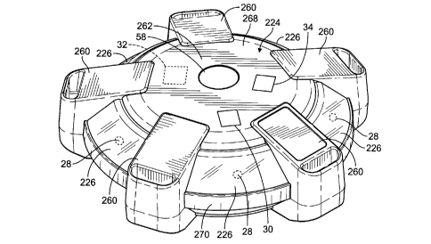
[0051] In an embodiment as shown in FIGS. 6-8, the housing 224 is
generally
circularly-shaped housing 224 and includes legs 260 extending from a central
hub 262.
In some embodiments that shape can be oblong to provide an asymmetric shape
around
any vertical axis, e.g., to provide a more uniform voltage detection in all
directions.
Other shapes can be used, e.g., square, rectangular, triangular, rhombus, etc.
At the
bottom 264 of the housing 224, see FIG. 8, the legs 260 can include bars 266,
e.g., for
providing access points to mounting mechanisms to mount the electric field
detector 20a
in the environment 10. For example, straps or ropes can be weaved through the
bars 266
to strap the electric field detector 20a to the environment 10. Additionally,
or
alternatively, the bars 266 can mate with corresponding female connectors
attached in
the environment 10, etc., to secure the electric field detector 20a to the
environment 10.
It will be appreciated, however, that additional or alternative mounting
mechanisms can
be used to mount an electric field detector 20a-d within an environment
10within the
scope of the disclosure. In an embodiment, the generally transparent or
translucent
covers 226 are positioned between the legs 260, and from a top 268 to a side
270 around
the perimeter of the housing 224, e.g., to be visible from any direction. In
some
embodiments, the covers 226 can be angled, e.g., from the top 268 to the side
270, to
provide a greater surface area of visible light.
[0052] In an embodiment, as shown in FIGS. 9-11, the electric voltage
detectors
320a-f can be stacked onto each other and onto a charging station 300 to
charge the
batteries 332. In an embodiment, the charging station 300 incudes a base 302
and
plurality of charge pads 304 provided thereon. Each electric voltage detectors
320a-f has
at least one contact 380 that extends through the housing 324 and is in
electrical
communication with the battery 332. During charging, the contact(s) 380 on the
lowermost electric voltage detector 320a engages the charge pad(s) 304 on the
charging
station 300. The contact(s) 380 on the stacked electric voltage detectors 320a-
f engage
one another to provide a continuous electrical path. When the charging station
300 is
activated, all of the batteries 332 of the electric voltage detectors 320a-f
are charged.
The electric voltage detectors 320a-f are removed from each other and the
charging
station 300 for use in the environment 10.
14
CA 3000713 2018-04-10
[0053] While the voltage threshold is described herein as a voltage
meeting a certain
voltage, the system could be modified to provide a warning if no voltage is
detected.
[0054] While particular embodiments are illustrated in and described with
respect to
the drawings, it is envisioned that those skilled in the art may devise
various
modifications without departing from the spirit and scope of the appended
claims. It will
therefore be appreciated that the scope of the disclosure and the appended
claims is not
limited to the specific embodiments illustrated in and discussed with respect
to the
drawings and that modifications and other embodiments are intended to be
included
within the scope of the disclosure and appended claims. Moreover, although the
foregoing descriptions and the associated drawings describe example
embodiments in the
context of certain example combinations of elements and/or functions, it
should be
appreciated that different combinations of elements and/or functions may be
provided by
alternative embodiments without departing from the scope of the disclosure and
the
appended claims.
CA 3000713 2018-04-10