Note: Descriptions are shown in the official language in which they were submitted.
CA 03000853 2018-04-03
WO 2017/063004
PCT/ZA2016/050039
Oxygenate Reduction Catalyst and Process
Field of the Invention
The invention relates to a catalyst for reduction of oxygenates, a use for
such a
catalyst, and processes using said catalyst. One such type of process is
reduction of
oxygenates in bio-oils produced from carbonaceous material of plant origin.
Background to the invention
Sourcing secondary materials from wood such as pulp, dissolving pulp, or
lignin
involves the thermochemical degradation through the use of moderate
temperatures
and chemicals readily reactive with wood. Research into developing other
materials
from wood such as fuel oils and chemicals has made use of similar
thermochemical
processes albeit at harsher conditions. The degree to which wood is thermally
and/or
chemically degraded will determine the type of products obtained. Subjecting
wood
to moderately high temperatures of between 400 C ¨ 500 C using fast heating
rates produces a fuel rich in valuable chemicals called pyrolysis oil.
zo Pyrolysis oil is difficult to process into more useful products mostly
due to its high
oxygen content. The presence of oxygenated substituents in the pyrolysis
oil
causes it to be more polar, making it readily soluble with water as well as
chemically
unstable. Another result of the high oxygen content is the presence of organic
acids,
which increases the acidity of pyrolysis oil.
Upgrading pyrolysis oil would therefore necessitate the removal of oxygen-
based
substituents.
In situ catalytic upgrading of pyrolysis oil has been used successfully to
deoxygenate
pyrolysis oil, thereby rendering it more useful. Deoxygenation occurs through
the
removal of oxygen in the form of either water (dehydration) or carbon oxides
(decarboxylation and decarbonylation). The hydrogen and/or carbon which form
the
backbone of pyrolysis oil are usually sacrificed during deoxygenation
reactions. With
hydrogen contributing a higher heating value to pyrolysis oil compared to
carbon, it
1
CA 03000853 2018-04-03
WO 2017/063004
PCT/ZA2016/050039
is preferred to achieve deoxygenation via decarbonylation/decarboxylation than
via
dehydration.
The Applicant has previously filed patent applications PCT/ZA2011/000067 for a
Fluidised Bed Pyrolysis Apparatus and Method which includes the use of a
combustion zone and a separate pyrolysis zone. Said apparatus includes two or
more hot particle fluidised beds, and one or more positive displacement
apparatus
for the transfer of hot particles between two or more of the beds, wherein one
or
more of the fluidised beds contains a combustion zone, and wherein one or more
of
the fluidised beds contains a pyrolysis zone. The apparatus is used for the
production of bio-oil in a process including pyrolysis of a carbonaceous bio-
mass,
optionally in the presence of a catalyst which may be a cracking catalyst such
as an
acid zeolite catalyst.
In a later patent application filed by the Applicant viz. PCT/ZA2014/000027,
an
alternative arrangement of the two fluidised bed reaction zones is claimed,
the two
fluidised bed zones may be in an annular arrangement wherein a first fluidised
bed
zone is substantially surrounded by a second fluidised bed zone with the
aperture
divider being located between the first and second fluidised bed zones. The
process
zo carried out therein once again produced bio-oil from biomass with the
possible use of
a catalyst in the pyrolysis process, and again the same catalysts are proposed
as in
the earlier patent application of the Applicant.
The Applicant has now identified one or more shortcomings of the bio-oil
products
produced by the process of the above two patent applications. In particular,
the bio-
oil is quite high in oxygenates and has an unacceptable Carbon to Oxygen ratio
and
a very low Hydrogen to Carbon ratio, while also having a lower than required
heating
value.
In an attempt to address the above shortcomings, after extensive research and
experimentation, the Applicant now proposes the invention described below as
at
least a partial solution thereto.
2
CA 03000853 2018-04-03
WO 2017/063004
PCT/ZA2016/050039
Summary of the Invention
In normal fast pyrolysis, bio-oil yield is maximum at temperatures around 500
C,
where approximately 60% of the biomass feed (on a dry basis) is converted to
bio-
Oil.
This bio-oil is highly reactive, partly due to the high oxygen content, which
is
characteristic of the original biomass.
The invention relates to two chemical looping deoxygenation catalyst systems
useful
for the reduction of oxygenates in bio-oil and other plant origin liquid
hydrocarbons,
such as oil seed derived bio-diesel.
In one embodiment a metal sulfide, is contacted with the bio-oil to produce
metal
sulfate by oxidising the sulfide to a sulfate while reducing the oxygen
content of the
bio-oil. This is a mechanism that effectively reduces the oxygen content thus
directly
producing a high quality pyrolysis-oil from a reduction-oxidation (redox)
reaction.
The reaction is exothermic at pyrolysis conditions and can be auto-thermal.
zo The metal sulfate may be reduced back to the sulfide form using carbon
or char as
the reducing medium, thereby removing the oxygen from the system as carbon
oxides, such as CO2.
In a second embodiment, layered double hydroxides (LDH) and its derivatives
are
used to decarboxylate crude bio-oil, achieving a similar effect as the sulfide-
sulfate
system, except this is an oxide-carbonate system, that again removes oxygen
from
the system as carbon oxides, such as CO2.
The reaction of the sulfide with the pyrolysis oil may take place separately
from the
reaction to reduce the sulfate back to the sulfide. This is referred to as
chemical
looping.
In the case of chemical looping, the reaction with bio-oil may take place in
conditions
similar to fast pyrolysis where the biomass to be pyrolysed is heated quickly
to 400
3
CA 03000853 2018-04-03
WO 2017/063004
PCT/ZA2016/050039
C ¨500 C in the presence of the sulfide, and the pyrolysis oil is recovered
from the
quenched vapours.
Alternatively, the reaction of the biomass with the sulfide may take place in
the liquid
phase, at conditions similar to hydrothermal liquefaction, such as 200 bar
pressure
and 300 C to produce a fuel oil. However, it is foreseen that the reduction
potential
of the sulfide in this system may make the hydrothermal liquefaction reaction
occur
at much milder conditions, thereby greatly reducing the capital expense of
such
reactors.
As an alternative to chemical looping, it may be possible to maintain
conditions
whereby the sulfate is immediately converted into sulfide by ensuring that CO
is
continuously produced by char that is present in the system.
In this case, the metal sulfide may be considered as a catalyst. The metal
sulfide or
sulfate may be a fluid at reaction conditions. The metal sulfide may be
attached to a
catalyst support so that the catalyst behaves heterogeneously as a solid under
reaction conditions, whether it is in a chemical looping system or in a
catalytic
system.
In the case of layered double hydroxide clays (LDH), carboxylic acids
intercalate
between the LDh layers, forming carbonates. These carbonates can be removed as
CO2 in a chemical looping system by raising the temperature, or may be
desorbed
as CO2 at normal pyrolysis reaction conditions, in which case the LDH acts as
a
catalyst.
The Mg-Al form of LDH may be more effective than any other catalysts reported
in
the literature. However, many other combinations may be equally effective,
where
the metal lattice than makes up the LDH may be chosen appropriately from Al,
Mg,
Ca, Na, K, Li, Cr, Mn, Fe, Co, Ni and combinations of these (e.g. Mg-Ca-Al).
Thus, according to a first aspect of the invention, there is provided a
catalyst system
and method for the use thereof, said catalyst system including:
4
CA 03000853 2018-04-03
WO 2017/063004
PCT/ZA2016/050039
a chemical looping catalytically active substance which is oxidised in the
presence of an oxygenate in a hydrocarbon or hydrocarbon containing
product, thereby reducing the amount of oxygenate therein, which oxidised
catalytically active substance is at least partially regeneratable by either
reducing it under reducing conditions to its original state, or through
calcining
thereof to release at least some of the captured oxygenate in the form of a
carbonate or the like thereby returning the catalyst to its active state for
removal of oxygenate from fluid hydrocarbons.
The hydrocarbon or hydrocarbon containing product may be a pyrolysis oil, such
as
bio-oil.
The bio-oil may be a fluid hydrocarbonmade by the pyrolysis of biomass.
The chemical looping catalytically active substance may be selected from
compounds, salts, and the like, of a Group I, Group II, transition metal, and
Group III
substance, with sulfur.
Thus, catalytically active substance may be a metal sulfide such as Na2S,
however,
zo
other compounds of sulfur may also provide adequate catalytic activity for
purposes
of the invention. The metal sulfide may be in the group Na, K, Ca, Mg, or from
the
transition metal group such as Mn, Fe, Co, Ni or Zn. The metal sulphide may be
selected from the group including metalloid sulfides and post-transition metal
sulfides,
The chemical looping catalytically active substance may be a layered double
hydroxide clay (LDH). In particular, the catalyst may be Mg-Al LDH.
However, many other combinations may be equally effective, where the metal
lattice
that makes up the LDH may be chosen appropriately from Al, Mg, Ca, Na, K, Li,
Cr,
Mn, Fe, Co, Ni, and other metals and metal combinations.
The LDH may be a calcined whereby the interlayer ions are removed and
hydroxides
convert to oxides. The calcined LDH is then a Layered Double Oxide (LDO).
5
CA 03000853 2018-04-03
WO 2017/063004
PCT/ZA2016/050039
This type of LDO is a loosely layered mixed oxide.
The catalytically active metal may be used at levels of between 1% and 99% by
mass on a solid catalyst support, typically around 10%.
In use, once oxidised from its reduced state, the looping catalyst system
reverts back
to its active state when treated in accordance with the invention i.e. by
reducing the
sulfate to sulfide or through calcining the LDH to release the CO2.
The invention extends to the use of a chemical looping catalyst system for the
catalytic deoxygenation of a biomass hydrocarbon, wherein the catalyst is
oxygenated in the presence of the oxygenate rich hydrocarbon thereby reducing
the
oxygenates in the hydrocarbon and the oxygen to carbon ratio, while increasing
the
hydrogen to carbon ratio thereof.
The use of the catalyst also reduces the quantity of the hydrocarbon as the
removal
of the oxygenates reduces the quantity of the hydrocarbon which was produced
in
the pyrolysis of the biomass.
zo The use of the catalyst may reduce the amount of carboxylic acids such
as acetic
acid and derivatives thereof in the liquid hydrocarbon.
The use of the chemical looping catalyst system may include the reducing
thereof
under reducing conditions in a combustion chamber or vessel under low oxygen
conditions, with oxygen or a suitable oxidant being injected or introduced
elsewhere
in the combustion chamber above the reducing zone.
The use of the chemical looping catalyst may include the calcining of the
oxidised
catalyst in the combustion chamber thereby to drive off the CO2 and regenerate
the
catalyst for re-use.
The combustion chamber may operate at a temperature used in a process of the
patent applications of the Applicant.
6
CA 03000853 2018-04-03
WO 2017/063004
PCT/ZA2016/050039
The catalyst can be used as a combustion-pyrolysis dual reaction zone process
for
the production of bio-oil from biomass, wherein at least some of the particles
used
for transferring heat within the process are catalyst particles in accordance
with this
invention.
The invention extends to the use of the catalyst system of the invention for
the de-
oxygenation of bio-diesel.
The invention extends further to the de-oxygenation of hydrocarbons, such as
pyrolysis oil, produced from pyrolysis of animal (abattoir) waste, or
otherwise
produced from animal waste which have high oxygenate levels.
Similarly, the invention extends to the use of the catalyst in the de-
oxygenation of
hydrocarbons produced by the pyrolysis of natural and/or synthetic rubber
and/or
plastics, for example tyres. These have low oxygen levels, but the catalyst
can still
refine the quality of these oils by reducing acidity. These are pyrolysis oils
that are
not derived from plants. (apart from the natural rubber component from latex).
The invention also extends to the use of the catalyst in the de-oxygenation of
zo hydrocarbons produced by the pyrolysis of lignin and cellulose.
According to a third aspect of the invention, there is provided a pyrolysis
process
including pyrolysis of a carbonaceous bio-mass wherein a first combustion zone
is
carried out in one or more combustion fluidised beds in which a particulate
material
including chemically looping deoxygenation catalyst particles is fluidised and
heated,
and a second pyrolysis zone carried out in one or more pyrolysis fluidised
beds in
which the hot particles, including the catalyst particles, heated in the
combustion
zone are used for pyrolysis of the bio-mass, said combustion zone being
operated at
a temperature of from 250 C to 1100 C, typically around 900 C, and the
pyrolysis
zone being operated at a temperature of from 250 C to 900 C, typically 450
C to
600 C, said catalyst particles being oxygenated in the pyrolysis zone in the
presence
of oxygenates in the pyrolysis oil and regenerated in the combustion zone
either by
calcining to drive off the carbon oxides, such as CO2, or by reduction to its
form
which is active for deoxygenation of the pyrolysis oil.
7
CA 03000853 2018-04-03
WO 2017/063004
PCT/ZA2016/050039
The catalyst particles are particles substantially as described above, for
example, a
metal sulfide or a LDH catalyst.
The catalyst particles are circulated between the combustion fluidised bed and
the
pyrolysis bed so that the catalyst loops between an oxidised and a reduced or
deoxygenation active state.
Fluidising gas and/or non-condensed vapours in the second fluidised bed zone
may
be recirculated and solid and liquid products may be removed as part of the
recirculation loop and a portion of the recirculated gas and/or non-condensed
vapours may be introduced into the second fluidised bed through nozzles.
Where there is a net production of gas in the recirculation loop, it may be
removed
as a purge stream.
The catalyst particles may pass through an aperture divider from the
combustion
zone into the pyrolysis zone.
zo The pyrolysis zone may be operated at or about atmospheric pressure.
The use of catalyst in the pyrolysis zone may allow more throughput of bio-
mass
because more carbon oxides such as CO2 are produced and therefore the process
will be less endothermic.
Description of Embodiments of the Invention
The invention will now be described, by way of non-limiting example only, with
reference to the accompanying diagrammatic drawings. In the drawings,
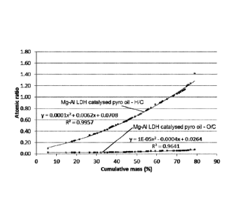
Figure 1 shows the results of the pyrolysis oil deoxygenation for a Mg-Al LDH
looping catalyst system;
8
CA 03000853 2018-04-03
WO 2017/063004
PCT/ZA2016/050039
Figure 2 shows the results of the pyrolysis oil deoxygenation for a Ca-Al LDH
looping
catalyst system;
Figure 3 shows the results of the pyrolysis oil deoxygenation for a zeolite
catalyst
system;
Figure 4 shows comparative data to Figures 1 to 3 for an uncatalysed pyrolysis
production of pyrolysis oil;
Figure 5 shows the composition analysis results of the pyrolysis oil
deoxygenation
for a Ca-Al LDH looping catalyst system;
Figure 6 shows the composition results of the pyrolysis oil produced without a
deoxygenation catalyst system of the invention;
Figure 7 shows the composition analysis results of the pyrolysis oil
deoxygenation
for a Mg-Al LDH looping catalyst system;
Figure 8 shows the composition results of a pyrolysis oil produced from
eucalyptus
zo without a deoxygenation catalyst system of the invention;
Figure 9 shows the composition results of a pyrolysis oil produced from
eucalyptus
with a deoxygenation catalyst system of the invention, Na2S on an alumina
support;
and
Figure 10 is a van Krevelen diagram relevant to the invention.
1. Experimental Work on Metal Sulfide Catalyst System
An experiment was used to demonstrate Na25 as a suitable oxygen scavenger
during the pyrolysis of wood. Eucalyptus grandis sawdust was mixed together
with
Na25 and placed in a muffle oven heated to 500 C. The char leftover was
compared
to the original sample using XRD analyses. The XRD analyses confirmed the
9
CA 03000853 2018-04-03
WO 2017/063004
PCT/ZA2016/050039
presence of sodium sulfate (Na2SO4) in the char. It is believed that the
oxygen used
to convert the sulfide ion into the sulfate ion was derived from oxygen
contained in
the wood.
A second experiment was completed, in which E. grandis mixed together with
Na2S
was pyrolysed in a nitrogen atmosphere using microwave radiation. The oil
formed
was found to be immiscible with water, and was remarkably different to
uncatalysed
pyrolysis oil produced on the same equipment.
io A third experiment made use of a pyro-GC-MS apparatus to pyrolyse 3
different
woody biomass feedstocks with Na2S on an alumina support, namely E. grandis,
bagasse, and lignin. GC-MS analysis of the products showed a notable
difference
when compared to uncatalysed pyrolysis oil produced using the same method.
A third experiment used Na2S mixed with E. grandis sawdust to produce
pyrolysis oil
via microwave pyrolysis. For comparison, untreated E. grandis was pyrolysed
using
the same method to obtain uncatalysed oil. The Na2S-derived pyrolysis oil
formed
black immiscible oil with a strong bitumen like smell, which readily separated
from
pyrolytic water that also formed during the process. In contrast the
uncatalysed oil
zo was fully miscible with water and smelled of burnt sugar, similar to
that of pre-
hydrolysate. The oil produced using Na2S had a calorific value 38.0 % higher
than
the uncatalysed oil.
Based on these experiments, it has been suggested that Na2S may be a suitable
chemical for use in a dual circulating fluidized bed (DCFB) system, an example
of
which is described in Applicants earlier PCT patent applications discussed
above.
This type of system is commonly used for pyrolysis oil production. In this
system the
bed material is transported cyclically from the pyrolysis fluidized bed to the
combustion fluidized bed and back again, taking with it any other solid
materials
present in the system (such as char, wood biomass or catalysts). Oxidation of
Na2S
to Na2SO4 would be achieved during pyrolysis. The Na2SO4 could then be
transported with the bed material and char to the combustion zone. The
reduction of
CA 03000853 2018-04-03
WO 2017/063004
PCT/ZA2016/050039
Na2SO4 to Na2S would then take place during combustion using residual carbon
as
char to reform Na2S. Na2S will then be transported back to the pyrolysis zone
again.
As can be seen from Figures 8 and 9, which are compositional analyses of
pyrolysis
oil produced from eucalyptus, by pyrolysis both without a deoxygenating
catalyst and
with a Na2S catalyst on an alumina support, the amount of acetic acid produced
in
the metal sulfide catalyst of the invention catalysed reaction is
substantially less than
that of the uncatalysed comparative analysis. As discussed below, the acetic
acid is
an indicator of the degree of deoxygenation of the bio-oil by the catalyst.
2. Experimental Work on LDH Catalyst System
Biomass was pyrolysed to pyrolysis oil using the following experimental set up
and
the bio-oil thus produced was analysed to determine, amongst other things, its
0/C
ratio, H/C ratio, Higher Heating Value (HHV) and composition (including acetic
acid).
Biomass used and sample preparation:
zo E. grandis was milled using a particle size reduced using cutting mill
to a particle size
distribution between 150 pm and 250 pm at a moisture content measured as 8.88
%.
Various oxygen scavenging catalysts were used for the experiment including Mg-
Al
LDH and Ca-Al LDH on alumina support at a 10% m/m loading.
For comparative purposes, an experiment was also conducted using zeolite as
the
catalyst and an uncatalysed experiment was conducted as well.
The results of these experiments are shown in Figures 1 to 7 below.
Equipment and methods used:
pyrolysis-GC/MS (Py-GC/MS) - Shimadzu multi-functional pyrolyser EGA/PY-3030D
from Frontier Labs, Japan
11
CA 03000853 2018-04-03
WO 2017/063004
PCT/ZA2016/050039
Evolved gas analysis (EGA-MS) was used to define the thermal desorption zone
using a thermal programme of 100 C to 600 C at 20 C/min
Sample sizes were in the range of 1.10 mg 0.1 mg
Samples reach pyrolytic temperatures in less than 20 ms
As can be seen from the figures, where no deoxygenation catalyst was used, the
0/C ratio for the pyrolysis oil produced was 0.48 with the H/C ratio being
1.74 while
the HHV was 23.2 MJ/kg. Where Zeolite was used at a temperature of 500 C, the
0/C ratio was 0.35, the H/C ratio was 1.58 and the HHV was 26.97 MJ/kg.
With the use of LDH catalysts of the invention, the picture is quite different
and the
results obtained for Mg-Al LDH are 0/C ratio of 0.02, H/C ratio of 1.69 and a
HHV of
over 40 MJ/kg. The results for Ca-Al LDH although slightly lower are still
superior to
that of the uncatalysed or zeoilte catalysed pyrolysis of biomass to bio-oil
with an
0/C ratio of 0.35, an H/C ratio of 1.65 and HHV of 28.8 MJ/kg.
In Figure 10 a van Krevelen diagram sets out the above ratios and the position
of the
zo bio-oil produced using the Mg-Al LDH catalyst as deoxygenating catalyst.
Again, the advantages of using the LDH catalyst system for deoxygenation of
the
pyrolysis oil is clear from Figures 5 to 7 and it can be seen that less acetic
acid is
produced when the LDH catalyst was used then when it was not used. This also
indicated a reduction in the yield of the pyrolysis oil from the biomass,
however, the
pyrolysis oil which is yielded is of a superior quality due to its reduced
oxygenate
levels.
GC-MS chromatograms of uncatalysed pyrolysis oil in Figures 5 to 7 show that
acetic acid which is typically formed from acetyl groups present in
hemicellulose is
present in pyrolysis oil as a result and the acetic acid peak clearly visible
and can be
seen to be reduced where the catalyst system of the invention was used.
12
CA 03000853 2018-04-03
WO 2017/063004 PCT/ZA2016/050039
By using LDH as a chemical looping catalyst system in pyrolysis, it always
decreases the product yield by stripping oxygen from the product. The same
applies
to the metal sulfide system.
13