Note: Descriptions are shown in the official language in which they were submitted.
- 1 -
INSERT FOR USE IN AN INJECTION MOLDING NOZZLE AND INJECTION
MOLDING NOZZLE WITH SUCH AN INSERT
The invention according to the preamble of claim 1 relates to an insert for
use in an injection
molding nozzle as well as an injection molding nozzle for an injection mold
with an insert
according to the invention per claim 15.
Injection molding nozzles, especially hot-channel nozzles, are used in
injection molds in order to
supply a fluid compound, such as a plastic material, at a given temperature
under high pressure
to a releasable mold insert. They usually have a material tube with a flow
channel which is
fluidically connected by an inlet opening to a distributor channel in a
distributor plate and
emerges by an outlet opening in the gate opening of the mold insert (mold
cavity).
So that the flowable material within the flow channel of the hot-channel
nozzle does not cool
down prematurely and harden, a heating device is provided, being placed or
arranged on the
outside of the material tube. Moreover, in order to ensure that the flowable
compound is held at a
uniform temperature up to the gate opening, a heat conducting sleeve made of a
high thermal
conductivity material can be inserted at the end side in the material tube,
being a continuation of
the flow channel and forming at the end side the outlet opening for the
injection molding nozzle.
In the case of an open nozzle, the heat conducting sleeve is usually designed
as a nozzle
mouthpiece and provided with a nozzle tip, terminating by its conical tip in
or shortly before the
plane of the gate opening. In the case of a needle valve nozzle, a tight seat
for a valve needle is
formed at the end side in the outlet opening of the heat conducting sleeve,
which can move back
and forth by means of a needle drive between an open and a closed position.
When processing abrasive materials or injection molding compounds which
contain abrasive
components, severe wear may occur on the heat conducting sleeve, especially at
the outlet
opening, so that the heat conducting sleeve or ¨ depending on the design ¨ the
entire hot-channel
nozzle needs to be replaced rather often. Especially in the case of needle
valve nozzles, damage
occurs to the tight seat for the valve needle, so that this can no longer be
moved precisely from
CA 3000911 2018-04-11
- 2 -
an open to a closed position during the periodic movement and the outlet
opening is no longer
tightly closed.
Furthermore, the individual components of an injection molding nozzle are
generally exposed to
an abrasive and adhesive wear. This wear is due to the fact that metallic
components rub against
other metallic components, without it being possible to use a lubricant, which
might contaminate
the injection molded products being produced.
In order to prevent wear, WO 2005/018906 Al proposes an insert which is
preferably made from
a wear-resistant material. This is arranged at the mold insert-side end of a
nozzle mouthpiece and
is designed to be lengthwise movable either in itself or together with the
nozzle mouthpiece. The
insert serves for protection of the nozzle mouthpiece against heavy wear and
optimizes the
needle guidance of needle valve nozzles, since it functions as a centering
body for both the valve
needle and for the nozzle.
One problem here is that the insert must constantly be joined tightly to the
nozzle mouthpiece or
a heat conducting sleeve. But often this cannot be ensured, so that solvent
for example contained
in the flowable compound can creep into the inserting area of the insert. Even
a slight leaking in
this area may decide whether the product can be sold or needs to be picked out
as a reject.
Furthermore, such inserts are usually adapted to be lengthwise movable, so
that the insert can
move between mold insert and nozzle during the operation. This results in
different bearing
surfaces of the insert against the nozzle mouthpiece or against the heat
conducting sleeve and
consequently undesirable overhangs at the articles being produced, which
furthermore entails
different temperatures.
The goal of the invention is to overcome these and other drawbacks of the
prior art and to create
a compact insert for an injection molding nozzle, which can be inserted with
no leakage into a
material tube, a nozzle mouthpiece, or a heat conducting sleeve of an
injection molding nozzle.
The insert should be easy and economical to produce. Furthermore, a
positioning of the insert
with respect to the injection mold should be easier and more precisely
achievable. Furthermore,
an optimal heat transfer should be possible from the injection molding nozzle
to the insert and
the insert should be interchangeable.
CA 3000911 2018-04-11
- 3 -
The main features of the invention are indicated in the characterizing passage
of claim 1 and
claim 15. Embodiments are the subject matter of claims 2 to 14.
In an insert for an injection molding nozzle, with an insert body in which at
least one flow
channel is formed with an inlet opening and an outlet opening, wherein the
insert body
comprises a neck section, an end section, and a flange projecting radially
with respect to the neck
section and the end section, the flange having a stopping surface facing the
outlet opening and a
surface facing the inlet opening, the invention proposes that the neck section
comprises a seal.
The seal has the effect that no leakage can occur between the insert and the
injection molding
nozzle. In this way, injection molded articles can be produced in constantly
high quality and
rejects can be minimized. The neck section serves for connecting to the
injection molding
nozzle, i.e., it is inserted for example in a heat conducting sleeve, a nozzle
mouthpiece or a
material tube of the injection molding nozzle. But it is also possible to
design the insert and the
neck section such that the insert is shoved by its neck section onto the heat
conducting sleeve,
the nozzle mouthpiece or the material tube. The seal of the insert is
constantly in contact by at
least one of its surface sections with the injection molding nozzle or its
components.
This is also enabled by the design wherein the seal of the insert is
configured as a sealing ring.
This can be produced easily and economically and placed on the neck section of
the insert. A
sealing ring furthermore enables an easy preassembly on the insert. It is
preferable that the inner
diameter of the sealing ring is adapted to the outer diameter of the neck
section of the insert, so
that for example a force locking and/or form fitting connection of the sealing
ring to the insert
can be accomplished. The sealing ring can moreover be preassembled on the
insert, without
other fastening elements being needed.
If the seal is fashioned as a sealing ring, a contour of the sealing ring may
be provided that
preferably has a uniform cross section over the overall circumference. In this
way, the insert with
sealing ring can be easily inserted into the injection molding nozzle, without
needing to observe
a particular orientation of the two components to one another. Furthermore,
such a sealing ring
can be produced easily and economically.
CA 3000911 2018-04-11
- 4 -
One important embodiment of the invention proposes that the seal forms a
positioning ring. In
this way, the seal additionally provides a constantly correct and exact
positioning of the insert
relative to the injection molding nozzle and to the mold insert (mold cavity),
namely, to the edge
of the article being produced. The preferably lengthwise movable insert is
thus situated in the
installed state constantly in the same position in the mold and the
temperature control of the
nozzle only has to be adjusted once. Neither do any additional components need
to be used for a
correct positioning, for example ensuring a minimum spacing between the flange
of the insert
and the injection molding nozzle. The handling and the installing of the
injection molding nozzle
is in this way significantly easier. If the insert at the same time is
designed as a valve needle
guide and valve needle sealing element, the solution according to the
invention ensures a
constantly precise orienting and guiding of the valve needle.
In a preferred modification it is proposed that the seal has a substantially
rectangular cross
section. Preferably the long side of the rectangle extends in the longitudinal
or axial direction to
the neck section. A sealing ring so configured can be produced easily and
enables a good sealing
action.
Preferably, the substantially rectangular cross section of the seal comprises
at least one concave
and/or convex formation. In this way, both the sealing function and the
positioning function are
realized in that the seal when mounting the injection molding nozzle can be
deformed to a
defined degree and can adapt to the given sealing surfaces of the injection
molding nozzle and
the insert.
A preferred embodiment proposes that the sealing ring has a partial circular
formation on at least
one of the long sides. Preferably, two partial circular formations are
arranged on opposite long
sides of the rectangular cross section surface.
If this at least one formation of the substantially rectangular cross section
is formed on the
outside, this corresponds to a convex formation. This makes possible an
automatic orienting of
the sealing ring when bringing together the sealing ring with the insert and
the injection molding
nozzle. The seal lies at least by this convex formation against the neck
section and/or in the
installed state against a surface of the injection molding nozzle. The convex
formation can
CA 3000911 2018-04-11
- 5 -
furthermore improve the sealing effect, since in the final mounted state of
the injection molding
nozzle an increased force acts on this region of the seal.
Alternatively, at least one concave formation is preferably provided. In this
configuration, at
least one of the long surfaces of the rectangular cross section is formed to
be partly circular on
the inside. In this way, a recess is produced in the sealing ring, which
enables a better adapting of
the seal when bringing together the insert with an injection molding nozzle.
Preferably, the seal has two convex or two concave formations, the formations
being formed on
opposite long sides of the seal or the sealing ring. In this way, a very good
sealing effect can be
achieved.
Another important embodiment of the invention proposes that the seal comprises
at least one
cutting and/or pinching edge in the longitudinal direction of the insert. This
cutting and/or
pinching edge is designed in its wall thickness and length so that it becomes
deformed upon
mounting the injection molding nozzle and upon heating the mold in the plastic
region so that an
optimal sealing is achieved and at the same time an exact positioning of the
insert relative to the
injection molding nozzle is assured, without the material tube, the heat
conducting sleeve or the
nozzle mouthpiece of the injection molding nozzle suffering damage. The
deformed region of
the seal, i.e., the cutting and/or pinching edge, is consequently both a seal
and a spacer, which
exactly positions the insert so that it always lies flush with the surface of
the article being molded
in the injection region.
It will be noticed that the cutting and/or pinching edge forms an extension of
the seal in the
longitudinal direction of the insert, having a cross section which tapers as
compared to the
rectangular cross section of the seal and which extends preferably in the
direction of the flange.
This extension is preferably formed on the short side of the substantially
rectangular cross
section and therefore serves for the exact positioning of the seal and thus
the insert relative to the
injection molding nozzle and thus also to the mold insert. The extension acts
as a cutting and/or
pinching edge when installing the insert in the injection molding nozzle and
is more easily
deformed during its mounting than for example the rectangular main cross
section of the seal,
which accomplishes an increased sealing action.
CA 3000911 2018-04-11
- 6 -
In one preferred configuration, the seal is arranged on an outer circumference
of the neck
section. In this way, the seal may be quickly and conveniently mounted on the
insert.
It is further favorable to the function of the seal when a circumferential
recess for the seal is
formed in the outer circumference of the neck section. Hence, it is always
held securely in place.
Thanks to the circumferential recess, moreover, a correct and precise
positioning of the seal is
assured. The seal cannot slip. Instead, it is held with form fit in the
circumferential recess.
In a further configuration, the seal is arranged adjacent to the radially
projecting flange.
Moreover, it is preferably in contact with the surface of the flange facing
the inlet opening, in
which case the extension in the form of the cutting and/or pinching edge is
preferably in contact
with the surface of the flange.
Thus, the seal is braced by the extension or the cutting and/or pinching edge
against the flange,
which ensures that the insert is always positioned correctly inside the mold.
Furthermore, this
also assures a constantly correct positioning of the insert when installing it
in the injection
molding nozzle, so that an optimal sealing and an optimal temperature control
of the flowable
compound can be assured during its movement through the flow channel.
The seal preferably lies in the lower region of the neck section, the lower
region of the neck
section being formed adjacent to the radially projecting flange.
Advantageously, the seal is in
contact at least for a portion with the surface of the flange facing the inlet
opening.
If the neck section is inserted into or onto a heat conducting sleeve, a
nozzle mouthpiece or a
material tube, this configuration enables on the one hand a precise contact
between the two
components and on the other hand a reliable sealing effect. The sealing effect
of the seal can be
utilized in the best possible way both in the radial and in the axial
direction.
In one preferred configuration, the seal is deformable. In this way, the best
possible sealing
effect can be achieved when producing the insert with the seal and when
assembling the insert
with the injection molding nozzle. An optimal sealing effect is achieved in
that forces of
deformation act on the seal, so that the seal is pressed against the free
space between insert and
injection molding nozzle and is thus adapted.
CA 3000911 2018-04-11
- 7 -
Preferably, the thickness of the seal in the radial direction is designed such
as to achieve the best
possible deformability.
In one preferred embodiment, the seal comprises a metallic material. Metallic
materials can be
chosen flexibly according to the desired requirements. Especially preferred is
copper for
example, since this has a good deformability while at the same time having
good heat
transmission.
If, for example, a copper seal is used, the seal can on the one hand be
deformed when assembling
the insert with the injection molding nozzle such that an optimal sealing
effect is obtained, and
on the other hand copper has good thermal conductivity, so that for example
heat can be
transferred from the heat conducting sleeve to the insert and thus the
flowable compound is
optimally temperature-controlled up to the outlet opening.
Alternatively, the seal comprises plastically deformable materials, especially
plastics, which are
resistant to solvents and heat, or ceramics, with good deformation properties
and high thermal
conductivity.
In one preferred configuration, the flange has a thread on a radially outer
surface. In this way, the
insert can be easily mounted in or removed from an injection molding nozzle.
In an advantageous configuration of the invention, the insert is rotationally
symmetrical to a
longitudinal axis. This form of the insert is easy and economical to produce,
and it can also
easily be mounted in the injection molding nozzle, since no special
orientation of the insert needs
to be produced.
In a preferred embodiment it is provided that the insert body is two-piece.
Preferably the insert
body comprises a first part and a second part, wherein the first part is
formed substantially by the
neck section and the second part substantially by the end section. It is
preferably provided that
the first part is made from a high thermal conductivity material and extends
from the neck
section of the insert body as far as a boundary surface and the second part is
made from a second
material, which is different from the high thermal conductivity material of
the first part, wherein
CA 3000911 2018-04-11
- 8 -
the second part extends from the boundary surface as far as the end section of
the insert body,
and wherein the first part and the second part are joined to each other in
and/or along the
boundary surface.
In this way, it is possible to combine several material properties in only a
single component,
which is inserted for example into the lower, mold cavity-side end of a
material tube or a heat
conducting sleeve of the injection molding nozzle, and to utilize them for the
injection molding
nozzle and the flowable material to be processed, without requiring and having
to install several
different components. The different materials can be chosen and combined in
accordance with
the requirements. If the first part of the insert is made from a high thermal
conductivity material,
the heat generated by a heating of the injection molding nozzle can be taken
as far as possible up
to the gate opening.
The second part, on the other hand, made from a second material, can be
produced for example
from a wear-resistant material, in order to reduce the wear on the insert and
thus increase the
service life of the injection molding nozzle, especially when the second part
of the insert forms
the tight seat for a valve needle.
Preferably, the second material has a lesser thermal conductivity than the
high thermal
conductivity material.
The first part and the second part of the insert can advantageously be made as
separate parts,
which are precisely and firmly joined together after their fabrication.
Alternatively, it is also
possible to produce at first a rough blank from a composite of the high
thermal conductivity
materials and the third material and then fabricate the insert from this
composite. Thanks to the
connection of the two parts of the insert consisting of two different
materials with an additional
coating, the advantageous properties of the materials can be chosen precisely
and utilized in the
best possible way in the smallest structural space. A cost and maintenance
intensive installation
of different single parts is avoided. Likewise, no costly sealing elements or
sealing surfaces are
needed between the two parts, which might result in leakage at or in the
injection molding nozzle
or in the mold. Instead, the two parts are constantly joined together firmly
and the insert forms a
unitary component in its handling with minimal dimensions.
CA 3000911 2018-04-11
- 9 -
The connection extends by virtue of the boundary surface between the different
materials used,
so that although the properties of several materials are combined in a single
component, at the
same time a clear demarcation of materials is ensured on the different parts.
A mixing of the two
substances outside the boundary surface is prevented. This contributes to the
optimal and precise
utilization of the materials when using an insert in an injection molding
nozzle.
Embodiments of the invention propose that the first part and the second part
are joined together
by integral bonding, form fitting, or frictional locking. With an integrally
bonded connection,
minimum dimensions can be achieved. But mechanical connections in the form of
a form fitting
or a frictional locking are also conceivable, for example by interlocking,
screw fastening, press
fitting or shrink fitting.
Preferably, the first part and the second part are joined together with
integral bonding at the
boundary surface, especially welded, soldered, or glued.
Due to the limited structural space, it is especially advantageous when the
first and second part
are joined together with integral bonding by means of welding, preferably by
means of diffusion
welding or laser welding.
Welding has proven to be the optimal method for connecting the first and the
second part,
because the first and the second part are usually formed from a metallic
material and welding can
produce a reliable and long-lasting stable connection between the parts.
Diffusion welding in
particular has benefits over other welding methods. The quality of the welded
connections is
exceptionally high. A pore-free, tight material composite is formed, meeting
the highest
mechanical, thermal and corrosion requirements. With diffusion welding, it is
not necessary to
use any added material, so that the seam has no foreign alloy components and
thus possesses
properties similar to those of the base materials, when properly designed.
Furthermore, thanks to
no molten fluid phase in the joining process, a highly precise and contour-
true welding can be
assured.
Alternatively, the first part can be joined to the second part by means of a
mechanical connection
arrangement. For this purpose, a locking connection, a screw connection, a
press fitting or a
bayonet connection can be used, among others. The two parts can also be joined
together by
CA 3000911 2018-04-11
- 10 -
shrink fit. All of the aforementioned types of connection have the benefit
that such a connection
of the first part to the second part is firm and tight.
It is especially advantageous when the second material of the second part is a
wear-resistant
material. In this way, it is possible to reduce the wear on the insert ¨ for
example in the region of
a needle guide ¨ on account of the repeated sliding of the valve needle along
the inner walls of
the flow channel during active operation of the injection molding nozzle. At
the same time, a
high thermal conductivity design of the first part of the insert, which can be
arranged for
example on a heat conducting sleeve, ensures an optimal temperature
distribution in the gate
region.
It has proven to be advantageous when the thermally conductive material and
the second
material have a high thermal expansion. Thanks to the use of a material with
high thermal
expansion, the insert expands specifically during the heating of the injection
mold, so that after
reaching the operating temperature of the injection molding nozzle the insert
is optimally
clamped between material tube and/or heat conducting sleeve on the one hand
and mold insert on
the other hand and forms a durable tight arrangement.
In another advantageous design, the material of the first part and the
material of the second part
have an identical or nearly identical coefficient of expansion.
If the coefficients of expansion of the two parts of the insert are different,
the difference between
the coefficients of thermal expansion of the thermally conductive and the
second material takes
into account the elastic capacities of the connection between the first and
the second part, so that
the two parts of the insert are always joined together durably and firmly.
In a special embodiment, the wear-resistant material is a tool steel. This is
distinguished by good
wear protection properties. Tool steel is more economical than other materials
with comparable
wear protection properties. In particular, a tool steel with low thermal
conductivity may be
advantageous, because in this case there is a thermal separation of the
plastic melt from the mold
insert of the injection mold, which prevents a premature cooldown of the
plastic melt in the
region of the second section. The additional coating of a material with a low
thermal
conductivity additionally supports this effect.
CA 3000911 2018-04-11
- 11 -
Alternatively, a ceramic which is distinguished by high wear resistance and
low thermal
conductivity could also be used as the wear-resistant material.
A further embodiment of the invention proposes that the boundary surface along
which the first
part is connected to the second part extends perpendicular to or obliquely to
the longitudinal axis
of the insert body. In particular, it is proposed that the boundary surface
along which the first
part is connected to the second part extends solely perpendicular to or
obliquely to the
longitudinal axis of the insert body
This produces, for example, a disk-shaped boundary surface with minimal
expansion. Thanks to
the perpendicular run of the boundary surface, an optimal connection can be
produced between
the first and the second part.
Alternatively to this, the boundary surface may also extend obliquely to the
longitudinal axis of
the insert body, for example when a larger boundary surface is desired. The
latter may be
conically formed, for example. Thanks to a boundary surface oriented obliquely
to the
longitudinal axis, an integrally bonded connection can be strengthened in
particular, since in this
case a larger section is available as boundary surface.
In another special embodiment, the flange is preferably formed by the first
part or the second
part. In either variant, the flange is formed uniformly from one material and
exhibits the
properties of the respective material. In this way, the flange may either
continue the heat
conducting function of the neck section, for example, or enlarge the region of
the end section
which is protected by the wear-resistant material.
According to another embodiment, the flange is formed by the first part and
the second part. In
this way, the properties of the two materials can be combined optimally in the
narrowest space.
Since the flange functions primarily as a supporting flange, it comprises both
regions having
contact with the mold insert and regions which may lie against the material
tube, the nozzle
mouthpiece and/or the heat conducting sleeve, as required. Different
requirements must be
fulfilled in the two regions of the flange. While the temperature in the
transitional region
between flange and first section is constantly maintained high, at the same
time the heat transfer
CA 3000911 2018-04-11
- 12 -
from the material tube, the nozzle mouthpiece or the heat conducting sleeve to
the mold insert is
minimal. Furthermore, a more intense wearing must be assumed precisely at the
contact surfaces,
so that in these places a stronger wear protection is assured. Since the two
parts of the different
materials form the flange, these opposite requirements can be fulfilled in a
single component in
the smallest space. This also holds in particular for the overall insert.
According to another advantageous embodiment, the insert forms a centering
body for a valve
needle of an injection molding nozzle. In this case, the insert forms in the
first part and/or in the
neck section a flow channel wall which tapers conically in the direction of
the flange. Such a
wall centers the valve needle during the closing movement, so that the free
end of the valve
needle can always run precisely in its tight seat. Preferably, the trend of
the flow channel in the
region of the first part and/or neck section is such that the valve needle is
oriented already to the
gate opening of the insert. Thus, excessive wear on the valve needle is
additionally avoided.
According to another important embodiment, the second part forms a tight seat
for a valve
needle of an injection molding nozzle. This can be accomplished, for example,
by adapting the
diameter of the flow channel in the region of the end section to the
circumference of the valve
needle of a needle valve nozzle. Corresponding embodiments have the advantage
that the wear
on the insert in the region of the end section, caused by repeated sliding of
the valve needle along
the surfaces of the flow channel, is significantly reduced.
According to another embodiment, the second part of the insert is configured
to form, with its
front end, a section of a wall of a mold cavity.
Furthermore, the invention relates to an injection molding nozzle for an
injection mold with an
insert according to the invention. The injection molding nozzle may be either
a hot-channel
nozzle or a cold-channel nozzle. The insert may find use both in injection
molding nozzles with
open gate and nozzle tips and in injection molding nozzles with heat
conducting sleeve and
needle valve closure.
Injection molding nozzles with the insert according to the invention will
profit from the seal,
which is arranged at the neck section of the insert, so that an improved
sealing effect can be
achieved. Basically, the insert protects the injection molding nozzle against
wearing processes
and ensures a long-lasting, low-maintenance use of the injection molding
nozzle.
CA 3000911 2018-04-11
- 13 -
Furthermore, the insert can be produced in a simple and economical manner. The
positioning of
the insert in the injection mold can also be done more precisely.
When the injection molding nozzle is a needle valve nozzle, this has the
further advantage that
the insert additionally functions as a centering body, because the needle is
guided precisely and
with stable position inside the insert. Thanks to the improved positioning,
the needle guidance
can also be further improved. This avoids damage to the valve needle, but also
reduces wear
processes on the injection molding nozzle.
The injection molding nozzle itself may comprise different components in
different
embodiments. All embodiments of the injection molding nozzle comprise a
material tube, in
which at least one flow channel is formed, which is fluidically connected to a
mold cavity of the
injection mold formed by at least one mold insert.
Depending on the embodiment, the injection molding nozzle furthermore has a
heat conducting
sleeve, which can be designed as a nozzle mouthpiece. The heat conducting
sleeve is inserted
into the material tube at the end, or mounted on the material tube, and it
forms the outlet opening
for the flow channel. The heat conducting sleeve is made from a high thermal
conductivity
material so that the melt can be fed at constant high temperature to the mold
insert, without
forming a so-called cold plug.
The insert according to the invention is preferably arranged at the mold
insert-side end of the
material tube, wherein the seal is arranged between the insert and the mold
insert side-end of the
material tube. In one preferred modification it is proposed that the injection
molding nozzle
comprises a heat conducting sleeve at whose mold insert-side end is situated
the insert with the
seal, the seal being arranged between the insert and the mold insert-side end
of the heat
conducting sleeve. The insert may be inserted into or placed on the material
tube or the heat
conducting sleeve. The neck section of the insert is adapted thereto
accordingly. Furthermore,
the seal is preferably adapted to the neck section of the insert and the mold
insert-side end of the
material tube or the heat conducting sleeve. The insert is furthermore formed
separate from the
other components of the injection molding nozzle and constitutes a separate
component of the
injection molding nozzle.
CA 3000911 2018-04-11
- 14 -
It has proven to be especially advantageous when the insert during the
operation of the injection
molding nozzle is firmly installed in the material tube, the nozzle mouthpiece
or the heat
conducting sleeve, yet has an interchangeable design. That is, the insert is
clamped or otherwise
secured between the material tube and the mold insert, the nozzle mouthpiece
and the mold
insert, or between the heat conducting sleeve and the mold insert at least as
soon as the mold has
reached its operating temperature. The insert occupies a predefined position
thanks to the seal, in
which an optimal heat transfer is made possible from the injection molding
nozzle to the insert.
In this way, an optimal temperature control of the flowable compound as far as
the mold insert
can be assured.
Furthermore, it is possible to install and remove the insert quickly and
conveniently. No tools or
other aids are required for this. Neither do any additional parts or aids need
to be provided for the
securing of the insert in the injection molding nozzle, such as screw threads,
threaded sleeves or
the like on the insert itself or in the injection molding nozzle, because the
insert is reliably
secured during the operation of the injection molding nozzle. Even so, the
insert can always be
replaced quickly and economically.
Furthermore, it is advantageous when the neck section with the seal is form
fitted at least for a
portion to the material tube, the nozzle mouthpiece or the heat conducting
sleeve and/or the end
section is form fitted at least for a portion to the mold insert. Thanks to
the form fitting, a tight
connection is achieved, thereby preventing the melt from getting into
interstices. Thus, the insert
with the other parts of the injection molding nozzle forms a plug-in system,
from which the
insert can be easily removed by pulling out without the use of tools, yet at
the same time the
injection molding nozzle is reliably secured by for example clamping during
its operation.
In one preferred embodiment, the insert is arranged at the mold insert-side
end of the material
tube, the nozzle mouthpiece or the heat conducting sleeve, the mold insert-
side end of the
material tube, the nozzle mouthpiece or the heat conducting sleeve having a
recess, with which
the seal of the insert engages. This recess is preferably situated near the
mold insert-side end or
at the mold insert-side end of the material tube, the nozzle mouthpiece or the
heat conducting
sleeve. In this way, the insert with the seal can be shoved into or placed on
the corresponding
component of the injection molding sleeve. The seal is arranged between the
neck section of the
CA 3000911 2018-04-11
- 15 -
insert and the recess of the material tube, the nozzle mouthpiece or the heat
conducting sleeve
and is deformed according to the force acting on it, ensuring the best
possible sealing between
the insert and the injection molding nozzle.
Furthermore, such an arrangement is simple and economical to produce and
install. The seal
produces the most precise possible positioning of the components, so that a
good temperature
control of the flowable compound is made possible up to the mold insert.
Further features, details and benefits of the invention will emerge from the
wording of the claims
as well as the following description of sample embodiments with the aid of the
drawings. There
are shown:
Fig. 1 a schematic longitudinal section through a first embodiment of an
insert according to the
invention,
Fig. 2 a schematic longitudinal section through another embodiment of an
insert according to
the invention,
Fig. 3 a schematic longitudinal section through another embodiment of an
insert according to
the invention,
Fig. 4 a schematic longitudinal section through yet another embodiment of an
insert according
to the invention.
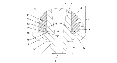
The insert designated generally as 1 in Fig. 1 is intended for use in an
injection molding nozzle
of an injection mold (not otherwise represented). The injection molding nozzle
has a material
tube and a heating device, while a heat conducting sleeve 6 is installed in
the end of the material
tube which is facing a mold insert of the injection mold. The latter
accommodates the insert 1 in
lengthwise movable manner in the cold state of the injection mold.
The insert 1 has an insert body 2, in which a flow channel 3 is formed with an
inlet opening (not
visible) and an outlet opening 4. The inlet opening stands in fluidic
communication with a melt
channel formed in the material tube and the heat conducting sleeve. The outlet
opening 4
emerges ¨ if the injection molding nozzle is mounted in the injection mold ¨
directly in a gate
opening in the mold insert of the injection mold (also not shown).
CA 3000911 2018-04-11
- 16 -
The insert 1 moreover has a neck section 5, for introducing or inserting the
insert body 2 into the
injection molding nozzle, namely into the heat conducting sleeve 6, while the
neck section 5 is
preferably inserted or press fitted into the heat conducting sleeve 6. At its
end opposite the neck
section 5, the insert 1 has an end section 7. By this end section, the insert
1 is inserted into the
mold insert of the injection mold.
Between the neck section 5 and the end section 7 is formed a flange 8
projecting radially with
respect to the neck section 5 and the end section 7. This has a stopping
surface 9, which faces the
outlet opening 4, and a surface 10, which faces the inlet opening. By the
stopping surface 9 the
insert 1 can be braced against or on the mold insert, when the injection
molding nozzle and the
injection mold are mounted. The surface 10 on the flange 8 serves as a
supporting surface or
abutment for a seal 11, which is formed on the neck section 5 of the insert.
It can be seen in Fig. 1 that the seal 11 is arranged preferably in the lower
region of the neck
section 5, the lower region of the neck section 5 being formed adjacent to the
radially projecting
flange 8. The seal 11 sits like a closed ring on the outer circumference 51 of
the neck section 5.
The latter is provided with an encircling circumferential recess 52 in this
region, so that the seal
lilies in the circumferential recess 52. The latter is bounded by a step 53 in
the longitudinal
direction L of the insert body 2 at its end 53 facing the inlet opening of the
flow channel 3, while
the end of the circumferential recess 52 facing the outlet opening 4 is
bounded by the flange 8
and its surface 10.
The seal 11 has a main body 12 with a substantially rectangular cross section
as well as an
extension 16, which is tapered relative to the rectangular cross section and
by which the seal 11
is braced against the flange 8. The extension is therefore situated on the
short side 17 of the
rectangular cross section of the seal. In each of the long sides 15 of the
rectangular cross section
of the seal 11 there is produced a concave formation 14. These may be formed
lying opposite
each other. The formations 14 may also lie at different heights in the
longitudinal direction L.
The seal 11, preferably made from a deformable material, such as a metal, thus
forms at first a
sealing ring for the insert 1, which seals off the insert body 2 against the
heat conducting sleeve 6
when the insert 1 is inserted into the heat conducting sleeve 6 and the
injection molding nozzle is
mounted in the injection mold. As soon as the latter has reached its operating
temperature, the
CA 3000911 2018-04-11
- 17 -
main body 12 of the seal 11 and the extension 16 are deformed to such an
extent that a durable
reliable seal is created between the insert 1 and the heat conducting sleeve.
The extension 16 forms in this case a cutting and/or pinching edge, which is
designed such in its
dimensions that it is deformed by the flange edge in the plastic region. At
the same time, the
concave formations 14 ensure that the main body 12 of the seal 11 can also be
deformed
specifically between the neck section 5 of the insert body 2 and the heat
conducting sleeve 6, so
that a durable reliable seal is created between the insert 1 and the heat
conducting sleeve 6. The
heat conducting sleeve 6 is not damaged in this process, since the extension
16 cuts only into the
flange 8 of the insert body 1.
The sealing ring thus creates a durable reliable seal in the insulation region
of the injection
molding nozzle, i.e., the plastic being processed or its components can no
longer get through
between the insert 1 and the heat conducting sleeve 6 to the outside and into
the forechamber
region ¨ filled or unfilled depending on the area of application - of the
injection molding nozzle.
The insert 1 thus not only protects against wear during the processing of
abrasive media, but also
ensures a durable reliable sealing.
Yet the seal forms not only a sealing ring, but also a positioning ring.
Once the injection mold has reached its operating temperature, the seal 11
forms with its main
body 12 and the extension 16 a defined end stop between the flange 8 and the
heat conducting
sleeve 6. The seal 11 in this process is braced by the extension 16 inside the
circumferential
recess 52 against the surface 10 of the flange 8. The insert 1 thus can no
longer be moved
inadvertently in the direction of the material tube. Instead, it forms a
defined end stop for the
injection molding nozzle relative to the mold insert of the injection mold,
wherein the insert 1 is
positioned always flush with the surface of the article being molded. This
effectively prevents
unwanted overhangs at the boundary surface of the article.
The seal 11 thus ensures an always exact positioning of the insert 1 and thus
the injection
molding nozzle in the mold.
CA 3000911 2018-04-11
- 18 -
It may be provided that the insert 1 in the region of the extension 16 has an
indentation 18
adapted to the extension 16, into which the extension 16 can be pressed when
installed in an
injection molding nozzle 6. In this way, the sealing effect can be further
enhanced, as can the
precision of the positioning.
Fig. 2 shows another embodiment of an insert 1 according to the invention with
a seal 11 on the
neck section 5.
The seal 11 also here has a main body 12 with a substantially rectangular
cross section as well
as an extension 16, which is tapered relative to the rectangular cross section
and by which the
seal 11 is braced against the flange 8. The extension is situated on the short
side 17 of the
rectangular cross section of the seal.
By contrast with the embodiment of Fig. 1, however, no concave formations 14
are made in the
long sides 15 of the rectangular cross section of the seal 11. Convex
formations 19 are provided
on the long sides 15. These may be formed opposite each other. The elevations
19 may also lie at
different heights in the longitudinal direction L.
The seal 11, preferably made from a deformable material, such as a metal, thus
forms a sealing
ring for the insert 1, which seals the insert body 2 against the heat
conducting sleeve 6 when the
insert 1 is installed in the heat conducting sleeve 6 and the injection
molding nozzle is mounted
in the injection mold. Once this has reached its operating temperature, the
main body 12 of the
seal 11 with the formations 19 and the extension 16 are deformed to such an
extent that a durable
reliable sealing is produced between the insert 1 and the heat conducting
sleeve.
The extension 16 forms in this case a cutting and/or pinching edge, which is
designed such in its
dimensions that it is deformed by the flange edge in the plastic region. The
latter also holds for
the formations 19, which are pressed with an increased force against the neck
section 5 and the
heat conducting sleeve 6.
At the same time, the sealing ring 11 here also forms a positioning ring,
which holds the insert 1
in a defined position with respect to the heat conducting body 6.
CA 3000911 2018-04-11
- 19 -
Fig. 1 and Fig. 2 both show embodiments in which the insert 1 according to the
invention is
installed in an injection molding nozzle, with the insert 1 sitting in a heat
conducting sleeve 6.
But the insert may also be inserted directly into the material tube or into a
nozzle mouthpiece of
the injection molding nozzle ¨ depending on the application and the design of
the injection
molding nozzle. In this case, the neck section 5 preferably sits with slight
movement play in the
injection molding nozzle.
Alternatively, it is also possible to configure the insert 1, especially the
neck section, so that it is
placed on an outer circumference of the heat conducting sleeve 6. The same
holds for the
mounting of the insert 1 directly on the material tube or on a nozzle
mouthpiece.
For the receiving of the seal 11 in the heat conducting sleeve 6 there is
provided a recess 22,
whose inner wall (not otherwise indicated) forms a sealing surface.
This recess 22 is preferably adapted to the seal 11 or the sealing ring 12.
Thus, the recess 22 may
be formed as an encircling ring with a substantially rectangular cross
section.
Fig. 3 and 4 each show a longitudinal section through another preferred
embodiment of an insert
1 according to the invention. In both Fig. 3 and 4, the insert body 2 is two-
piece. The insert body
2 comprises a first part 23 and a second part 24. The first part 23 is formed
substantially by the
neck section 5 and the second part 24 is formed substantially by the end
section 7. It is preferable
for the first part 23 to be made from a high thermal conductivity material and
to extend across
the neck section 5 of the insert body 2 as far as a boundary surface 25. The
second part 24 is
made from a second material and extends from the boundary surface 25 across
the end section 7
of the insert body 2. The two parts 23, 24 are joined together in and/or along
the boundary
surface 25.
Fig. 3 shows that the boundary surface 25 extends between the first part 23
and the second part
24 perpendicular to the longitudinal axis L of the insert body 2.
Fig. 4 shows an alternative configuration of the boundary surface 25. Here,
the boundary surface
25 extends between the first part 23 and the second part 24 obliquely to the
longitudinal axis L of
the insert body 2.
CA 3000911 2018-04-11
- 20 -
All features and advantages emerging from the claims, the specification, and
the drawing,
including design details, spatial arrangements, and method steps, may be
significant to the
invention both in themselves and in the most varied of combinations.
CA 3000911 2018-04-11
- 21 -
List of reference numbers
1 Insert
2 Insert body
3 Flow channel
4 Outlet opening
5 Neck section
51 Outer circumference
52 Circumferential recess
53 End
54 End
6 Heat conducting sleeve
7 End section
8 Flange
9 Stopping surface
10 Surface
11 Seal
12 Sealing ring
13 Depression
14 Concave formation
15 Long sides of seal 11
16 Extension / cutting/pinching edge
17 Short side of seal 11
18 Indentation
19 Convex formation
22 Recess
23 First part
24 Second part
25 Boundary surface
Longitudinal axis of insert 1
CA 3000911 2018-04-11