Note: Descriptions are shown in the official language in which they were submitted.
CA 03000939 2018-04-03
WO 2017/062868 PCT/US2016/056132
CUSTOM EARBUD SCANNING AND FABRICATION
CROSS-REFERENCE TO RELATED APPLICATIONS
[001] The current application is related to/claims priority under 35 U.S.C.
365 to U.S.
Provisional Application No. 62/239,811 filed October 9, 2015, the contents of
which are hereby
incorporated by reference in its entirety.
FIELD
[002] The subject matter described herein relates to producing earbuds and
earbud adapters
customized to an individual ear.
BACKGROUND
[003] Earbuds must be comfortable and provide a snug fit to provide the best
sound quality
and reduce ambient noise. To provide a comfortable and snug fit, customized
earbuds may be
produced that are based the actual shape of an ear. Traditional methods of
determining the actual
shape of an ear cavity include creating an impression of the ear canal.
Creating or taking an
impression includes injecting a material into the ear cavity or canal. The
material is allowed to
harden and conform to the shape of the cavity, and then the material is
extracted from the cavity.
An impression created this way may cause complications or pain when the
impression material is
injected into the cavity, when the material is hardening, or when the
impression is extracted.
SUMMARY
[004] In one aspect, a first scanner includes an inflatable membrane
configured to be
inflated with a medium to conform an exterior surface of the inflatable
membrane to an interior
shape of a cavity. The medium attenuates, at first rate per unit length, light
having a first optical
-1-
CA 03000939 2018-04-03
WO 2017/062868 PCT/US2016/056132
wavelength, and attenuates, at a second rate per unit length, light having a
second optical
wavelength. The scanner also includes an emitter configured to generate light
to illuminate the
interior surface of the inflatable membrane and a detector configured to
receive light from the
interior surface of the inflatable membrane. The received light includes light
at the first optical
wavelength and the second optical wavelength. The scanner further includes a
processor configured
to generate a first electronic representation of the interior shape based on
the received light. The
system includes a design computer configured to modify the first electronic
representation into a
three-dimensional shape corresponding to at least a portion of the interior
shape and a fabricator
configured to fabricate, based at least on the modified first electronic
representation, an earbud.
[005] In some variations, one or more of the following features can optionally
be included
in any feasible combination.
[006] The first scanner may include a scanning tip. The scanning tip may
include the
emitter and the detector. The scanning tip may be configured to actuate
between an extended
position and a retracted position.
[007] The second scanner may include a structured light source and a camera.
The second
scanner may be configured to generate a second electronic representation of a
second shape. The
second shape may be of at least one of: a second interior shape of a portion
of the cavity and a
second portion of a second surface proximate to the cavity. The second scanner
may be coupled to
the first scanner.
[008] The design computer may be further configured to merge the first
electronic
representation and the second electronic representation into a combined
electronic representation of
the interior shape and the second shape. The design computer may execute a
computer-aided
design application.
-2-
CA 03000939 2018-04-03
WO 2017/062868 PCT/US2016/056132
[009] The fabricator may include at least one of: a mold for the earbud, the
mold based at
least on the interior shape, a three-dimensional printer or digital light
processing system, and a
second apparatus configured to add one or more additional components to the
earbud. The one or
more additional components may include at least one component for delivering
sound to an area
proximal to the earbud.
[0010] The three-dimensional printer may be configured to fabricate an object
comprising a
shell with a predetermined thickness, and where the shell corresponds to the
interior shape.
[0011] A silicone injector may be configured to inject silicone inside of the
shell. The
silicone may have a hardness between 15 and 75 shore after curing.
[0012] In an interrelated aspect, a method includes performing a first scan,
with at least a
first scanner, of an interior shape of a cavity. The first scan of the
interior shape includes inflating
an inflatable membrane with a medium. The inflating of the inflatable membrane
conforms an
exterior surface of the inflatable membrane to the interior shape of the
cavity. The first scan also
includes generating light from an emitter to at least illuminate the interior
surface of the inflatable
membrane. The first scan further includes detecting, at a detector, light from
the interior surface of
the inflatable membrane. The light has a first optical wavelength and a second
optical wavelength.
The first scan also includes generating, at a processor, a first electronic
representation of the interior
shape. The generating is based at least on the detected light.
[0013] A second scan of a second shape proximate to the cavity is performed.
The second
scan of the second shape generates a second electronic representation of the
second shape.
[0014] A design computer modifies the first electronic representation into a
three-
dimensional shape corresponding to at least a portion of the interior shape.
The design computer
generates a combined electronic representation including the first electronic
representation and the
-3-
CA 03000939 2018-04-03
WO 2017/062868 PCT/US2016/056132
second electronic representation. The fabricator fabricates an earbud. The
fabricating is based at
least on the combined electronic representation.
[0015] In yet another interrelated aspect, a method includes performing a
first scan, with at
least a first scanner, of an interior shape of a cavity. The first scan of the
interior shape includes
detecting, at a detector, light comprising a first optical wavelength and a
second optical wavelength.
The detected light is generated by at least one of: detecting structured light
generated from a pattern
imprinted on an interior surface of an inflatable membrane and emitting, by
the emitter, structured
light to form a pattern on the interior surface of the inflatable membrane
conforming to an interior
shape of an ear and the detected light generated by reflection of the
structured light from the interior
surface. A processor generates a first electronic representation of the
interior shape. The
generating is based at least on the detected structured light;
[0016] A second scan of a second shape proximate to the cavity is performed.
The second
scan of the second shape generates a second electronic representation of the
second shape. A design
computer modifies the first electronic representation into a three-dimensional
shape corresponding
to at least a portion of the surface. The design computer generates a combined
electronic
representation including the first electronic representation and the second
electronic representation.
A fabricator fabricates an earbud. The fabricating is based at least on the
combined electronic
representation.
[0017] In some variations, one or more of the following features can
optionally be included
in any feasible combination.
[0018] The second scan may be performed by a second scanner. The second
scanner may
include at least one of the first scanner, a structured light source and a
camera, and a laser
rangefinder.
-4-
CA 03000939 2018-04-03
WO 2017/062868 PCT/US2016/056132
[0019] The scanning tip may actuate between an extended position and a
retracted position.
The actuation may include the emitter and the detector and the scanning tip
being actuated during
the generation and detection of the light.
[0020] A surface may be illuminated with a structured light source, the
structured light
source emitting light having spatial variations of intensity or wavelength.
The illuminated surface
may be imaged with a camera, the imaging generating one or more images
resulting from the
spatially varying light. The second electronic representation of the surface
may be generated based
at least on the one or more images.
[0021] The first electronic representation may be generated based at least on
measurements
of absorption of the light at the first optical wavelength and measurements of
absorption of the light
at the second optical wavelength.
[0022] The combined electronic representation may correspond to a concha
region of an ear
and at least a portion of an ear canal.
[0023] One or more native references within the first shape and the second
shape may be
identified based on at least the second electronic representation.
[0024] A number of electronic representations may be combined based at least
on the one or
more native references.
[0025] The fabricating may include at least one of: forming, based at least on
the interior
shape, a mold for the earbud, fabricating the earbud with a three-dimensional
printer or a digital
light processing system, and adding, with a second apparatus, one or more
additional components to
the earbud. The one or more the additional components may include at least one
component for
delivering sound to an area proximal to the earbud.
-5-
CA 03000939 2018-04-03
WO 2017/062868 PCT/US2016/056132
[0026] The fabricating may further include fabricating, with the three-
dimensional printer,
an object having a shell with a predetermined thickness. The shell may
correspond to the interior
shape. Silicone may be injected inside of the shell with a silicone injector.
The silicone injected
inside of the shell may be cured. The shell may be removed to form the earbud.
[0027] The above-noted aspects and features may be implemented in systems,
apparatus,
methods, and/or articles depending on the desired configuration. The details
of one or more
variations of the subject matter described herein are set forth in the
accompanying drawings and the
description below. Features and advantages of the subject matter described
herein will be apparent
from the description and drawings, and from the claims.
BRIEF DESCRIPTION OF DRAWINGS
[0028] In the drawings,
[0029] FIG. 1 is a diagram illustrating an example of a system including a
three-dimensional
(3D) scanner having an inflatable membrane, in accordance with some example
embodiments;
[0030] FIG. 2 is a diagram illustrating an example 3D rendering of a cavity
formed based on
scanner data collected and processed by the 3D scanner, in accordance with
some example
embodiments;
[0031] FIG. 3 is a diagram illustrating the 3D scanner with a scanning tip in
an extended
position, in accordance with some example embodiments;
[0032] FIG. 4 is a diagram illustrating the 3D scanner with a scanning tip in
a retracted
position, in accordance with some example embodiments;
[0033] FIG. 5 is a diagram illustrating the attenuation of reflected light by
a medium in the
inflatable membrane, in accordance with some example embodiments;
-6-
CA 03000939 2018-04-03
WO 2017/062868 PCT/US2016/056132
[0034] FIG. 6 is a diagram illustrating membrane-less determination of the
distance to a
proximal location of an inner surface of the ear, in accordance with some
example embodiments.
[0035] FIG. 7 is a diagram illustrating membrane-less determination of the
distance to a
distant location of an inner surface of the ear, in accordance with some
example embodiments.
[0036] FIG. 8 is a diagram illustrating an exemplary reflectance spectra of a
portion of an
ear, in accordance with some example embodiments;
[0037] FIG. 9 is a diagram illustrating a serial linkage between a structured
light source and
camera, in accordance with some example embodiments;
[0038] FIG. 10 is a diagram illustrating imaging a 3D object with a structured
light source
and camera, in accordance with some example embodiments;
[0039] FIG. 11 is a process flow diagram illustrating combining a scan from a
3D scanner
and another scan from a structured light source and camera, in accordance with
some example
embodiments;
[0040] FIG. 12 is a diagram illustrating an example transition region between
example scans
from a 3D scanner and a structured light source and camera, in accordance with
some example
embodiments;
[0041] FIG. 13 is a diagram illustrating examples of earbud adapters, in
accordance with
some example embodiments;
[0042] FIG. 14 is a process flow diagram illustrating a first process, in
accordance with
some example embodiments;
[0043] FIG. 15 is a process flow diagram illustrating a second process, in
accordance with
some example embodiments; and
-7-
CA 03000939 2018-04-03
WO 2017/062868 PCT/US2016/056132
[0044] FIG. 16 is a process flow diagram illustrating a third process, in
accordance with
some example embodiments.
[0045] Like labels are used to refer to same or similar items in the drawings.
DETAILED DESCRIPTION
[0046] An earbud is an object customized to fit the interior shape and
exterior shape of a
particular person's ear. The earbud may be made of a soft or flexible material
in order to be
comfortable for the person to wear the earbud in their ear. The earbud may
include a speaker or
other sound generating device. An earbud adapter may be an object with
customized shape to fit
the interior or exterior of a particular person's ear. In addition to being
customized to fit the ear, it
may also customized to fit a commercial earbud or other sound generating
device. The commercial
earbud may be held into place in the earbud adapter by a clip, latch, or lip
of earbud material that
holds the commercial earbud in place in the earbud adapter so that the earbud
adapter and
commercial earbud operate as one object. For example, an earbud adapter may be
customized to
attach to an earbud and conform to a particular ear. A custom earbud or earbud
adapter may
provide a more comfortable fit, stay in the ear more securely, provide better
sound quality to the
person, and/or reduce the ambient noise that passes through or past the
earbud.
[0047] Some example embodiments, may include a process for generating a custom
earbud
and/or earbud adapter. The process may include scanning or scoping and
measuring the ear canal
with an optical scanner. Based on the scan, a mechanical device, such as an
earbud, earbud adapter,
or earbud shell may be produced from the scan information. An earbud shell
(also referred to as a
shell) may include a shell made from a thin layer of rigid material formed
into the shape of the
surface scanned, for example, the ear/ear canal. The earbud shell may serve as
a mold in which
-8-
CA 03000939 2018-04-03
WO 2017/062868 PCT/US2016/056132
flexible material is injected and allowed to cure in the shape of the mold and
corresponding ear. In
some example embodiments, the shell may comprise polyamide and/or urethane.
Other materials
may be used as well. In some example embodiments, the shell may be produced
using a three-
dimensional printer to lay down layers of polyamide, urethane, or other
material to produce the
earbud shell. Although the following disclosure applies to earbuds and earbud
adapters, the
following may also apply to sleeping plugs and/or noise plugs.
[0048] Before providing additional details with respect to exemplary processes
for making
earbuds or earbud adapters (for example, silicon or rubbery tips or covers
that can be coupled to a
commercial earbud), the following describes an example of an optical scanner
that can be used for
scanning the ear.
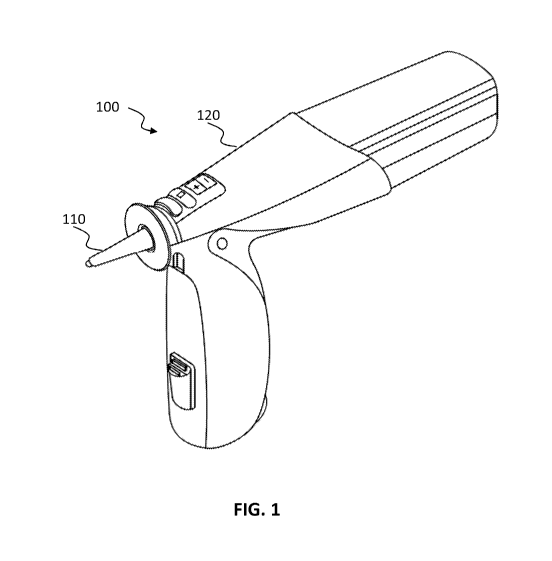
[0049] FIG. 1 is a diagram illustrating an example of a system 100 including a
three-
dimensional (3D) scanner having an inflatable membrane 110, in accordance with
some example
embodiments of the current subject matter. The system 100 and accompanying
software may
generate three-dimensional (3D) scans of a cavity, such as an ear cavity.
System 100 may include a
3D scanner 120 including inflatable membrane 110 and a processor, such as a
computer. The
processor may process scanner data generated by 3D scanner 120 during a scan
of the cavity. The
processor may form an output, such as a 3D impression of the scanned cavity.
[0050] FIG. 2 is a diagram illustrating an example 3D rendering of a cavity
formed based on
scanner data collected and processed by the 3D scanner 120, in accordance with
some example
embodiments. The 3D surface, also referred to herein as an electronic
representation 200, may
model the scanned cavity, such as an ear cavity, and this 3D surface may be
provided to a
manufacturer, 3D printer, and the like to form an object. In the case of the
ear, the object may be an
earpiece or earbud/earbud adapter.
-9-
CA 03000939 2018-04-03
WO 2017/062868 PCT/US2016/056132
[0051] As used herein, the terms "earbud," "earpiece," and "earbud adaptor"
can include
any sort of appliance that may be worn on the ear, in the ear, or any
combination thereof For
example, this may include earbuds for speakers, wireless transmitter/receivers
hooked over the ear,
earplugs, headphones, personal hearing protection, hearing aids, or the like.
[0052] More generally, the terms "earbud," "earpiece," and "earbud adaptor"
may also refer
to any appliance or object that may be manufactured to conform to any cavity
or internal space
scanned by any of the scanning techniques described herein. Many of the
implementations
described herein refer to scanning an ear as part of a process of
manufacturing an earbud. However,
these implementations do not exclude using any of the apparatus or techniques
described herein for
the manufacture of other objects, apparatuses, tools, or the like.
[0053] FIG. 3 is a diagram illustrating the 3D scanner 120 with a scanning tip
320 in an
extended position, in accordance with some example embodiments. FIG. 4 is a
diagram illustrating
the 3D scanner 120 with a scanning tip 320 in a retracted position, in
accordance with some
example embodiments. A medium 310 may be used to inflate and expand the
interior of the
inflatable membrane 110 so that the inflatable membrane 110 conforms an
external surface of the
inflatable membrane 110 to an interior shape of a cavity 330, or portion of
the cavity 330, or any
other cavity 330 or surface being scanned.
[0054] For example, the medium 310 may be inserted into the inflatable
membrane 110, so
that inflatable membrane 110 conforms to the cavity 330 being scanned. At this
point, scanning tip
320 may scan the interior surface of the inflatable membrane 110 which, when
inflated with the
medium 310, conforms an external surface of the inflatable membrane 110 to an
interior shape of
the cavity 330. The interior shape can be, for example, the interior shape of
an ear or other object.
The scanning tip 320, which may include a light emitter and detector, can
actuate between an
-10-
CA 03000939 2018-04-03
WO 2017/062868 PCT/US2016/056132
extended position and a retracted position during the generation and detection
of the light used for
scanning. In this way, scanning tip 320 may scan the interior surface of the
inflatable membrane
110 and thus cavity 330. The scanning tip 320 may generate a 2D image of the
inflatable
membrane approximating a snap shot of the cavity 330. Each pixel of the 2D
image may then be
associated with distance information obtained during a scan, for example, the
distance from the
scanning tip 320 to the scanned portion of the membrane. The combination of
the 2D image and
distance information for each pixel of the 2D image may correspond to 3D data
(for example, a 3D
surface representative of the scanned cavity 330). In some implementations,
the distance
information determined from scanning data can correlate to groups of pixels,
instead of a single
pixel, on the 2D image.
[0055] Medium 310 may, for example, be a liquid, a dissolved gas, a gel, a
hydrogel, and/or
any combination of the four. The medium 310 may include additives dissolved
into, or suspended
in, the medium 310 to provide properties. These properties may include, for
example, such as
selective absorption where one or more wavelengths of light are absorbed more
than one or more
other wavelengths. To illustrate, medium 310 may include a colored dye,
suspension, a luminescent
substance, and/or a fluorescent substance (and/or any other material having
selective attenuation
properties). The medium 310 may also contain a bio-neutralizing, anti-
microbial, or anti-oxidizing
agent to improve the shelf life of the medium 310 as well as a buffering agent
to improve the
stability of the medium 310. Moreover, the selective attenuation properties
may, as described
further below, allow 3D scanner 120 and/or processor to determine the shape
of, distance to, and/or
other properties of the scanned interior surface of inflatable membrane 110.
[0056] The inflatable membrane 110 may be implemented as any viscoelastic,
elastic,
plastic, and/or any other material that may be inflated to conform to the ear
cavity 330, when the
-11-
CA 03000939 2018-04-03
WO 2017/062868 PCT/US2016/056132
inflatable membrane 110 is inserted into the cavity 310 and inflated with
medium 310. When the
cavity 330 corresponds to an ear canal, inflatable membrane 110 may have an
inflated 3D shape and
size that is substantially adapted to the ear cavity 330. The inflatable
membrane 110 may be used
with other cavities and forms, for example, a stomach, an esophagus, a
bladder, and or the like. The
inflatable membrane 110 may also include, or be coated with, a material to
make the membrane
fluoresce light of a particular wavelength, or a range of wavelengths, as
further described below. In
some implementations, the inflatable membrane may have a balloon-like shape
with an opening, an
interior surface, and an exterior surface. In some implementations, scanning
the inflatable
membrane 110, rather than the ear cavity 330 directly, may reduce (if not
eliminate) the interference
caused by artifacts, such as ear hair, wax, and the like, and may thus improve
the accuracy of the
cavity measurement scan.
[0057] FIG. 5 is a diagram illustrating the attenuation of reflected light by
a medium 310 in
the inflatable membrane 110, in accordance with some example embodiments. The
3D scanner 120
and/or the scanning tip 320 may include at least one light source, such as a
light emitting diode, for
emitting light into the inflatable membrane 110, which may or may not include
medium 310. In
FIG. 5, the emitted light 510 is represented by the arrows going out from the
scanning tip 320. The
scanning tip 320 may also collect and/or detect light 520 and 530 that is
emitted from fluorescent
material in, or on, the inflatable membrane 110. The light 510 emanating from
scanning tip 320
may comprise light used to excite the fluorescent material in, or on, the
inflatable membrane 110.
Further, light from the fluorescent material in, or on, the inflatable
membrane 110 may be referred
to as "fluoresced" light, i.e., light resulting from the interaction of the
fluorescent material with the
light 510 from scanning tip 320.
-12-
CA 03000939 2018-04-03
WO 2017/062868 PCT/US2016/056132
[0058] The inflatable membrane 110 may include a fluorescent material, such as
one or
more fluorescent dyes, pigments, or other coloring agents. The fluorescent
material can be
homogenously dispersed within the inflatable membrane 110, although the
fluorescent material may
be applied in other ways as well (for example, the fluorescent material may be
pad printed onto the
surface of the inflatable membrane). The fluorescent material may be selected
so that the
fluorescent material is excited by one or more wavelengths of light 510
emitted by the scanning tip
320. Once the fluorescent material is excited by light 510, the fluorescent
material may emit light at
two or more wavelengths X1, X.2, or a range of wavelengths. For example,
wavelength Xi may
represent a range of wavelengths associated generally with red, although
wavelength Xi may be
associated with other parts of the spectrum as well.
[0059] In some implementations, the medium 310 may differentially attenuate,
for example
based on wavelength or other property, light passing through the medium 310.
For example, as the
two or more wavelengths of light 520 propagate through the medium 310 along
paths l and 12,
12, the medium 310 may absorb one or more of the wavelengths of light Xi, X2
to a greater degree
than one or more other wavelengths of the light. The medium 310 used in the
system 100 may also
be selected to optimally and preferentially absorb one or more of the
wavelengths or a range of
wavelengths of light from the fluorescent material of the inflatable membrane.
By selecting a
medium 310 that complements the fluorescent material, the scan data collected
by the 3D scanner
120 may be more accurate.
[0060] Similar to the process described with reference to FIG. 3, when the
scanning tip 320
of 3D scanner 120 is inserted into ear cavity 330, 3D scanner 120 may pump (or
insert in other
ways) medium 310 into inflatable membrane 110 until the inflatable membrane
110 conforms to the
interior surface of the cavity 330. Once the inflatable membrane 110 is fully
inflated, 3D scanner
-13-
CA 03000939 2018-04-03
WO 2017/062868 PCT/US2016/056132
120 and/or scanning tip 320 may emit light 510 with an emitter, for example a
light emitting diode.
Light 510 may travel from the scanning tip 320, through medium 310, and excite
the fluorescent
material on, or in, a portion of the inflatable membrane 110. The light 520,
530 emitted from the
fluorescent material on, or in, the inflatable membrane 110 may include at
least two wavelengths of
light, X1, and 21,2. One of the wavelengths of light or some ranges of
wavelengths of light emitted by
the fluorescent material may be differentially attenuated by the medium 310.
The differential
attenuation may be due to the medium 310 attenuating light at a first optical
wavelength Xi at first
rate per unit length
and attenuating light at a second optical wavelength X2 at a second rate per
unit length I-12. The attenuation can be described, for example, as
11(x) = /1(0)e-glx
(1)
for the attenuation of the intensity of light at wavelength Xi and
12(x) = (0)e -I12x.
(2)
[0061] Here, the initial intensity, for example at the point of emission from
the fluorescent
material, is I(0) or 12(0). As the light propagates through the medium 310 a
distance x along a path
between the point of emission and the scanning tip 320, the light may be
reduced in intensity or
attenuated by the medium 310. The attenuation may be due to, for example,
absorption, reflection,
scattering, diffraction, or the like.
[0062] The light having wavelengths X.1, X2 or wavelength ranges of light, may
then be
received by a detector. The detector may be integrated with the scanning tip
320 and may be
configured to receive light from the interior surface of the inflatable
membrane 110. The ratio of
the intensities of light X1, X2 or the ratio of the integral area of light
found under specific ranges may
be measured and recorded by 3D scanner 120 and/or processor to determine a
distance from the
scanning tip 320 to corresponding surface of the membrane 110. For example,
the distance x may
-14-
CA 03000939 2018-04-03
WO 2017/062868 PCT/US2016/056132
be determined by inverting Eqns. (1) and (2). The scanning tip 320 may move
throughout the
interior of inflatable membrane 110 to scan various portions of the interior
surface of the inflatable
membrane 110. The scanning tip 320 may receive the fluoresced wavelength of
light 520, 130 in
order to collect data that may be used by the 3D scanner 120 and/or processor
to generate an
electronic representation 200 of an interior shape of the ear to form a 3D
surface representative of
the cavity 330. Alternatively, or additionally, the scanning tip 320 may
include optical, electronic,
or mechanical components for focusing and directing the light used to excite
the fluorescent
material. Although the scanning tip 320 may include one or more components,
such as one or more
light emitting diodes, optics, lenses, detectors/CCDs/CMOS sensors, and the
like, one or more of
these components may be located in other portions of the 3D scanner 120 (for
example, an optical
fiber may carry light 510 to scanning tip 320).
[0063] In some example embodiments, the 3D scanner 120 in accordance with
FIGs. 1-5
may scan the deep ear canal. The inflatable membrane may also deform the
concha by inflating the
inflatable membrane 110 to a predefined pressure or until a predefined
deformation of the concha is
achieved.
[0064] FIG. 6 is a diagram illustrating membrane-less determination of the
distance to a
proximal location 610 of an inner surface 620 of the ear, in accordance with
some example
embodiments. FIG. 7 is a diagram illustrating membrane-less determination of
the distance to a
distant location 710 of an inner surface 620 of the ear, in accordance with
some example
embodiments. The light source may comprise a red LED providing red wavelength
light 630, and a
green LED providing green wavelength light 640. Any differing wavelength of
light may be used.
The light source may emit light that reflects from the actual tissue of the
interior surface of the ear
(i.e. no inflatable membrane 110). Similar to that described above, because
the absorbing medium
-15-
CA 03000939 2018-04-03
WO 2017/062868 PCT/US2016/056132
may absorb, for example, red and green light differently, the reflected red
and green light from
portion C 610 may be received, detected, and represented as a ratio of
intensities, such as detected
red wavelength intensity over the detected green wavelength intensity.
Meanwhile, as shown in
FIG. 7 the reflected red and green light from portion D 710 may be received,
detected, and
represented as a ratio of intensities as well. Given that the distance from
portion D 710 to the distal
portion of the scanning tip 320 (where the light receiver is located) is
greater than the corresponding
distance between portion C 610 and receiver, the medium 310 has a greater
attenuating effect on the
reflected light from portion D 710 as shown by the inset graphs. However,
secondary reflections
may be a source of noise for the measurement. In some embodiments, the
selection of wavelengths
used can reduce this noise.
[0065] FIG. 8 is a diagram illustrating an exemplary reflectance spectra 810
of a portion of
an ear, in accordance with some example embodiments. In some embodiments,
selection of the two
different wavelengths of light may be chosen such that their reflectance from
the interior surface of
the ear is low. For example, when the reflectance of the tissue is low, then
each subsequent
reflection reduces the intensity by a factor of 1/R, where R is the
reflectance. Combined with the
absorbing properties of the medium 310, this preferentially attenuate the
light received at the
detector that was not due to the primary reflection from the point whose
distance from the detector
is being determined. FIG. 8 shows, for example, that the a first wavelength
may be selected, for
example corresponding to green light within band 820 and a second wavelength
may be selected,
for example corresponding to red within band 830, so that these bands 810 and
820 are located
where the reflectance due to the tissue on the surface of the cavity 330 is at
a first minima 830 or at
a reduced reflectance 840 relative to another portion of the spectra. In the
example of FIG. 8, the
reflectance from the tissue on the surface of the cavity 330 also contains a
maxima 850, so the
-16-
CA 03000939 2018-04-03
WO 2017/062868 PCT/US2016/056132
reflectance from the tissue at this wavelength may contribute to noise or
interference at the detector.
In some example embodiments, the scanning tip 320 may include a green light
source in the range
of 475-505 nanometers and a red light source in the range of 655-700
nanometers.
[0066] Although some of the examples described herein refer to using two
wavelengths at
red and green, other wavelengths may be used as well. For example, the
intensity of other
wavelengths of light can be detected at the scanning tip 320 and then measured
and compared may
include an combination of the following: violet light (approximately 380 to
450 nm), blue light
(approximately 450 to 495 nm), green light (approximately 495 to 570 nm),
yellow light
(approximately 570 to 590 nm), orange light (approximately 590 to 620 nm),
and/or red light (620-
750 nm).
[0067] FIG. 9 is a diagram illustrating a serial linkage between a structured
light source 910
and camera 920, in accordance with some example embodiments. When making
multiple scans
with the same scanner or different types of scanners, the scanners can be
rigidly coupled, made
integral, or otherwise mechanically joined so that the relative position of
each scanner is known
when combining the resultant scan images.
[0068] The 3D scanner 120 such as the scanner disclosed in FIGs. 1-5 may be
used to scan
the deep ear canal. A structured light source / camera assembly 940
integrating the structured light
source 910 and camera 920 is also depicted in FIG. 9. A mechanical linkage
between the structured
light source / camera assembly 940 and the 3D scanner 120 may provide more
accurate position
information for the scan data. For example, a serial linkage may be used
between the structured
light source /camera assembly 940 and the 3D scanner 120. The serial linkage
may include
mechanically coupling the 3D scanner 120 to the structured light source /
camera assembly 940
where both may also mechanically coupled to a robotic arm 950 or other gantry.
The robotic arm
-17-
CA 03000939 2018-04-03
WO 2017/062868 PCT/US2016/056132
950 may be configured to monitor the position and orientation of the coupled
3D scanner 120 and
structured light source / camera assembly 161. For example, the 3D scanner 120
may be used to
scan a portion of the ear. Then, the structured light source /camera assembly
940 may be translated
by the arm into position to scan the same (or different) portion of the ear.
Combining the data on
the positions of each type of scanner when the scan was made may allow the
spatial data or
generated 3D surfaces for the two scans to be synchronized for combination to
form a composite
scan.
[0069] In some example embodiments, the concha region may be scanned using a
structured
light source 920 and a camera 910 without deforming the concha. Methods
described herein that do
not rely on physical contact between the scanning implement and the surface
being scanned can
avoid the creation of artifact or other distortions in the measurements of the
scanned surface. In
some example embodiments, a scan of the ear canal including the deep ear canal
and the concha
may include two scans; one with the 3D scanner 120 and another scan performed
using structured
light and/or direct imaging by a camera. The two scans can be aligned and
merged using common
locations at or near the aperture of the ear canal and interpolate/smooth the
transition between the
two surfaces in the scans. For example, the two scans may be merged by a
design computer to
produce a combined scan or model of two or more scanned surfaces or shapes. In
some
implementations, the camera 920, detector, or other imaging receiver may
include a stereoscopic
camera or optical system. A stereoscopic camera may enable 3D images to be
acquired without
having to use structured light or an inflatable membrane 110. However, some
implementations can
combine the stereoscopic camera with any of the other imaging techniques
described herein.
[0070] FIG. 10 is a diagram illustrating imaging a 3D object 1010 with a
structured light
source 910 and camera 920, in accordance with some example embodiments. A
camera 920 may
-18-
CA 03000939 2018-04-03
WO 2017/062868 PCT/US2016/056132
image an object illuminated by structured light source 910. Geometric details
of the illuminated
object can be determined from the image as shown by the example of a
hemisphere 1020. A
structured light source may include illumination that is patterned or includes
some form of spatial
variations in intensity, wavelength, frequency, phase, or other properties of
the light. By generating
a predictable and predefined pattern of light on the surface to be scanned,
the images of the pattern
can be analyzed to determine distance or other surface features. For example,
a structured light
source may include a series of alternating light and dark bars, although other
patterns may also be
used. In some example embodiments, features of a three-dimensional object may
be determined
from the projection of the structured light onto the object. In one example,
the projection onto the
hemisphere 1020 of the alternating bars of light and dark causes the bars to
appear wider due to the
hemispherical shape when viewed from the side. FIG. 1030 also illustrates an
example of an image
showing a structured light pattern on the surface of a person. The structured
light pattern generated
inside the ear may be similar to the appearance of the structure light pattern
on the person.
[0071] In some embodiments, the camera 920, or other detector, can detect
structured light
generated from a pattern imprinted on an interior surface of the inflatable
membrane 110. For
example, dots, lines, grids, or other visual patterns can be present on the
inflatable membrane 110
prior to scanning. The pattern may be illuminated to generate structured light
from the interior
surface. In other embodiments, the emitter can emit structured light to form a
pattern on the interior
surface of the inflatable membrane 110 conforming to an interior shape of an
ear and detecting the
structured light generated by reflection from the interior surface. These may
be done without using
the medium 320 by, for example, inflating the inflatable membrane 110 with air
or other uniformly
attenuating material. Once the light is detected, the light can be analyzed as
described herein to
identify the shape of the scanned surface.
-19-
CA 03000939 2018-04-03
WO 2017/062868 PCT/US2016/056132
[0072] FIG. 11 is a process flow diagram illustrating combining a scan from a
3D scanner
120 and another scan from a structured light source and camera, in accordance
with some example
embodiments. At 1110, a first scan of an ear may be taken using a 3D scanner
120 such as the
scanner described in FIGs. 1-5. At 1120, the scan may be adjusted and/or
processed to determine a
shape of the ear canal. At 1130, another scan of the ear may be taken using a
different type of
scanner. For example, the structured light / camera assembly 940 may be used
to generate a second
scan. At 1140, the second scan may be adjusted and/or processed to determine a
shape of the
concha. In some example embodiments, the first scan and the second scan may be
performed
together at the same time. In some example embodiments, one scanner may
perform both scans.
For example, a 3D scanner 120 and a structured light source / camera assembly
940 may be
combined into a single scanner. At 1150, the scan from the 3D scanner 120 and
the scan from the
structured light source / camera assembly 940 may be aligned with one another.
For example, the
position of first scan relative to the second scan may be adjusted so that a
region of the ear captured
by both scans may be used to align the two scans. After alignment, at 1160,
the two scans may be
merged.
[0073] In some example embodiments, the scans may be merged where the
overlapping
portions of the scans correspond to a transition region from one scan to the
other scan. In some
example embodiments, the scans in the transition region may be averaged with
the scans being
assigned equal weighting, or different weightings to preferentially bias the
composite scan towards
one scanning technique. For example, some methods described herein involve
contact between the
surface of the ear being scanned and any foreign object, such as the
inflatable membrane 110.
Because methods involving contact can cause mechanical deformation of the
surface, this can
introduce an error in measurement. When combining scans, methods that do not
involve contact
-20-
CA 03000939 2018-04-03
WO 2017/062868 PCT/US2016/056132
(such as membrane-less scans using a structured light source) may be biased to
have greater weight
than scans that did involve contact. The weighting may be on a pixel-by-pixel
basis, such as based
on a measurement or estimate of the amount of deformation of the ear surface,
or can be constant
over all pixels for the given scan type.
The weighting may be applied to any
interpolation/smoothing algorithms or be indicated graphically to a user
manually merging the scans
with modelling software.
[0074] In other embodiments, when the scans do not overlap, interpolation
between the
scans may be used to combine the scans. In another embodiment, one or more
scans can be
extrapolated to extend the effective scan surface. In other embodiments, the
scans may be
combined with input from an operator visually aligning the individual scans
rendered on a
computing device.
[0075] In other example embodiments, based on the electronic representation
200 or scans
from either or both of the 3D scanner 120 and a structured light source /
camera assembly 940,
native references in the ear can be identified. Native references can be
specific portions of the ear
anatomy, for example, a concha, eardrum, or the like. Native references can
also be specific
contours of any portions of the ear anatomy. The native references may be
referenced by the
processor to facilitate combining scans by providing common points of
reference. In some
embodiments, this can be used with the structured light source / camera
assembly 940 generating
electronic representations of the ear where, due to the method not requiring
the inflatable membrane
110, no deformation of the interior surface of the ear is performed.
[0076] FIG. 12 is a diagram illustrating an example transition region between
example
scans from a 3D scanner 120 and a structured light source 930 and camera 920,
in accordance with
some example embodiments. Depicted at 1210 are example scans for the right and
left ear canals
-21-
CA 03000939 2018-04-03
WO 2017/062868 PCT/US2016/056132
from a conformal membrane scanner (also referred to herein as a 3D scanner
120) such as a scanner
consistent with FIGs. 1-5. Depicted at 1220 are example scans for the right
and left ears from
another scanner such as a structured light source / camera assembly 940
disclosed in FIGs. 9-10.
Depicted at 1230 are transition regions for the right and left ears. The
transition regions may
correspond to areas where the scan from the 3D scanner 120 and the scan using
the structured light
source 930 and camera 920 overlap. In some example embodiments, the transition
regions 1230
may be determined using interpolation, or averaging, or other analytical
method of merging the two
scans. In some example embodiments, the transition regions 1230 may be
adjusted by an operator.
In regions where no scan was available, and interpolated, extrapolated, or
otherwise synthetic data
was used to merge actual scan surfaces, an indication of the transition region
1230 may be indicated
with different colors, patterns, or other visual indicators.
In other implementations, a second scanner, or a second scan from the 3D
scanner 120, may
generate a second electronic representation of a second shape. The second
shape may include a
second interior shape of a portion of the cavity, a second portion of a second
surface proximate to
the cavity, or the like. The second interior shape can be another part of an
ear or any other portion
of the cavity 310. Similarly, the second portion of the second surface can be
part of an area outside
the cavity, such as the concha of an ear or other nearby external structural
feature of the object
being scanned. The second scanner can be, for example, the 3D scanner 120, a
structured light
source 910 and camera 920, or a laser rangefinder.
[0077] FIG. 13 is a diagram illustrating examples of earbud adapters 1300, in
accordance
with some example embodiments. The earbud adapter 1300 may have an adapting
portion 1310 to
fit a commercial earbud or other earbud. Earbud adapter 1300 may have a
customized portion 1320
custom-produced to fit a particular person's ear based on the scan. The
customized portion 1320
-22-
CA 03000939 2018-04-03
WO 2017/062868 PCT/US2016/056132
may comprise a soft and/or flexible material. The adapting portion 1310 may
comprise the same
material or a different material. A right/left earbud adapter 1330 is shown
coupled to a commercial
earbud. A left/right earbud adapter 1340 is shown coupled to a commercial
earbud is shown. The
right and/or left earbuds may be colored so to distinguish the right and left
earbuds/earbud adapters.
[0078] In accordance with some example embodiments, an earbud adapter 1300 may
be
made from a flexible material such as silicone. The earbud adapter 1300 may be
produced from a
scan performed on the ear canal to measure the size and shape of the ear
canal. In some example
embodiments, the scan may also determine the shape of the concha and/or other
external ear shape.
The earbud adapter 1300 may be made to fit the measured shape. The measured
shape may be
adjusted to reduce the length of the earbud in the ear canal, adjust the shape
of the earbud on the
surface outside the ear, and/or to change the shape to adapt the earbud to a
standard earbud, or any
other commercial earbud.
[0079] The fabrication process for earbuds or in-ear headphones may include
adding
speakers that may be wired devices or may be wireless devices. The additional
components, for
example, the speakers or wires, can be added by a second apparatus such as an
automated
manufacturing device. A wireless earbud may receive a signal transmitted from
a cellular phone,
music player or other electronic device. The sound generating devices may
generate sound such as
music or voice or may provide passive noise reduction and/or active noise
cancellation. Passive
noise reduction may occur due to the custom size and fit of the custom
earbuds/earbud adapters
and/or by a choice of the earbud material. For example, some earbud materials
may provide more
sound attenuation through the earbud than other materials. Active noise
cancellation may include
causing the sound generating devices in the earbuds to cancel noise that
passes through or around
the earbud at the ear canal side of the earbud. In this way, noise may be
reduced at the ear canal. In
-23-
CA 03000939 2018-04-03
WO 2017/062868 PCT/US2016/056132
some example embodiments, active noise cancellation may be performed in
addition to sound
generation of music or voice that the user has selected. For example, active
noise cancellation and
sound generation may be used to cancel aircraft noise and provide the user
with music or voice
during a flight.
[0080] Other additional components that may be included as part of the earbuds
may
include, for example, microphones, transmitters, receivers, padding,
additional conformal adaptors
to increase comfort or fit to the cavity 330, or the like. Also, the
additional components can include
biometric scanners, sensors, computer processors, electronic components for
connected devices, or
the like.
[0081] FIG. 14 is a process flow diagram illustrating a first process, in
accordance with
some example embodiments.
[0082] At 1410, the ear canal may be scanned by a scanner consistent with
FIGs. 1-5. In
some example embodiments, a second scanner consistent with FIGs. 9-10 may be
used to scan the
concha or other outer region of the ear. After the first ear is scanned, the
second ear may be
scanned. In some example embodiments, the shape of the ear canal and/or concha
may be provided
electronically as a 3D model or array of 2D models of the ear. In some example
embodiments, the
shape of the ear canal and./or concha may be determined from another source
such as a magnetic
resonance imaging or other imaging. In some example embodiments, the shape
and/or model of the
ear may be included in an electronic medical record.
[0083] At 1420, an earbud design may be produced based on the scan. In some
example
embodiments, the earbud design may include the scan after one or more
adjustments. For example,
the length of the earbud in the ear canal may be adjusted to be longer or
shorter than the scanned ear
canal. In some example embodiments, the length or external shape at the
exterior of the ear may be
-24-
CA 03000939 2018-04-03
WO 2017/062868 PCT/US2016/056132
adjusted. For example, the earbud may be adjusted in length to protrude more
or less from the ear
canal. In some example embodiments, the adjustments may include adjustments to
cause improved
attachment to the ear so that the earbud is less likely to fall out during
use. In some example
embodiments, the adjustments may include an opening at the exterior of the
earbud to adapt and
hold into place a standard earbud and/or other earbud.
[0084] At 1430, the earbud design may be produced on a fabrication machine.
For example,
the earbud design may be produced on a three-dimensional (3D) printer. In some
example
embodiments, a 3D printer may fabricate a 3D mechanical structure using one or
more selectable
materials. For example, a 3D printer may produce layers of material with
selectable regions of the
different materials. 3D printers may deposit regions of material that include
polyamide, urethane,
plastic, ceramic, metal, paper, wax, or other material. In some example
embodiments, the earbud
design may be produced on a 3D printer with the exterior regions of the earbud
made using a shell
of rigid material such as polyamide, urethane or other material and with the
interior volume made
from another material such as wax. The polyamide or urethane shell can be
formed to a
predetermined thickness, for example, between 0.05 mm and 2 mm. In some
example
embodiments, the removable material may have a lower melting point than the
rigid material, or
may be soluble in a solvent in which the rigid material is not soluble. The
rigid exterior region may
be referred to as an earbud shell. In some example embodiments, the wax from
the interior of the
earbud shell may be removed by heating the earbud shell and allowing the wax
to drain out. For
example, the wax may drain out when the shell is heated due to gravity or
draining may be assisted
by applying air pressure or placing the shell in a centrifuge. In some example
embodiments, after
the interior material such as wax has been removed, the earbud shell may be
filled with a flexible
material such as curable silicone or other material. After the silicone has
cured in the shape of the
-25-
CA 03000939 2018-04-03
WO 2017/062868 PCT/US2016/056132
interior of the earbud shell, the shell may be removed leaving the flexible
earbud. The silicone or
other flexible material may have a hardness of approximately 15-75 shore or
other hardness. In
some example embodiments, the earbud shells may be produced without a parting
line for use one
time. Earbud shells produced with a parting line may be used multiple times to
make multiple
earbuds. In some example embodiments, digital light processing (DLP) may be
used instead of or in
addition to 3D printing. In some example embodiments, DLP may include exposing
light to liquid
resin to produce a desired shape. In some example embodiments, DLP may result
in solid objects
without a shell and without the interior wax to remove.
[0085] At 1440, finishing steps may be performed on the flexible earbud. In
some example
embodiments, the earbud may be marked or color-coded so that earbuds may be
easily identified
and which earbud is for the right ear and which earbud is for the left ear. In
some example
embodiments, the earbud may be smoothed, marked, rinsed, cleaned, and/or
prepared for use.
[0086] FIG. 15 is a process flow diagram illustrating a second process, in
accordance with
some example embodiments.
[0087] At 1505, an ear may be scanned to determine the internal and/or
external shape of
the scanned ear. In some example embodiments, the scanning may be performed
using an optical
scanner such as the scanner described with respect to FIGs. 1-5. In some
example embodiments, the
scan may be performed using a different type of scanner such as a photographic
scanner, magnetic
resonance imaging, dye enhanced, or other scanner. In some example
embodiments, the shape of
the ear may be provided electronically as a 3D model or an array of 2D models
or images. The
shape/model may be part of an electronic medical record.
[0088] At 1510, the scan may be adjusted to change the length and/or
accommodate an
earbud. In some example embodiments, the earbud design may include the scan
after one or more
-26-
CA 03000939 2018-04-03
WO 2017/062868 PCT/US2016/056132
adjustments. In some example embodiments, the scan, or a mathematical or
electronic model of the
scan, may be adjusted using a design computer that may run 3D design/modelling
software,
Computer-Aided Drafting/Drawing (CAD) software, or the like. The design
computer can be
configured to modify one or more electronic representations into a three-
dimensional shape
corresponding to at least a portion of the interior shape of the ear. For
example, the length of the
earbud in the ear canal may be adjusted to be shorter than the scanned ear
canal. In some example
embodiments, the length or external shape of the earbud at the exterior of the
ear may be adjusted.
For example, the earbud may be adjusted in length to protrude more or less
from the ear canal. In
some example embodiments, the adjustments may include adjustments to cause
improved
attachment to the ear so that the earbud is less likely to fall out during
use. In some example
embodiments, the adjustments may include an opening at the exterior of the
earbud to adapt and
hold into place a standard earbud and/or other earbud.
[0089] At 1515, a shell or earbud may be produced on a fabrication machine
from the
modified electronic representation or scan. In some example embodiments, a 3D
printer or digital
light processing system may be used to produce earbud shells. For example, a
3D printer may
"print" or deposit successive layers of material to produce a 3D object. For
example, a 3D printer
may deposit two materials in successive layers such as a hard or rigid
material on outside surfaces
to produce a shell, and another material that is removable in the interior
such as wax that aids in
supporting the shell as the layers are deposited. In some example embodiments,
the removable
material may have a lower melting point than the rigid material, or may be
soluble in a solvent in
which the rigid material is not soluble. The 3D printer may be controlled by a
computer to produce
earbud shells in accordance with the scanned ear or the adjusted scan of the
ear. In some example
-27-
CA 03000939 2018-04-03
WO 2017/062868 PCT/US2016/056132
embodiments, extrusion and sintering-based processes may be used. The 3D
printed shells may be
produced by the 3D printer on a plate. The shells may then be cleaned or
rinsed.
[0090] At 1520, the shell may be cured. For example, the shell may be cured
over a time
period with or without being heated in an oven.
[0091] At 1525, the shell may be released. For example, the earbuds may be
released from
a plate associated with the 3D printer.
[0092] At 1530, the shell may be cleaned and the inner wax material may be
melted and
drained out of the shells. For example, the wax in the shells may be melted in
the oven at a
temperature such as 70 degrees Celsius or another temperature for 45 minutes
or another amount of
time. The earbud shells with the internal wax removed may be cleaned using a
solution such as
mineral oil, at a particular temperature for a particular amount of time. For
example, the earbud
shells may be cleaned with mineral oil at 70 degrees Celsius for 15 minutes.
The shells may be
further cleaned and/or rinsed with a second liquid such as water. The shells
may be dried using
compressed air and/or placing the shells in an oven at, for example, 70
degrees Celsius.
[0093] At 1535, the shell may be filled with a flexible material. For example,
the earbud
shells may be filled by injecting silicone or another flexible material into
the shells. The injected
compound may be liquid before curing and solid after curing.
[0094] At 1540, the material in the shell may be cured to form the earbud. In
some example
embodiments, the material in the shell may include silicone. Pressure may be
applied to the filled
earbud shells by, for example, a pressure pot. For example, the pressure pot
may be held at a
pressure of 6 bars at a temperature of 85 degrees Celsius for 10 minutes.
After the material such as
silicone in the shells has cured, the shells may be removed. In some example
embodiments, shells
made without a parting line may be removed by cracking them with an arbor
press. In some
-28-
CA 03000939 2018-04-03
WO 2017/062868 PCT/US2016/056132
example embodiments, shells made with a parting line may not require cracking.
In some example
embodiments, a shell post may be removed in a central portion of the earbud.
In some example
embodiments, a grinder may be used to finish the earbud to ensure smoothness
and remove any
excess material remaining from the silicone injection process. In some example
embodiments, the
left and right earbuds may be marked in order to tell them apart. For example,
the right and left
earbuds may be marked with dyed silicone. For example, a small hole may be
made in each earbud
and colored silicone added. Additional curing, cleaning, rinsing, and drying
may be performed. In
some example embodiments, the earbuds may be lacquered. A centrifuge may be
used to ensure the
lacquer coating is thin. For example, the lacquered earbuds may be placed in a
centrifuge at 500
RPM a few seconds. In some example embodiments, the lacquered earbuds may be
dried under
pressure at 85 degrees Celsius for 5 minutes.
[0095] At 1545, the earbud may be marked with an identifier. For example, each
earbud
may be marked with an identifier to ensure that the correct earbud is sent to
a user. The right and
left earbuds may be marked using different colors so that the user can
visually distinguish the right
earbud from the left earbud.
[0096] At 1550, the earbud may be shipped to a user.
[0097] Though the methods, apparatus, and systems are described herein with
respect to an
earpiece and scanning an ear canal, these methods, apparatus, and systems may
be applied to any
cavity 330 or orifice assembly for scanning any suitable anatomical cavity
330. For example, the
methods, apparatus, and systems can be used for scanning oral, nasal, renal,
intestinal, or other
anatomical cavities, and can involve assemblies designed for those anatomical
cavities. Further,
these methods, apparatus, and systems may be used with sensitive or fragile
cavities that are not
anatomical in nature, such as those made from brittle, pliable, or otherwise
delicate materials.
-29-
CA 03000939 2018-04-03
WO 2017/062868 PCT/US2016/056132
[0098] Without in any way limiting the scope, interpretation, or application
of the claims
appearing below, a technical effect of one or more of the example embodiments
disclosed herein is
reusability of certain components. Moreover, without in any way limiting the
scope, interpretation,
or application of the claims appearing below, a technical effect of one or
more of the example
embodiments disclosed herein is that the medium providing assembly may be used
for multiple
scans, including for multiple patients. In some implementations, the absorbing
medium and medium
providing assembly may be used for 10-15 scans or more. Furthermore, without
in any way
limiting the scope, interpretation, or application of the claims appearing
below, a technical effect of
one or more of the example embodiments disclosed herein is that the absorbing
medium, and the
system as a whole, may be more likely to be shelf-stable, as it can be shipped
without contacting the
inflatable membrane until just before scanning.
[0099] FIG. 16 is a process flow diagram illustrating a third process, in
accordance with
some example embodiments.
[00100] At 1610, the 3D scanner 120 may scan an interior shape of a
cavity 330. The
scanning may include inflating an inflatable membrane with a medium 310 to
conform an exterior
surface of the inflatable membrane 110 to an interior shape of a cavity 330.
For example, the 3D
scanner 120 can be coupled to the inflatable membrane 110 as shown in FIG. 1.
[00101] At 1620, light can be generated from an emitter to
illuminate the interior
surface of the inflatable membrane 110. For example, the light may illuminate
fluorescent portions
of the inflatable membrane 110, illuminate a pattern imprinted on the
inflatable membrane 110,
create a structured light pattern on the inside of the inflatable membrane
110, or the like.
[00102] At 1630, a detector may detect light emitted from the
interior surface of the
inflatable membrane 110. For example, the light may include a first optical
wavelength and a
-30-
CA 03000939 2018-04-03
WO 2017/062868 PCT/US2016/056132
second optical wavelength. The first optical wavelength and the second optical
wavelength may be
generated by differential attenuation of fluorescing light from the inflatable
membrane, reflection of
light from the inflatable membrane where the light was first generated by a
multiple-wavelength
emitter, reflection of light from a pattern on the inflatable membrane, or the
like.
[00103] At 1640, a processor may generate a first electronic
representation 200 of the
interior shape based at least on the detected light. For example, the first
electronic representation
200 may be a 3D rendering generated by computer software and processor that
combines one or
more surfaces imaged by the 3D scanner 120. The first electronic
representation 200 may be
combined by interpolating or otherwise digitally expanding/merging image
portions, acquired by
the 3D scanner 120 or other scanning technique, into a composite image of the
ear.
[00104] At 1650, a second shape proximate to the cavity 330 may be
scanned to
generate a second electronic representation of the second shape. For example,
the second shape
may correspond to an outer part of the object scanned, or be another scan that
overlaps some or all
of the interior shape scanned with the 3D scanner or other scanning device.
[00105] At 1660, the design computer may modify the first electronic
representation
into a three-dimensional shape corresponding to at least a portion of the
interior shape. For
example, the modification may include digital deformation of the first
electronic representation,
rotation, translation, or other adjustment performed in software automatically
or by a user.
[00106] At 1670, the design computer may generate a combined
electronic
representation from the first electronic representation and the second
electronic representation. For
example, the combined electronic representation may include interpolating,
extrapolating, or
otherwise connecting features of the first electronic representation and the
second electronic
representation.
-31-
CA 03000939 2018-04-03
WO 2017/062868 PCT/US2016/056132
[00107]
At 1680, the fabricator may fabricate an earbud according to the combined
electronic representation. The fabrication process may include translating the
combined electronic
representation to instructions that for operation of a 3D printer or other
fabrication machine. The
fabrication process can also include forming a mold based on the combined
electronic
representation.
[00108]
One or more aspects or features of the subject matter described herein can be
realized in digital electronic circuitry, integrated circuitry, specially
designed application specific
integrated circuits (ASICs), field programmable gate arrays (FPGAs) computer
hardware, firmware,
software, and/or combinations thereof
These various aspects or features can include
implementation in one or more computer programs that are executable and/or
interpretable on a
programmable system including at least one programmable processor, which can
be special or
general purpose, coupled to receive data and instructions from, and to
transmit data and instructions
to, a storage system, at least one input device, and at least one output
device. The programmable
system or computing system may include clients and servers. A client and
server are generally
remote from each other and typically interact through a communication network.
The relationship
of client and server arises by virtue of computer programs running on the
respective computers and
having a client-server relationship to each other.
[00109]
These computer programs, which can also be referred to programs, software,
software applications, applications, components, or code, include machine
instructions for a
programmable processor, and can be implemented in a high-level procedural
language, an object-
oriented programming language, a functional programming language, a logical
programming
language, and/or in assembly/machine language. As used herein, the term
"machine-readable
medium" refers to any computer program product, apparatus and/or device, such
as for example
-32-
CA 03000939 2018-04-03
WO 2017/062868 PCT/US2016/056132
magnetic discs, optical disks, memory, and Programmable Logic Devices (PLDs),
used to provide
machine instructions and/or data to a programmable processor, including a
machine-readable
medium that receives machine instructions as a machine-readable signal. The
term "machine-
readable signal" refers to any signal used to provide machine instructions
and/or data to a
programmable processor. The machine-readable medium can store such machine
instructions non-
transitorily, such as for example as would a non-transient solid-state memory
or a magnetic hard
drive or any equivalent storage medium. The machine-readable medium can
alternatively or
additionally store such machine instructions in a transient manner, such as
for example as would a
processor cache or other random access memory associated with one or more
physical processor
cores.
[00110] To provide for interaction with a user, one or more aspects
or features of the
subject matter described herein can be implemented on a computer having a
display device, such as
for example a cathode ray tube (CRT) or a liquid crystal display (LCD) or a
light emitting diode
(LED) monitor for displaying information to the user and a keyboard and a
pointing device, such as
for example a mouse or a trackball, by which the user may provide input to the
computer. Other
kinds of devices can be used to provide for interaction with a user as well.
For example, feedback
provided to the user can be any form of sensory feedback, such as for example
visual feedback,
auditory feedback, or tactile feedback; and input from the user may be
received in any form,
including, but not limited to, acoustic, speech, or tactile input. Other
possible input devices include,
but are not limited to, touch screens or other touch-sensitive devices such as
single or multi-point
resistive or capacitive trackpads, voice recognition hardware and software,
optical scanners, optical
pointers, digital image capture devices and associated interpretation
software, and the like.
-33-
CA 03000939 2018-04-03
WO 2017/062868 PCT/US2016/056132
0 1 1 1] In the descriptions above and in the claims, phrases such as
"at least one of'
or "one or more of' may occur followed by a conjunctive list of elements or
features. The term
"and/or" may also occur in a list of two or more elements or features. Unless
otherwise implicitly
or explicitly contradicted by the context in which it used, such a phrase is
intended to mean any of
the listed elements or features individually or any of the recited elements or
features in combination
with any of the other recited elements or features. For example, the phrases
"at least one of A and
B;" "one or more of A and B;" and "A and/or B" are each intended to mean "A
alone, B alone, or A
and B together." A similar interpretation is also intended for lists including
three or more items.
For example, the phrases "at least one of A, B, and C;" "one or more of A, B,
and C;" and "A, B,
and/or C" are each intended to mean "A alone, B alone, C alone, A and B
together, A and C
together, B and C together, or A and B and C together." Use of the term "based
on," above and in
the claims is intended to mean, "based at least in part on," such that an
unrecited feature or element
is also permissible.
[00112] The subject matter described herein can be embodied in
systems, apparatus,
methods, and/or articles depending on the desired configuration. The
implementations set forth in
the foregoing description do not represent all implementations consistent with
the subject matter
described herein. Instead, they are merely some examples consistent with
aspects related to the
described subject matter. Although a few variations have been described in
detail above, other
modifications or additions are possible. In particular, further features
and/or variations can be
provided in addition to those set forth herein. For example, the
implementations described above
can be directed to various combinations and subcombinations of the disclosed
features and/or
combinations and subcombinations of several further features disclosed above.
In addition, the
logic flows depicted in the accompanying figures and/or described herein do
not necessarily require
-34-
CA 03000939 2018-04-03
WO 2017/062868 PCT/US2016/056132
the particular order shown, or sequential order, to achieve desirable results.
Other implementations
may be within the scope of the following claims.
-35-