Note: Descriptions are shown in the official language in which they were submitted.
CA 03000964 2018-04-04
WO 2017/062337
PCT/US2016/055272
HEAD AND NECK COMPRESSION THERAPY SYSTEM
[0001] CROSS-REFERENCE TO RELATED APPLICATIONS
[0002] This application claims the benefit of U.S. Provisional Application
No.
62/237,192, filed October 5, 2015, and entitled "Head and Neck Compression
Therapy
System"; U.S. Provisional Application No. 62/237,200, filed October 5, 2015,
and
entitled "Static and Dynamic Compression Therapy System"; and U.S. Provisional
Application No. 62/237,209, filed October 5, 2015, and entitled "Head and Neck
Compression Garment," all of which are incorporated herein in their entirety.
[0003] FIELD OF THE DISCLOSURE
[0004] The present disclosure relates generally to the use of compression
garments and
compression garment systems and to methods for applying pressure to a portion
of the
body (e.g., a portion of a head and a neck of a body).
[0005] BACKGROUND
[0006] Various types of compression garments are available, for example,
such as for
treatment of lymphedema, edema, wound healing, etc. For example, garments may
include inflatable cells (or other actuatable elements) to provide therapy to
patients and
may be positioned about any body portion of a person or animal. Specifically,
the
garments may be positioned about body portions that exhibit swelling due to a
build-up
of lymph and that would benefit from compression therapy provided by the
garments.
For example, such cells may be inflatable to one or more different pressures
in a variety
of sequences to provide the therapy to the patient by moving lymph from one
region to
another. In other words, such compression garments may be placed around at
least a
portion of an individual's body for use in applying pressure to the body at an
affected
extremity. These compression garments may be donned (e.g., put on) and doffed
(e.g.,
taken off) by patients themselves or with help from others.
- 1 -
CA 03000964 2018-04-04
WO 2017/062337
PCT/US2016/055272
[0007] SUMMARY
[0008] An exemplary compression garment system described herein may
include a head
garment portion configured to be donned on a head of a body, a neck garment
portion
configured to be donned on a neck of the body, and a controller. The head
garment
portion may include one or more head pressure applying regions and each of the
one or
more head pressure applying regions may be controllable to apply pressure to a
portion
of the head. The neck garment portion may include one or more neck pressure
applying regions and each of the one or more neck pressure applying regions
may be
controllable to apply pressure to a portion of the neck. The controller may be
configured to control pressure applied by each of the one or more head
pressure
applying regions and each of the one or more neck pressure applying regions to
move
lymph at least from the head towards the neck.
[0009] In one or more embodiments, the one or more neck pressure applying
regions may
be controllable to apply pressure to the portion of the neck after the one or
more head
pressure applying regions are controlled to apply pressure to the portion of
the head. In
one or more embodiments, the one or more neck pressure applying regions may be
controllable to apply pressure to the portion of the neck and the one or more
head
pressure applying regions may be controllable to apply pressure to the portion
of the
head to move lymph at least from the head towards the neck and downward
therefrom.
In one or more embodiments, the neck garment portion may define an open region
proximate an anterior portion of the neck of the body adjacent the trachea.
[0010] In one or more embodiments, the neck garment portion may include a
first neck
garment portion positionable proximate a right portion of the neck of the body
and a
second neck garment portion positionable proximate a left portion of the neck
of the
body. The first neck garment portion may include pressure applying regions
separate
from pressure applying regions of the second neck garment portion. In some
embodiments, the controller may be configured to control pressure applied by
the first
and second neck garment portions alternately (e.g., pressure is applied to the
first and
second neck garment portions alternately). In other embodiments, the
controller may
be configured to control pressure applied by the first and second neck garment
portions
simultaneously (e.g., pressure is applied to the first and second neck garment
portions
- 2 -
CA 03000964 2018-04-04
WO 2017/062337
PCT/US2016/055272
simultaneously). In one or more embodiments, the first neck garment portion
may be
positionable proximate a right side and a right posterior side of the neck of
the body
and the second neck garment portion may be positionable proximate a left side
and a
left posterior side of the neck of the body.
[0011] In one or more embodiments, the head garment portion may include a
right cheek
garment portion positionable proximate a right cheek of the head of the body
and a left
cheek garment portion positionable proximate a left cheek of the head of the
body. The
right and left cheek garment portions may include one or more cheek pressure
applying
regions and the one or more cheek pressure applying regions may be
controllable to
apply pressure to a portion of the cheek. In one or more embodiments, the head
garment portion may include an under chin garment portion positionable
proximate
under a chin of the head of the body. The under chin garment portion may be
configurable to apply pressure to a portion under the chin. In one or more
embodiments, the under chin garment portion may include one or more under chin
pressure applying regions controllable to apply pressure to a portion under
the chin. In
one or more embodiments, the under chin garment portion may include one or
more
under chin connection elements configured for use in donning the head garment
portion
on the head of the body. The one or more under chin connection elements may be
configured to connect the right cheek garment portion and the left cheek
garment
portion.
[0012] In one or more embodiments, the head garment portion may include a
posterior
head garment portion positionable proximate a posterior of the head of the
body. The
posterior head garment portion may include one or more posterior head pressure
applying regions controllable to apply pressure to a portion of the posterior
of the head.
In one or more embodiments, the one or more under chin pressure applying
regions, the
one or more cheek pressure applying regions, the one or more posterior head
pressure
applying regions, and the one or more neck pressure applying regions may be
configured to move lymph, for example, from the portion under the chin towards
the
portion of the cheek, from the portion of the cheek towards the portion of the
posterior
of the head, and/or from the portion of the posterior of the head towards the
portion of
the neck.
- 3 -
CA 03000964 2018-04-04
WO 2017/062337
PCT/US2016/055272
[0013] In one or more embodiments, the head garment portion may include
one or more
nasal connection elements positionable proximate a nasal bridge of the head of
the
body. The one or more nasal connection elements may be configured to connect
the
right cheek garment portion and the left cheek garment portion. In one or more
embodiments, the head garment portion may include a forehead garment portion
positionable proximate a forehead of the head of the body. The forehead
garment
portion may include one or more forehead connection elements configured for
use in
donning the head garment portion on the head of the body. In one or more
embodiments, the forehead garment portion may be configurable to apply
pressure to a
portion of the forehead.
[0014] In one or more embodiments, each of the one or more head and neck
pressure
applying regions may include one or more cells configured to receive a fluid
(e.g., air).
In one or more embodiments, each of the one or more head pressure applying
regions
may include one or more head actuatable elements configured to apply pressure
to the
portion of the head and each of the one or more neck pressure applying regions
may
include one or more neck actuatable elements configured to apply pressure to
the
portion of the neck. In one or more embodiments, at least a portion of the one
or more
head pressure applying regions may define an arcuate shape and/or at least a
portion of
the one or more neck pressure applying regions may define an arcuate shape. In
one or
more embodiments, the head garment portion and the neck garment portion are
coupled
together.
[0015] In one or more embodiments, the compression garment system may also
include a
torso garment portion positionable proximate a torso of the body. The torso
garment
portion may include one or more torso pressure applying regions controllable
to apply
pressure to a portion of the torso. The controller may be configured to
control pressure
applied by each of the one or more head pressure applying regions, the one or
more
neck pressure applying regions, and the one or more torso pressure applying
regions to
move lymph at least from the head to the neck to the torso. In one or more
embodiments, the head garment portion and the torso garment portion may be
coupled
together and/or the neck garment portion and the torso garment portion may be
coupled
together. In one or more embodiments, the torso garment portion may include a
right
- 4 -
CA 03000964 2018-04-04
WO 2017/062337
PCT/US2016/055272
axillary garment portion positionable proximate a right under arm region of
the torso
and a left axillary garment portion positionable proximate a left under arm
region of the
torso. The right and left axillary garment portions may include one or more
axillary
pressure applying regions and the one or more axillary pressure applying
regions may
be controllable to apply pressure to a portion of the right and left under arm
regions.
[0016] An exemplary method of compression described herein may include
donning a
garment on at least a portion of a body. The garment may include a head
garment
portion and a neck garment portion. The head garment portion may include one
or
more head pressure applying regions and the neck garment portion may include
one or
more neck pressure applying regions. Each of the one or more head pressure
applying
regions may be controllable to apply pressure to a portion of a head of the
body and
each of the one or more neck pressure applying regions may be controllable to
apply
pressure to a portion of a neck of the body. The method may also include
controlling
pressure applied to the head of the body by each of the one or more head
pressure
applying regions to move lymph at least towards the neck. The method may
further
include controlling pressure applied to the neck of the body by each of the
one or more
neck pressure applying regions to move lymph at least downward from the neck.
[0017] In one or more embodiments, the method may also include applying
pressure to
the head of the body by each of the one or more head pressure applying regions
and
thereafter applying pressure to the neck of the body by each of the one or
more neck
pressure applying regions (e.g., such application of pressure to the head of
the body and
to the neck of the body being repeatable). In one or more embodiments, the
neck
garment portion may include a first neck garment portion positionable
proximate a right
portion of the neck of the body and a second neck garment portion positionable
proximate a left portion of the neck of the body. The first neck garment
portion may
include pressure applying regions separate from pressure applying regions of
the
second neck garment portion. The method may further include alternately
controlling
pressure applied by each of the one or more neck pressure applying regions of
the first
neck garment portion and by each of the one or more neck pressure applying
regions of
the second neck garment portion (e.g., pressure being applied to by the first
and second
neck garment portions alternately).
- 5 -
CA 03000964 2018-04-04
WO 2017/062337
PCT/US2016/055272
[0018] In one or more embodiments, the garment may include a torso garment
portion
positionable proximate a torso of the body. The torso garment portion may
include one
or more torso pressure applying regions controllable to apply pressure to a
portion of
the torso. The method may also include controlling pressure applied to the
torso of the
body by each of the one or more torso pressure applying regions (e.g., the
application
of pressure to the head of the body, to the neck of the body, and to the torso
of the body
being repeatable).
[0019] An exemplary compression garment system described herein may
include a head
garment portion configured to be donned on a head of a body and a controller.
The
head garment portion may include one or more head pressure applying regions
and
each of the one or more head pressure applying regions may be controllable to
apply
pressure to a portion of the head. The controller may be configured to control
pressure
applied by each of the one or more head pressure applying regions to move
lymph at
least from the head towards a neck of the body.
[0020] In one or more embodiments, the head garment portion may include a
right cheek
garment portion positionable proximate a right cheek of the head of the body
and a left
cheek garment portion positionable proximate a left cheek of the head of the
body. The
right and left cheek garment portions may include one or more cheek pressure
applying
regions and the one or more cheek pressure applying regions may be
controllable to
apply pressure to a portion of the cheek. In one or more embodiments, the head
garment portion may include an under chin garment portion positionable
proximate
under a chin of the head of the body. The under chin garment portion may be
configurable to apply pressure to a portion under the chin (e.g., may include
one or
more cells for receiving fluid to apply such pressure). In one or more
embodiments, the
under chin garment portion may include one or more under chin pressure
applying
regions controllable to apply pressure to a portion under the chin. In one or
more
embodiments, the under chin garment portion may include one or more under chin
connection elements configured for use in donning the head garment portion on
the
head of the body. The one or more under chin connection elements may be
configured
to connect the right cheek garment portion and the left cheek garment portion.
- 6 -
CA 03000964 2018-04-04
WO 2017/062337
PCT/US2016/055272
[0021] In one or more embodiments, the head garment portion comprises a
posterior
head garment portion positionable proximate a posterior of the head of the
body. The
posterior head garment portion may include one or more posterior head pressure
applying regions controllable to apply pressure to a portion of the posterior
of the head.
In one or more embodiments, the one or more under chin pressure applying
regions, the
one or more cheek pressure applying regions, and the one or more posterior
head
pressure applying regions may be configured to move lymph, for example, from
the
portion under the chin towards the portion of the cheek, from the portion of
the cheek
towards the portion of the posterior of the head, and/or from the portion of
the posterior
of the head towards the neck of the body.
[0022] In one or more embodiments, the head garment portion may include
one or more
nasal connection elements positionable proximate a nasal bridge of the head of
the
body. The one or more nasal connection elements may be configured to connect
the
right cheek garment portion and the left cheek garment portion. In one or more
embodiments, the head garment portion may include a forehead garment portion
positionable proximate a forehead of the head of the body. The forehead
garment
portion may include one or more forehead connection elements configured for
use in
donning the head garment portion on the head of the body. In one or more
embodiments, the forehead garment portion may be configurable to apply
pressure to a
portion of the forehead.
[0023] In one or more embodiments, each of the one or more head pressure
applying
regions may include one or more cells configured to receive a fluid. In one or
more
embodiments, each of the one or more head pressure applying regions may
include one
or more head actuatable elements configured to apply pressure to the portion
of the
head. In one or more embodiments, at least a portion of the one or more head
pressure
applying regions may define an arcuate shape.
[0024] In one or more embodiments, the compression garment system may also
include a
torso garment portion positionable proximate a torso of the body. The torso
garment
portion may include one or more torso pressure applying regions controllable
to apply
pressure to a portion of the torso. The controller may be configured to
control pressure
applied by each of the one or more head pressure applying regions and the one
or more
- 7 -
CA 03000964 2018-04-04
WO 2017/062337
PCT/US2016/055272
torso pressure applying regions to move lymph at least from the head to the
neck to the
torso. In one or more embodiments, the head garment portion and the torso
garment
portion may be coupled together. In one or more embodiments, the torso garment
portion may include a right axillary garment portion positionable proximate a
right
under arm region of the torso and a left axillary garment portion positionable
proximate
a left under arm region of the torso. The right and left axillary garment
portions may
include one or more axillary pressure applying regions and the one or more
axillary
pressure applying regions may be controllable to apply pressure to a portion
of the right
and left under arm regions.
[0025] The above summary is not intended to describe each embodiment or
every
implementation of the present disclosure. A more complete understanding will
become
apparent and appreciated by referring to the following detailed description
and claims
taken in conjunction with the accompanying drawings.
[0026] BRIEF DESCRIPTION OF THE DRAWINGS
[0027] FIG. 1A is a front perspective view of an exemplary compression
system located
on a body.
[0028] FIG. 1B is a rear perspective view of the exemplary compression
system of FIG.
1A located on the body.
[0029] FIG. 2A is an exemplary side view of a head and a neck of a human
body
illustrating the directional flow of lymph through the head and neck using the
exemplary compression system.
[0030] FIG. 2B is a perspective view of a head and a neck of a human body
illustrating
specific lymph nodes and the directional flow of lymph through the head and
neck
using the exemplary compression system.
[0031] FIG. 2C is an exemplary back view of a human body illustrating
specific lymph
nodes and the directional flow of lymph through the body using the exemplary
compression system.
[0032] FIG. 3 is a plan view of an exemplary head garment portion of a
compression
garment system such as shown in FIGS. 1A-1B including one or more pressure
applying regions.
- 8 -
CA 03000964 2018-04-04
WO 2017/062337
PCT/US2016/055272
[0033] FIG. 4 is a plan view of an exemplary neck garment portion of a
compression
garment system such as shown in FIGS. 1A-1B including one or more pressure
applying regions.
[0034] FIG. 5 is a plan view of a torso garment portion of a compression
garment system
such as shown in FIGS. 1A-1B including one or more pressure applying regions.
[0035] FIG. 6 is a plan view of the exemplary head garment portion of FIG.
3 coupled to
the exemplary neck garment portion of FIG. 4.
[0036] FIG. 7 is a plan view of the exemplary head garment portion of FIG.
3 coupled to
the exemplary neck garment portion of FIG. 4 and the exemplary torso garment
portion
of FIG. 5 couplable to the exemplary neck garment portion of FIG. 4.
[0037] FIG. 8A is a cross-sectional view of one or more cells (e.g.,
inflatable cells) of an
exemplary compression garment that may be used with one of the exemplary
garment
portions such as shown in FIGS. 1A-1B, 3-7, and 9-10.
[0038] FIG. 8B is a cross-sectional view of one or more cells including
actuatable
elements (e.g., without inflatable cells) of an exemplary compression garment
that may
be used with one of the exemplary garment portions such as shown in FIGS. 1A-
1B, 3-
7, and 9-10.
[0039] FIG. 9 is a front perspective view of another exemplary compression
system
located on a body.
[0040] FIG. 10 is a rear perspective view of the exemplary compression
system of FIG. 9
located on the body.
[0041] FIG. 11 is a block diagram of an exemplary method of compression
therapy that
may be implemented using one of the exemplary compression systems of FIGS. 1A-
1B
and 9-10.
[0042] FIG. 12 is a block diagram of another exemplary method of
compression therapy
that may be implemented using one of the exemplary compression systems of
FIGS.
1A-1B and 9-10.
[0043] FIG. 13A is a block diagram of yet another exemplary method of
compression
therapy that may be implemented using one of the exemplary compression systems
of
FIGS. 1A-1B and 9-10.
- 9 -
CA 03000964 2018-04-04
WO 2017/062337
PCT/US2016/055272
[0044] FIG. 13B is a block diagram of one of the processes illustrated by
the exemplary
method of compression therapy of FIG. 13A.
[0045] FIG. 13C is a block diagram of another one of the processes
illustrated by the
exemplary method of compression therapy of FIG. 13A.
[0046] FIG. 14 is on exemplary illustration of a portion of a torso
garment including a
tightening apparatus (e.g., a lacing system) to assist in donning the garment.
[0047] DETAILED DESCRIPTION OF EXEMPLARY EMBODIMENTS
[0048] In the following detailed description of illustrative embodiments,
reference is
made to the accompanying figures of the drawing, which form a part hereof, and
in
which are shown, by way of illustration, specific embodiments which may be
practiced.
It is to be understood that other embodiments may be utilized and structural
changes
may be made without departing from (e.g., still falling within) the scope of
the
disclosure presented hereby.
[0049] Exemplary apparatus, systems, structures, and methods shall be
described with
reference to FIGS. 1-14. It will be apparent to one skilled in the art that
elements from
one embodiment may be used in combination with elements of the other
embodiments,
and that the possible embodiments of such apparatus and systems using
combinations
of features set forth herein is not limited to the specific embodiments shown
in the
Figures and/or described herein. Further, it will be recognized that the
embodiments
described herein may include many elements that are not necessarily shown to
scale.
Still further, it will be recognized that the size and shape of various
elements herein
may be modified but still fall within the scope of the present disclosure,
although
certain one or more shapes and/or sizes, or types of elements, may be
advantageous
over others.
[0050] The present disclosure relates generally to compression garments
that include
garment portions that are configured to be donned on at least a portion of a
body (e.g.,
person, animal, etc.) and configured to apply pressure to that portion of the
body,
compression garment systems that include compression garments and apparatus
for
controlling pressure applied to at least a portion of a body, and methods
using such
compression garments and compression garment systems (e.g., methods of donning
a
- 10 -
CA 03000964 2018-04-04
WO 2017/062337
PCT/US2016/055272
garment, methods of controlling pressure applied to the body, methods of
applying a
static and/or dynamic pressure, etc.)
[0051] Compression garment systems (e.g., such as compression garments
described in
U.S. Pat. No. 6,179,796 entitled "Lymphedema treatment system," U.S. Pat. No.
6,645,165 entitled "Lymphedema treatment system," U.S. Pat. No. 6,860,862
entitled
"Lymphedema Treatment System," and U.S. Pat. No. 6,966,884 entitled
"Lymphedema
Treatment System," which are herein incorporated by reference and which may
modify
and be modified with features described herein) may be used for various
reasons
including therapy for people with lymphedema, animals requiring therapy, wound
therapy, etc. As used herein, the term body refers to not only humans but any
other
animal species that may benefit from the concepts and features described
herein. These
compression garments may be placed around at least a portion of an
individual's body
and used to apply pressure to the body at an affected extremity (e.g., head,
neck, arm,
torso, a shoulder, etc.). Some embodiments described herein may include a
compression system having a garment configured to be positioned on (e.g.,
wrapped
around, placed adjacent, located in proximity to, etc.) at least a portion of
a body (e.g.,
human body, arm, torso, a shoulder, head, neck, etc.). The compression
garments may
be donned (e.g., put on) and doffed (e.g., taken off) by individuals
themselves or with
help from others. The garment may also include one or more cells (e.g.,
compartments)
distributed along a length of the garment configured to receive a fluid (e.g.,
air) to
perform compression therapy.
[0052] The compression therapy provided by the compression garment systems
may help
to treat lymphedema. Lymphedema is a condition of localized fluid retention
and tissue
swelling that may be inherited, caused by cancer treatments, caused by
parasitic
infections, etc. For example, lymphedema of the head and neck may cause
swelling
around the head, neck, submandibular area, cheek, nose, eyelids, etc.
Compression
garments described herein covering the head and neck may be used by an
affected
individual to provide a therapeutic benefit. Specifically, the compression
garments
may be configured to manipulate lymph nodes or vessels by applying pressure to
move
lymph toward more beneficial locations (e.g., toward drainage areas, away from
affected regions, etc.). For example, compression therapy using the systems
described
-11-
CA 03000964 2018-04-04
WO 2017/062337
PCT/US2016/055272
herein may be performed around the head and neck area to help treat lymphedema
in
the head and neck area by, e.g., moving lymph towards the torso.
[0053] The compression garments described herein may be configured to
apply pressure
to the affected regions of the body to apply compression therapy. The
compression
garments may include various portions that each includes controllable pressure
applying regions. Each controllable pressure applying region may be configured
to
apply pressure to a specific portion of the body (e.g., at a specific time
during therapy).
The controllable pressure applying regions may work in combination with one
another
to help provide therapy by applying a sequence of pressures on the body that
moves
lymph in a desired direction (e.g., from the head towards the neck, from the
neck
towards the torso, etc.). Such application of a sequence of pressures on the
body that
moves lymph (e.g., pressure being applied to one or more portions of the head
and
neck, at different times during a compression therapy period) may be referred
to as
applying dynamic pressure to the body.
[0054] The controllable pressure applying regions of the compression
garments may also
apply static pressure to the body. For example, the compression garments may
apply a
constant pressure when a portion of the garment is positioned on the body over
a
therapy time period (e.g., static pressure over the therapy time period) or
may apply a
pressure that may be controlled to change over time during the therapy time
period
(e.g., dynamic pressure). In one or more embodiments, the dynamic pressure may
be
applied to the portion of the body through one or more cells in the
compression
garment. The one or more cells may be configured to receive fluid.
Alternately, or in
combination with one or more fluid receiving cells, such pressures may be
applied
using one or more actuatable elements in the compression garment configured to
apply
pressure to the body (e.g., electrically controlled materials suitable to
provide
compression).
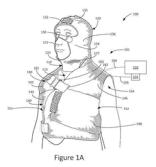
[0055] An exemplary compression garment system 100 including a garment 101
(e.g.,
compression garment) configured to be positioned around at least a portion of
a body
(e.g., a human body 10 as shown in FIGS. 2A-2C) is shown in FIGS. 1A-1B. The
garment 101 may be positioned relative to the body in a variety of different
ways (e.g.,
relative to a head 14, a neck 11, an anterior portion of the body 10, a
posterior portion
- 12 -
CA 03000964 2018-04-04
WO 2017/062337
PCT/US2016/055272
of the body 10, a forehead 15, under a chin 18, a left and right cheek 16, 17,
a torso 20
as shown in FIGS. 2A-2C). For example, as shown in FIGS. 1A-1B the garment 101
is
positioned around the head, neck and torso of the body. In one or more
embodiments,
the garment 101 may also cover the arms, waist, legs, or any other portion of
the body.
[0056] As shown in FIGS. 1A-1B the garment 101 is positioned on the head,
neck and
torso of the body. In other embodiments, the garment 101 may include only
portions
positioned on the head and neck of the body. Still further, in other
embodiments, the
garment 101 may include only portions positioned on the head of the body. The
garment 101 may include a head garment portion 120 positioned proximate the
head
and a neck garment portion 110 positioned proximate the neck.
[0057] In one or more embodiments, the head garment portion 120 and the
neck garment
portion 110 may be coupled to one another. For example, the head garment
portion
120 and the neck garment portion 110 may be coupled to one another at the
posterior of
the body, the anterior of the body, along the portion in which the head and
neck
garment portions 120, 110 intersect, etc. Still further, in one or more
embodiments, the
head garment portion 120 and the neck garment portion 110 may be coupled to
one
another along the entire portion in which the head and neck garment portions
120, 110
intersect (e.g., where such portions lie next to one another) or only along
portions
thereof (e.g., leaving openings at the coupling region for the garment to flex
and adapt
to the body of the user).
[0058] The garment 101 may also include a torso garment portion 140
configured to be
positioned proximate the torso of the body. In one or more embodiments, the
torso
garment portion 140 may be couplable to the neck garment portion 110 (e.g.,
the torso
garment portion 140 may be separate from the head garment or the head and neck
garment, may be removably couplable to the head garment or the head and neck
garment, for example, using hook and loop fasteners, etc.). For example, torso
garment
portion 140 and the neck garment portion 110 may be coupled to one another at
the
posterior of the body, the anterior of the body, along the portion in which
the torso
garment portion 140 and neck garment portion 110 intersect, etc. Still
further, in one or
more embodiments, the torso garment portion 140 and the neck garment portion
110
may be coupled to one another along the entire portion in which the torso
garment
- 13 -
CA 03000964 2018-04-04
WO 2017/062337
PCT/US2016/055272
portion 140 and neck garment portions 110 intersect (e.g., where such portions
lie next
to one another) or only along portions thereof (e.g., leaving openings at the
coupling
region for the garment to flex and adapt to the body of the user).
[0059] As shown in FIGS. 1A-1B, the garment 101 may also include an open
region 115
between the neck garment portion 110 and the torso garment portion 140
proximate the
anterior portion of the neck and adjacent the trachea when the garment 101 is
positioned on the body. The open region 115 may allow access to the airway of
an
individual wearing the garment 101.
[0060] The garment 101 may include pressure applying regions (e.g., as
shown in FIGS.
3-7) located at regions of the garment 101. Each of the pressure applying
regions may
be controllable or configurable to apply pressure to a portion of the body.
For example,
the head garment portion 120 may include head pressure applying regions that
are
controllable or configurable to apply pressure to one or more portions of the
head (e.g.,
to the forehead, cheeks, under the chin, posterior head), the neck garment
portion 110
may include neck pressure applying regions that are controllable or
configurable to
apply pressure to one or more portions of the neck (e.g., posterior neck
regions, side
neck regions, etc.), and the torso garment portion 140 may include torso
pressure
applying regions controllable or configurable to apply pressure to one or more
portions
of the torso (e.g., torso regions under each arm, the anterior torso, the
posterior torso,
etc.). As shown in FIGS. 1A-1B, the garment 101 may include an exterior
material
covering the pressure applying regions.
[0061] The head garment portion 120 may be configured to be donned on the
head of the
body. In other words, the head garment portion 120 may be positioned on and
secured
to the head of the body (e.g., secured using fasteners across the nose,
fasteners across
the forehead, fasteners under the chin, fasteners over the top of the head,
etc.). For
example, such fastening apparatus may allow one garment to be adjusted for use
with
different size and shaped body parts. In one or more embodiments, the head
garment
portion 120 may be described as configured to be positioned around both sides
of the
head of the body from the posterior of the head to the anterior of the head.
[0062] The head garment portion 120 may include a posterior head garment
portion 128,
a right head garment portion 134, and a left head garment portion 136. The
posterior
- 14 -
CA 03000964 2018-04-04
WO 2017/062337
PCT/US2016/055272
head garment portion 128 may be positionable proximate a posterior of the head
of the
body. The right head garment portion 134 may extend from the posterior head
garment
portion 128 and be positionable on (e.g., wrapped around) a right side of the
head from
the posterior of the head to an anterior of the head. The left head garment
portion 136
may extend from the posterior head garment portion 128 and be positionable on
(e.g.,
wrapped around) a left side of the head from the posterior of the head to the
anterior of
the head. The posterior head garment portion 128, the right head garment
portion 134,
and the left head garment portion 136 (or each of such portions) may include
pressure
applying regions (e.g., each of the one or more head pressure applying regions
for
applying compression on regions of the body associated with each of such
portions, one
or more head pressure applying regions for applying compression on one or more
regions of the body corresponding to one or more portions of the garment,
etc.) that are
configurable or controllable to apply pressure to the posterior of the head,
the right side
of the head, and the left side of the head.
[0063] The head garment portion 120 may also include a right cheek
garment portion 122
and a left cheek garment portion 124. The right cheek garment portion 122 may
be
positionable proximate a right cheek of the head and the left cheek garment
portion 124
may be positionable proximate a left cheek of the head. Each of the right and
left cheek
garment portions 122, 124 may include pressure applying regions (e.g., one or
more
cheek pressure applying regions) that may be configurable or controllable to
apply
pressure to a portion of cheek. The head garment portion 120 may also include
an
under chin garment portion 125. The under chin garment portion 125 may include
pressure applying regions (e.g., one or more under chin pressure applying
regions) that
may be configurable to apply pressure to a portion under the chin (e.g., at
the "waddle"
area).
[0064] The head garment portion 120 may be donned on the head of the
body in a variety
of different ways. For example, portions of the head garment portion 120 may
be
attached to other portions of the head garment portion 120 using a variety of
different
straps or connection elements. Any suitable connection apparatus may be used
for
donning the head garment portion 120 or any other garment portion described
herein,
such as flexible or rigid connection elements, hook and loop fasteners, straps
connected
- 15 -
CA 03000964 2018-04-04
WO 2017/062337
PCT/US2016/055272
to the garment, additional or separate connection garment elements or straps,
mating
hooks, elements shaped to form to a body part (such as the bridge of the
nose), etc.
[0065] These straps and connection elements may keep portions of the head
garment
portion 120 (e.g., surfaces associated with pressure applying regions) close
to the
surface of body such that the head garment portion 120 may effectively apply
pressure
to a particular portion of the body (e.g., the cheeks, under the chin,
forehead, temples),
such as, for example, when fluid is provided to cells of pressure applying
regions. In
other words, the straps or connection elements may assist in preventing the
head
garment portion 120 from moving away from the surface of portion of the body
when
pressure is being applied using pressure applying regions (e.g., such as when
fluid is
provided to cells of pressure applying regions) and instead, e.g., stay near
the portion of
the body such that pressure may be effectively applied. The different straps
or
connection elements keep the garment portions from moving away from the body
as
pressure is being applied such that even pressure applying regions (e.g., to
apply
pressure evenly) at edges of the garment are maintained in position during
application
of pressure to body regions adjacent such edges (e.g., garment edges proximate
the
cheeks of the head, garment edges near the chin of the head, garment edges
near under
the chin, garment edges near the temples of the head, etc.).
[0066] For example, the head garment portion 120 may include the under
chin garment
portion 125, one or more nasal connection elements 130, a forehead garment
portion
132, a top head strap 137, and a posterior head strap 138, each of which may
act as
straps or connection elements to keep the head garment portion 120 in place.
The under
chin garment portion 125 may include one or more under chin connection
elements 127
configured to connect the right cheek garment portion 122 and the left cheek
garment
portion 124. The one or more under chin connection elements 127 may also be
configured for use in donning the head garment portion 120 on the head of the
body
(e.g., tightening the head garment portion 120 into place on the head). In
other words,
the one or more under chin connection elements 127 may pull the right and left
cheek
garment portions 122, 124 closer to one another when the head garment portion
120 is
positioned on the head to assist in donning the head garment portion 120 on
the head.
- 16 -
CA 03000964 2018-04-04
WO 2017/062337
PCT/US2016/055272
[0067] The one or more nasal connection elements 130 may be positionable
proximate a
nasal bridge of the head and configured to connect the right cheek garment
portion 122
and the left cheek garment portion 124 to, e.g., maintain the head garment
portion 120
and right and left cheek garment portions 122, 124 proximate the surface of
the head
and cheeks. For example, the one or more nasal connection elements 130 may
include
a rigid portion shaped to be positioned adjacent the surface of the nasal
bridge of the
head (e.g., which rigid portion may be connected to the right cheek garment
portion
122 and the left cheek garment portion 124 by one or more flexible portions).
[0068] The forehead garment portion 132 may be positionable proximate a
forehead of
the head. The forehead garment portion 132 may include one or more forehead
connection elements that may be configured for use in donning the head garment
portion 120 on the head. In other words, the one or more forehead connection
elements
may pull one portion of the head garment portion 120 closer to another portion
of the
head garment portion 120 to position (e.g., secure) the head garment portion
120 on the
head of the body. In one or more embodiments, the head garment portion 120 may
include one or more straps positioned proximate the top of the head and
configured to
assist in donning the head garment portion 120 on the head. For example, the
top head
strap 137 and the posterior head strap 138 may be positioned proximate the top
of the
head and the posterior of the head, respectively, and may assist in donning
the head
garment portion 120 to the head. In one or more embodiments, the top head
strap 137
and the posterior head strap 138 may cover the entire top of the head. As
shown in
FIGS. 1A-1B, the head garment portion 120 defines a head open region 135
proximate
a top portion of the head and, e.g., between the top head strap 137 and the
posterior
head strap 138.
[0069] One will recognize that any number of straps or connection elements
may be used
to connect different portions of the head garment such that the pressure
applying
regions thereof are properly positioned adjacent desired regions of the head
and
maintained in positioned as pressure is being applied either dynamically or
statically.
[0070] The neck garment portion 110 coupled to the head garment portion
120 is shown
in FIGS. 1A-1B. The neck garment portion 110 may be configured to be donned on
a
neck of the body. In one or more embodiments, the neck garment portion 110 may
be
- 17 -
CA 03000964 2018-04-04
WO 2017/062337
PCT/US2016/055272
described as configured to be positioned around both sides of the neck from
the
posterior of the neck to the anterior of the neck. The neck garment portion
110 may
include pressure applying regions (e.g., one or more neck pressure applying
regions)
that may be configurable or controllable to apply pressure to a portion of the
neck.
[0071] The neck garment portion 110 may include a first neck garment
portion (e.g.,
right neck garment portion 112) and a second neck garment portion (e.g., left
neck
garment portion 114). The first neck garment portion may be positionable
proximate a
right portion or side of the neck and the second neck garment portion may be
positionable proximate a left portion or side of the neck. In one or more
embodiments,
the first neck garment portion (e.g., right neck garment portion 112) may be
described
as being positionable on (e.g., wrapped around) a right side of the neck from
a posterior
of the neck to an anterior of the neck and the second neck garment portion
(e.g., left
neck garment portion 114) may be described as being positionable on (e.g.,
wrapped
around) a left side of the neck from the posterior of the neck to the anterior
of the neck.
[0072] In one or more embodiments, the first neck garment portion is
separate from the
second neck garment portion (e.g., one portion may include pressure applying
regions
separate from those in the other portion). In other embodiments, the first and
second
garment portions may be one piece. Each of the first and second neck garment
portions
may be configurable or controllable to apply pressure to the right and left
sides of the
neck, respectively. For example, the pressure applying regions of first and
second neck
garment portions may be controllable or configurable to apply pressure
alternately
between each of the first and second neck garment portions, or simultaneously.
Specifically, the pressure applying regions of first and second neck garment
portions
may be controllable or configurable to apply pressure alternately during a
therapy cycle
of a therapy period (e.g., first neck garment portion then second neck garment
portion
then first neck garment portion and so on) between each of the first and
second neck
garment portions to help minimize the chances of an individual passing out as
lymph
passes from the head through the neck to the torso during compression therapy.
[0073] The garment 101 may also include a torso garment portion 140
positionable
proximate a torso of the body as shown in FIGS. 1A-1B. In one or more
embodiments,
the torso garment portion 140 may be described as configured to be positioned
around
- 18 -
CA 03000964 2018-04-04
WO 2017/062337
PCT/US2016/055272
both sides of the torso from the posterior of the torso to the anterior of the
torso. The
torso garment portion 140 may include pressure applying regions (e.g., one or
more
torso pressure applying regions) configurable or controllable to apply
pressure to one or
more portions of the torso. In one or more embodiments, the torso garment
portion 140
may be coupled to the head garment portion 120. Further, in one or more
embodiments, the neck garment portion 110 may be coupled between at least a
portion
of the head garment portion 120 and at least a portion of the torso garment
portion 140.
In yet other embodiments, the torso garment portion 140 may not be coupled to
either
the head garment portion 120 or the neck garment portion 110. Further, the
torso
garment portion 140 may include a collar portion locatable proximate the neck
of the
body (e.g., usable to cover the neck of the body with or without the neck
garment
portion, for example, removably couplable to the neck garment portion,
overlapping
with the neck garment portion when donned, etc.).
[0074] The torso garment portion 140 may include a posterior torso garment
portion 150,
a right torso garment portion 151, and a left torso garment portion 152. The
posterior
torso garment portion 150 may be positionable proximate a posterior of the
torso of the
body, the right torso garment portion 151 may extend from the posterior torso
garment
portion 150 and be positionable to the anterior of the torso, and the left
torso garment
portion 152 may extend from the posterior torso garment portion 150 and be
positionable to the anterior of the torso. In one or more embodiments, the
right torso
garment portion 151 and the left torso garment portion 152 may overlap
proximate the
anterior of the torso when the garment 101 is positioned on the body (e.g., as
shown in
FIG. 1A, at least a portion of the left torso garment portion 152 overlaps a
portion of
the right torso garment portion 151). In one or more embodiments, the right
torso
garment portion 151 may define a right arm opening 153 proximate a right arm
of the
body such that the right arm may extend outward from the garment 101 and the
left
torso garment portion 152 may define a left arm opening 154 proximate a left
arm of
the body such that the left arm may extend outward from the garment 101.
[0075] The right and left torso garment portions 151, 152 may be coupled
to each other
after donning the torso garment portion 140 on the torso of the body to attach
(e.g.,
secure) the torso garment portion 140 to the torso. The right torso garment
portion 151
- 19 -
CA 03000964 2018-04-04
WO 2017/062337
PCT/US2016/055272
may be coupled to the left torso garment portion 152 in any suitable manner.
For
example, the right and/or left torso garment portions 151, 152 may include
fastening
apparatus to, e.g., fasten or couple a region of the right torso garment
portion 151 to a
region of the left torso garment portion 152. Such fastening apparatus may
include
hook and loop fasteners, or any other fasteners described herein.
[0076] Further, for example, the garment 101 may include fastening
apparatus 180 (e.g.,
fastening structures) configured to couple the right torso garment portion 151
to the left
torso garment portion 152 (e.g., proximate the anterior of the torso). For
example, the
fastening apparatus 180 may include a right strap 181 couplable to the right
torso
garment portion 151, a left strap 182 couplable to the left torso garment
portion 152,
and a fastener 183 configured to couple the right strap 181 to the left strap
182. The
fastener 183 may include a right clasp coupled to the right strap 181 and a
left clasp
coupled to the left strap 182. The right clasp may engage the left clasp to
secure the
fastener 183. The right and left straps 181, 182 may be couplable on the right
and left
torso garment portions 151, 152, respectively, using hook and loop fasteners.
In other
words, the right and left straps 181, 182 may be adjustable on the right and
left torso
garment portions 151, 152 and then coupled together using the fastener 183
(e.g., such
as user releasable mating elements, etc.). This allows the right and left
straps 181, 182
to be placed on the torso garment portion 140 in an initial fitting of the
torso garment
portion 140 on a patient, but then the torso garment portion 140 may be donned
and
doffed with more ease using the fastener 183. For example, it provides the
torso
garment portion 140 to be easily released and re-engaged by the individual
wearing the
torso garment portion 140.
[0077] In one or more embodiments, the fastening apparatus 180 may include
a right
fastening portion that is removably couplable to the torso garment portion 140
(e.g., at
the right torso garment portion 151) and a left fastening portion that is
removably
couplable to the torso garment portion 140 (e.g., at the left torso garment
portion 152).
The right and left fastening portions may be coupled to the torso garment
portion 140
using, e.g., hook and loop fasteners or any other suitable fastener. The right
and left
fastening portions may be coupled together using a zipper or any other
suitable way to
couple the portions together. This design allows the right and left fastening
portions to
- 20 -
CA 03000964 2018-04-04
WO 2017/062337
PCT/US2016/055272
be placed initially to fit the torso garment portion 140 and then the torso
garment
portion 140 may be donned and doffed (e.g., tightened and loosened) through
zipping
and unzipping the zipper. In other words, the right and left fastening
portions may stay
attached to the torso garment portion 140 and only the zipper would need to
move to
don and doff the torso garment portion 140.
[0078] The right torso garment portion 151 may include a right chest
garment portion
142 and a right axillary garment portion 144. Each of the right chest garment
portion
142 and the right axillary garment portion 144 may extend from the posterior
torso
garment portion 150 to the anterior of the torso. The right chest garment
portion 142
may extend from a right shoulder of the torso towards a right anterior region
of the
torso (e.g., right side of chest, right side of lower abdomen). The right
axillary garment
portion 144 may be positionable proximate a right under arm region of the
torso.
[0079] The left torso garment portion 152 may include a left chest garment
portion 146
and a left axillary garment portion 148. Each of the left chest garment
portion 146 and
the left axillary garment portion 148 may extend from the posterior torso
garment
portion 150 to the anterior of the torso. The left chest garment portion 146
may extend
from a left shoulder of the torso towards a left anterior region of the torso
(e.g., left side
of chest, left side of lower abdomen). The left axillary garment portion 148
may be
positionable proximate a left under arm region of the torso.
[0080] The compression garment system 100 may also include a controller
102 or control
apparatus configured to control the pressure applied to the portion of the
body by each
of the pressure applying regions of the garment 101. For example, the
controller 102
may control the pressure applied to the portion of the body by each of the
pressure
applying regions independent from one another or at the same time. Further,
for
example, the pressure applying regions may be controlled in groups or
combinations.
In one or more embodiments, the controller 102 may be configured to control
the
pressure applying regions in a variety of different sequences (e.g., applying
pressure in
a predetermined manner) that may be, e.g., suitable for carrying out
lymphedema
therapy.
[0081] Further, the controller 102 may control the pressure based on one
or more
pressures measured by one or more pressure sensors associated with the garment
101
-21 -
CA 03000964 2018-04-04
WO 2017/062337
PCT/US2016/055272
(e.g., sensors provided in the garment 101 proximate the pressure applying
regions).
One or more compression garments that may be modified with features (e.g.,
sensors)
described herein may be similar to and include one or more features found in
U.S. Pat.
No. 6,860,862 entitled "Lymphedema Treatment System," U.S. Pat. No. 6,966,884
entitled "Lymphedema Treatment System," U.S. Pat. No. 6,179,796 entitled
"Lymphedema treatment system," and U.S. Pat. No. 6,645,165 entitled
"Lymphedema
treatment system," which are herein incorporated by reference.
[0082] In one or more embodiments, a control apparatus or controller 102
(e.g., one or
more processors employing one or more programs or routines carrying out one or
more
methods or processes and implemented with one or more types of memory) may be
configured to control the system and/or one or more elements thereof (e.g.,
providing
compression therapy by the one or more pressure applying regions, etc.). In
one or
more embodiments, the control apparatus may be configured to control the
compression
system using wired and/or wireless technology.
[0083] The methods and/or logic and/or configurations described in this
disclosure,
including those attributed to the systems, or various constituent components,
may be
implemented, at least in part, in hardware, software, firmware, or any
combination
thereof. For example, various aspects of the techniques may be implemented
within
one or more processors, including one or more microprocessors,
microcontrollers,
DSPs, ASICs, FPGAs, or any other equivalent integrated or discrete logic
circuitry, as
well as any combinations of such components, or other devices. The term
"processor"
or "processing circuitry" may generally refer to any of the foregoing logic
circuitry,
alone or in combination with other logic circuitry, or any other equivalent
circuitry.
[0084] Such hardware, software, and/or firmware may be implemented within
the same
device or within separate devices (e.g., within the system, outside of the
system, or a
combination of both) to support the various operations and functions described
in this
disclosure. In addition, any of the described components may be implemented
together
or separately as discrete but interoperable logic devices. Description of
different
features is intended to highlight different functional aspects and does not
necessarily
imply that such features must be realized by separate hardware or software
components. Rather, functionality may be performed by separate hardware or
software
- 22 -
CA 03000964 2018-04-04
WO 2017/062337
PCT/US2016/055272
components, or integrated within common or separate hardware or software
components.
[0085] When implemented in software, the functionality ascribed to the
systems and
methods described in this disclosure may be embodied as instructions and/or
logic on a
computer-readable medium such as RAM, ROM, NVRAM, EEPROM, FLASH
memory, magnetic data storage media, optical data storage media, or the like.
The
instructions and/or logic may be executed by one or more processors to support
one or
more aspects of the functionality described in this disclosure.
[0086] Further, the compression garment system 100 may include a pump 103
that may
be controlled by the controller 102 to provide a fluid to/from the one or more
cells (e.g.
one or more cells 803 as shown in FIG. 8A) of each of the pressure applying
regions,
e.g., a fluid such as a liquid or gas in the cells, so as to apply a
compression therapy
when the compression garment 101 includes one or more fluid filled cells. For
example, the pump 103 may be connected to one or more of the plurality of
cells
corresponding to the plurality of pressure applying regions by a plurality of
lines or
tubing 105 so as to provide flow of fluid thereto or removal of fluid
therefrom.
[0087] Further, in one or more embodiments, as shown in FIGS. 1A-1B, the
controller
102 may be connected to one or more components of the compression garment
system
via one or more electrical lines and/or wirelessly, as represented generally
by dashed
lines 104. For example, controller 102 may be connected to communicate and
control
the pressure applying regions (e.g., such as electrically actuatable pressure
applying
regions of the garment configured to apply pressure to the body) either with
use of
physical electrical connections and/or wirelessly.
[0088] The controllable pressure applying regions of the garment 101 under
control of
controller 102 allows the system 100 to provide compression therapy to an
individual
(e.g., a patient) wearing the garment 101 such that lymph flows throughout the
body 10
in desired directions, e.g., such as directions 40 as shown in FIG. 2A. In
other words,
by controlling the pressure applying regions in a variety of different
sequences (e.g.,
applying pressure in a predetermined manner), for example, lymph may flow
generally
from the head 14 of the body 10 towards the neck 11 of the body 10. For
example, the
lymph may be controlled to flow from an anterior 30 of the head 14 towards a
posterior
- 23 -
CA 03000964 2018-04-04
WO 2017/062337
PCT/US2016/055272
32 of the head 14 and downwards towards the neck 11. Specifically, for
example, the
lymph may flow from the forehead 15, the nasal bridge 19, and under the chin
18
towards the right cheek 17 and downwards towards the neck 11 (e.g., right side
of neck
12) and the posterior 25 of the torso 20. This direction 40 of lymph may
provide relief
to an individual by moving excess lymph from the head 14, and ultimately,
moving
such lymph towards the torso 20 (e.g., trunk, shoulders, chest, back, waist,
etc.).
[0089] The various nodes located in the head 14 and neck 11 of the body 10
are shown in
FIG. 2B. For example, the submental lymph nodes 52 are located the under chin
18 of
the head 14 and the parotid lymph nodes 50 are located proximate the right
cheek 17
and the left cheek 16 (parotid lymph nodes of left cheek 16 not shown in FIG.
2B). The
accumulation of lymph may occur near the parotid lymph nodes 50 and the
submental
lymph nodes 52 and may be pushed during compression therapy by the compression
garment donned on the body 10 towards the posterior 32 of the head 14 as
illustrated by
directional arrows 40 (e.g., by controlling the pressure applying regions
proximate at
least the cheeks 16, 17 and under the chin 18 in a predetermined manner). With
continued compression therapy (e.g., by controlling the pressure applying
regions
proximate at least the sides of the head 14 and the posterior 32 of the head
14), the
lymph then moves towards the submandibular lymph nodes 54 and superficial and
deep
cervical lymph nodes 56 located proximate the neck 11. The compression therapy
is
then configured (e.g., by controlling the pressure applying regions proximate
at least
the neck 11 in a predetermined manner) to move lymph towards the right infra
and
supra clavicular lymph nodes 58 and the left infra and supra clavicular lymph
nodes 60,
which are located at the base of the neck 11 and proximate the right shoulder
24 and the
left shoulder 23, respectively, and downwards towards the torso 20.
[0090] Various nodes located in the posterior 32 of the head 14 and the
torso 20 are
shown in FIG. 2C. During compression therapy using a compression garment
(e.g., by
controlling the pressure applying regions of the head garment 120 and neck
garment
110 in a predetermined manner), lymph may travel downward along the posterior
32 of
the body 10 from the head 14 towards the torso 20. For example, lymph may
travel
from the top of the head 14 towards the right retroauricular lymph nodes 66
and the
right occipital lymph nodes 70 located proximate the right side 12 of the neck
11 and
- 24 -
CA 03000964 2018-04-04
WO 2017/062337
PCT/US2016/055272
towards the left retroauricular lymph nodes 68 and the left occipital lymph
nodes 72
located proximate the left side 13 of the neck 11. The compression therapy
(e.g., by
controlling the pressure applying regions of the garment 101 in a
predetermined
manner) may then move the lymph further downwards from the head 14 and past
the
right and left shoulders 23, 24 and towards the torso 20. Specifically, the
lymph may
move towards the right axillary nodes 62 located proximate the right under arm
region
21 and the left axillary nodes 64 located proximate the left under arm region
22.
[0091] A plan view of the exemplary head garment portion 120 including one
or more
head pressure applying regions 121 is shown in FIG. 3. In one or more
embodiments,
at least a portion of the one or more head pressure applying regions 121 may
define an
arcuate shape. The one or more head pressure applying regions 121 may be
controllable (e.g., using controller 102 as shown in FIGS. 1A-1B) to apply
pressure to a
portion of the head when the head garment portion 120 is positioned on the
head. The
one or more head pressure applying regions 121 may be located in various
locations
within the head garment portion 120 to apply pressure to a variety of
different locations
on the head. For example, as described herein, the head garment portion 120
may
include the right head garment portion 134 positionable proximate a right side
of the
head and the left head garment portion 136 positionable proximate a left side
of the
head. The one or more head pressure applying regions 121 associated with the
right
and left head garment portions 134, 136 may be controllable to apply pressure
to the
right and left sides of the head, respectively.
[0092] In one or more embodiments, each of the one or more head pressure
applying
regions 121 may be configured in any suitable manner such that the regions 121
may be
controlled to apply pressure to a portion of the head. For example, the one or
more
head pressure applying regions 121 may include fluid chambers or cells,
pneumatic
pressure applying regions, actuatable elements applying pressure to regions,
hydraulic
pressure applying regions, etc. Specifically, the one or more head pressure
applying
regions 121 shown in FIGS. 3-7, as well as the other pressure applying regions
of the
other garment portions shown therein include one or more cells configured to
receive
fluid (e.g., air, liquid, etc.).
- 25 -
CA 03000964 2018-04-04
WO 2017/062337
PCT/US2016/055272
[0093] In one or more embodiments, the one or more head pressure applying
regions 121
may be configured to apply pressure to a portion of the head using the one or
more cells
through the control of fluid provided thereto, e.g., fluid flow, airflow, etc.
For
example, the head garment portion 120 may include one or more head garment
ports
139 through which fluid may be provided to the one or more cells (e.g., such
as with
use of pump 103 shown in FIGS. 1A-1B, under control of controller 102 with use
of a
sensor feedback system). Further, in one or more embodiments, the one or more
head
pressure applying regions 121 may include one or more head actuatable elements
(e.g.,
non-fluid receiving regions) configured to apply pressure to a portion of the
head (e.g.,
an electrical signal may be used to actuate an element within the garment,
such as
electrically actuatable fibers in the garment, such that the region including
such fibers
applies a pressure to a portion of the body). In one or more embodiments, the
one or
more head pressure applying regions 121 may include both one or more cells
configured to receive fluid and one or more head actuatable elements, both of
which
may be configured to apply pressure to a portion of the head.
[0094] Furthermore, as described herein, the head garment portion 120 may
include a
right cheek garment portion 122 and a left cheek garment portion 124, each of
which
may include one or more cheek pressure applying regions 123 (e.g., each of the
garment portions may include a portion of a pressure applying region shared
with other
garment portions, for example, the same pressure applying region may be used
to apply
compression at locations of the body associated with the right cheek and left
cheek, and
even the posterior garment portion). Each of the one or more cheek pressure
applying
regions 123 may be controllable to apply pressure to a portion of cheek to
assist in
moving lymph therefrom. Each of the right cheek garment portion 122 and the
left
cheek garment portion 124 may extend within the right and left head garment
portions
134, 136, respectively and terminate along right cheek and left cheek garment
edges
161, 162 (e.g., portions of such edges being located near the nasal bridge of
the head;
which portions may be coupled together by one or more nasal connection
elements
130).
[0095] Similarly, as described herein, the head garment portion 120 may
include the
under chin garment portion 125 that is configurable to apply pressure to a
portion under
- 26 -
CA 03000964 2018-04-04
WO 2017/062337
PCT/US2016/055272
the chin (e.g., a "waddle" area). For example, the under chin garment portion
125 may
include one or more under chin pressure applying regions 126. Each of the one
or more
under chin pressure applying regions 126 may be controllable to apply pressure
to a
portion under the chin to assist in moving lymph therefrom.
[0096] Also, as described herein, the head garment portion 120 may include
the posterior
head garment portion 128. The posterior head garment portion 128 may include
one or
more posterior head pressure applying regions 129. Each of the one or more
posterior
head pressure applying regions 129 may be controllable to apply pressure to a
portion
of the posterior of the head to move lymph therefrom (e.g., downward toward
the
torso).
[0097] Any number of pressure applying regions 121 may be configured in
the head
garment portion 120 such that they may be controlled to move lymph as
described, for
example, with reference to FIGS. 2A-2C. For example, as shown in FIG. 3, three
head
pressure applying regions 121 are implemented. However, any number of head
pressure applying regions 121 may be implemented (e.g., four head pressure
applying
regions 121 may be used). Each of the three pressure applying regions 121 may
extend
along the entire length of the head garment portion 120 positionable about the
head of a
user (e.g., from the front right side of the head around the posterior of the
head and
towards the front left side of the head). For example, each of the head
pressure
applying regions 121 may extend within the under chin garment portion 125, the
right
and left cheek garment portions 122, 124, and the posterior head garment
portion 128
(e.g., which may be beneficial in application of pressure in a downward and
rearward
manner on the head). In other words, the under chin garment portion 125, the
right and
left cheek garment portions 122, 124, and the posterior head garment portion
128 may
be integral with each other such that head pressure applying regions 121 may
span
across one or more specific portions. For example, application of pressure in
the outer
head pressure applying region 121 (e.g., next to edges 161, 162), followed by
application of pressure by more inward lying pressure applying regions, may
produce
desired lymph movement.
[0098] In one or more embodiments, the head pressure applying regions 121
may be
positioned such that pressure may be applied in a progression from the front
of the right
- 27 -
CA 03000964 2018-04-04
WO 2017/062337
PCT/US2016/055272
and left cheeks (e.g., at the anterior of the head) towards the posterior of
the head. For
example, pressure may be applied to a region proximate the right and left
cheek
garment portions 122, 124 at the anterior of the head, then proximate a middle
of the
cheeks at the right and left cheek garment portions 122, 124, and then
proximate a
portion of the cheeks closer to the posterior of the head at the right and
left cheek
garment portions 122, 124. In one or more embodiments, as pressure is being
applied
at the right and left cheek garment portions 122, 124 from the anterior of the
head
towards the posterior of the head, pressure may also be applied at the
posterior head
garment portion 128 from the top of the head towards the neck. In one or more
embodiments, this may occur due to the continuation of the three head pressure
applying regions 121 (e.g., as shown in FIG. 3) extending (e.g., along the
length of the
garment) between the right and left cheek garment portions 122, 124 and across
the
posterior head garment portion 128 (e.g., each of such pressure applying
regions may
be separate cells supplied by separate fluid conduits). As described herein,
when a
garment portion is described as including one or more pressure applying
regions, such
one or more pressure applying regions may be a separate pressure applying
region or
may be a pressure applying regions shared with one or more other garment
portions
(e.g., check garment portions and posterior head garment portions may use the
same
pressure applying region to apply compression to a body portion associated
therewith).
[0099] However, such head pressure applying regions 121 may include any
number of
different and separate cells along the wrappable length of the head garment
portion 120
and controllable to produce such desired lymph movement. For example, the head
pressure applying regions 121 may be separable between the right and left
cheek
garment portions 122, 124 and the posterior head garment portion 128. In other
words,
the head pressure applying regions 121 may be separated in any suitable way
that may
allow pressure to be applied from the right and left cheeks (e.g., proximate
the anterior
of the head) towards the posterior of the head and/or from the top of the
posterior of the
head towards the neck (e.g., to move lymph from the cheeks towards the neck at
the
posterior of the head). For example, the head pressure applying regions 121
may be
separated such that each head pressure applying region 121 may be
independently
controllable to move lymph in a desired direction (e.g., as shown in FIGS. 2A-
2C).
- 28 -
CA 03000964 2018-04-04
WO 2017/062337
PCT/US2016/055272
[00100] The head garment portion 120 may also include upper head garment
portions 131
proximate the top of the head to assist in applying pressure and assist in
donning the
head garment portion 120. For example, the upper head garment portions 131 may
include garment regions 155 adjacent the outermost pressure applying region of
the
three pressure applying regions 121 to assist in securing the pressure
applying regions
adjacent the surface of the head when pressure is being applied. Further, for
example,
the head garment portion 120 may include the posterior head strap 138
positionable
proximate the top and posterior of the head (e.g., using hook and loop
fastener
connection elements), the top head strap 137 positionable proximate the top of
the head
(e.g., a separate strap connectable to two different regions 163 of the head
garment
portion 120 across the top of the head when the head garment portion 120 is
donned),
and the forehead garment portion 132 positionable proximate the forehead
(e.g., using
hook and loop fastener connection elements).
[00101] The forehead garment portion 132 may be configurable to apply
pressure to a
portion of the forehead. In one or more embodiments, the forehead garment
portion
132 may include one or more forehead pressure applying regions 133
controllable to
apply pressure to a portion of the forehead. One will recognize that any
number of
upper head garment portions 131 may be used to secure the head garment portion
120
on the head. For example, although the figures provided herein show straps for
use in
donning the head garment portion 120, the head garment portion 120 may be
provided
in a stocking cap like configuration where no straps are used in the entire
top of the
head is covered.
[00102] A plan view of the exemplary neck garment portion 110 including one
or more
neck pressure applying regions 111 is shown in FIG. 4. In one or more
embodiments,
at least a portion of the one or more neck pressure applying regions 111 may
define an
arcuate shape. The one or more neck pressure applying regions 111 may be
controllable (e.g., using controller 102 as shown in FIGS. 1A-1B) to apply
pressure to a
portion of the neck when the neck garment portion 110 is positioned on the
neck.
[00103] In one or more embodiments, the neck garment portion 110 may
include a first
neck garment portion (e.g., right neck garment portion 112) and a second neck
garment
portion (e.g., left neck garment portion 114). Each of the first and second
neck garment
- 29 -
CA 03000964 2018-04-04
WO 2017/062337
PCT/US2016/055272
portions may include one or more neck pressure applying regions 111. In one or
more
embodiments, the one or more neck pressure applying regions 111 of the first
and
second neck garment portions may be separated by a divider 113. In other
words, the
divider 113 separates pressure applied by the one or more neck pressure
applying
regions 111 of the first neck garment portion 112 from the one or more neck
pressure
applying regions 111 of the second neck garment portion 114.
[00104] In one or more embodiments, each of the one or more neck pressure
applying
regions 111 may be configured such that they may be controlled to apply
pressure to a
portion of the neck. For example, the one or more neck pressure applying
regions 111
may include fluid chambers or cells, pneumatic pressure applying regions,
actuatable
elements applying pressure to regions, hydraulic pressure applying regions,
etc.
Specifically, the one or more neck pressure applying regions 111 may include
one or
more cells configured to receive fluid as shown in FIG. 4.
[00105] For example, in one or more embodiments, the one or more neck
pressure
applying regions 111 may be configured to apply pressure to a portion of the
head
using the one or more cells through the control of fluid provided thereto,
e.g., fluid
flow, airflow, etc. (e.g., such as with use of pump 103 shown in FIGS. 1A-1B,
under
control of controller 102 with use of a sensor feedback system). For example,
the neck
garment portion 110 may include one or more neck garment ports 119 through
which
fluid may be provided to the one or more cells. In one or more embodiments,
the neck
garment portion 110 may include two neck garment ports 119, one in each of the
right
and left neck garment portions 112, 114 (e.g., such as for use in alternating
application
of pressure between the right and left sides of the neck).
[00106] Further, in one or more embodiments, the neck pressure applying
regions 111
may include one or more neck actuatable elements (e.g., non-fluid receiving
regions)
configured to apply pressure to a portion of the neck (e.g., an electrical
signal may be
used to actuate an element within the garment, such as electrically actuatable
fibers in
the garment, such that the compartment including such fibers applies a
pressure to a
portion of the body). In one or more embodiments, the one or more neck
pressure
applying regions 111 may include both one or more cells configured to receive
fluid
and one or more neck actuatable elements.
- 30 -
CA 03000964 2018-04-04
WO 2017/062337
PCT/US2016/055272
[00107] Any number of pressure applying regions 111 may be configured in
the neck
garment portion 110 such that they may be controlled to move lymph as
described, for
example, with reference to FIGS. 2A-2C. For example, as shown in FIG. 4, one
pressure applying region 111 is implemented (e.g., although with use of the
dotted
additional port 119 and the divider 113, two pressure applying regions 111 is
also
shown as being implemented). The single pressure applying region 111 may
extend
along the entire length of the neck garment portion 110 positionable about the
neck of a
user. For example, the pressure applying region 111 may extend within the neck
garment portion 110 from a first end 211 to a second end 213. However, such
pressure
applying regions 111 may include any number of different and separate cells
along the
wrappable length of the neck garment portion 110 and controllable to produce
desired
lymph movement (e.g., multiple cells along the length, parallel cells along
the width,
etc.).
[00108] A plan view of the exemplary torso garment portion 140 including
one or more
torso pressure applying regions 141 is shown in FIG. 5. Any number of torso
pressure
applying regions 141 may be implemented (e.g., the torso garment portion 140
may
include eight torso pressure applying regions 141). In one or more
embodiments, at
least a portion of the one or more torso pressure applying regions 141 may
define an
arcuate shape (e.g., curved portions of the torso pressure applying regions
141
extending over the shoulders of a user from the posterior to the anterior).
For example,
arcuate shapes (e.g., of any of the portions of the garment) that may be
similar to and
include one or more features found in U.S. Pat. No. 6,860,862 entitled
"Lymphedema
Treatment System," U.S. Pat. No. 6,966,884 entitled "Lymphedema Treatment
System," U.S. Pat. No. 6,179,796 entitled "Lymphedema treatment system," and
U.S.
Pat. No. 6,645,165 entitled "Lymphedema treatment system," which are herein
incorporated by reference. The one or more torso pressure applying regions 141
may
be configured to be controlled (e.g., using controller 102 as shown in FIGS.
1A-1B) to
apply pressure to one or more portions of the torso when the torso garment
portion 140
is positioned on the torso.
[00109] The one or more torso pressure applying regions 141 may be located
in various
locations within the torso garment portion 140 to apply pressure to a variety
of different
-31-
CA 03000964 2018-04-04
WO 2017/062337
PCT/US2016/055272
locations on the torso. For example, the torso garment portion 140 may include
a right
torso garment portion 151 positionable proximate the right side of the torso,
a left torso
garment portion 152 positionable proximate the left side of the torso, and a
posterior
torso garment portion 150 positionable proximate the posterior of the torso.
The one or
more torso pressure applying regions 141 associated with the right, left, and
posterior
torso garment portions 151, 152, 150 may be controllable to apply pressure to
the right
side, left side, and posterior of the torso, respectively. In one or more
embodiments, the
right torso garment portion 151 may be described as positioned proximate a
right
anterior portion and right side of the torso and the left torso garment 152
may be
described as positionable proximate a left anterior portion and a left side of
the torso;
the torso pressure applying regions 141 associated with such regions may be
controllable or configured to apply pressure to each of the right and left
anterior
portions of the torso and the right and left sides of the torso.
[00110] In one or more embodiments, each of the one or more torso pressure
applying
regions 141 may be configured in any suitable manner such that the regions 141
may be
controlled to apply pressure to a portion of the torso to move lymph as
desired. For
example, the one or more torso pressure applying regions 141 may include fluid
chambers or cells, pneumatic pressure applying regions, actuatable elements
applying
pressure to regions, hydraulic pressure applying regions, etc. Specifically,
the one or
more torso pressure applying regions 141 may include one or more cells
configured to
receive fluid (e.g., air).
[00111] For example, in one or more embodiments, the one or more torso
pressure
applying regions 141 may be configured to apply pressure to a portion of the
torso
using the one or more cells through the control of fluid provided thereto,
e.g., liquid
flow, air flow, etc. For example, the torso garment portion 140 may include
one or
more torso garment ports 159 through which fluid may be provided to the one or
more
cells (e.g., such as with use of pump 103 shown in FIG. 1, under control of
controller
102 with use of a sensor feedback system).
[00112] Further, in one or more embodiments, the one or more torso pressure
applying
regions 141 may include one or more torso actuatable elements configured to
apply
pressure to a portion of the torso (e.g., an electrical signal may be used to
actuate an
- 32 -
CA 03000964 2018-04-04
WO 2017/062337
PCT/US2016/055272
element within the garment, such as electrically actuatable fibers in the
garment, such
that the compartment including such fibers applies a pressure to a portion of
the body).
In one or more embodiments, the one or more torso pressure applying regions
141 may
include both one or more cells configured to receive fluid and one or more
torso
actuatable elements.
[00113] Further, in one or more embodiments, the right torso garment
portion 151 may
include a right chest garment portion 142 positionable proximate the right
shoulder and
chest of the torso and a right axillary garment portion 144 positionable
proximate the
right under arm and right waist of the torso. The right chest garment portion
142 may
include one or more right chest pressure applying regions 143 controllable to
apply
pressure to a portion of the right chest and right shoulder. The right
axillary garment
portion 144 may include one or more right axillary pressure applying regions
145
controllable to apply pressure to a portion of the torso under the right under
arm of the
torso.
[00114] Still further, the left torso garment portion 152 may also include
a left chest
garment portion 146 positionable proximate the left shoulder and chest of the
torso and
a left axillary garment portion 148 positionable proximate the left under arm
and left
waist of the torso. The left chest garment portion 146 may include one or more
left
chest pressure applying regions 147 controllable to apply pressure to a
portion of the
left chest and left shoulder. The left axillary garment portion 148 may
include one or
more left axillary pressure applying regions 149 controllable to apply
pressure to a
portion of the torso under the left under arm. Each of the pressure applying
regions 141
of the torso garment portion 140 may be controllable to apply pressure to a
portion of
the torso to move lymph as desired (e.g., downward from the neck and shoulder
regions
to lower portions of the torso).
[00115] Any number of pressure applying regions 141 may be configured in
the torso
garment portion 140 such that they may be controlled to move lymph as
described, for
example, with reference to FIGS. 2A-2C. For example, as shown in FIG. 5, a
plurality
of pressure applying regions 141 are distributed in the torso garment portion
140. In
one or more embodiments, the plurality of pressure applying regions 141 may
include
an upper torso pressure applying region 261 (e.g., adjacent an upper edge 262
of the
- 33 -
CA 03000964 2018-04-04
WO 2017/062337
PCT/US2016/055272
torso garment portion 140) positionable for applying pressure to the upper
posterior
torso region and upper anterior torso region of the body. Further, in one or
more
embodiments, the plurality of pressure applying regions 141 may include a
lower torso
pressure applying region 263 (e.g., primarily extending in the axillary
garment portions
144, 148) positionable for applying pressure primarily to the lower posterior
torso
region and the lower anterior torso region of the body.
[00116] One or more of the pressure applying regions 141 may extend along
the entire
wrappable length of the torso garment portion 140 (e.g., the wrappable length
of the
torso garment portion 140 being a length of the curve extending from the left
chest
garment portion 146 to the right chest garment portion 142). For example, one
or more
of the pressure applying regions 141 may extend within the left chest garment
portion
146, the posterior torso garment portion 150, and the right chest garment
portion 142.
For example, application of pressure in the upper torso pressure applying
region 261
(e.g., next to edge 262), followed by application of pressure by lower
pressure applying
regions, may produce desired lymph movement. However, such pressure applying
regions 141 may include any number of different and separate cells within the
torso
garment portion 140 and controllable to produce desired lymph movement.
[00117] In one or more embodiments (e.g., as shown in FIGS. 1A-1B), the
right chest
garment portion 142, the right axillary garment portion 144, the left chest
garment
portion 146, and the left axillary garment portion 148 may be configured to
overlap
over a portion of the body (e.g., over the anterior portion of the torso of
the body). In
one or more embodiments, the right chest garment portion 142, the right
axillary
garment portion 144, the left chest garment portion 146, and the left axillary
garment
portion 148 may overlap such that the pressure applying regions 143, 145, 147,
149 are
positioned next to the portion of the body to which such pressure applying
regions are
to apply pressure for desired lymph movement. For example, right and left
chest
garment portions 142, 146 may be positioned on the body first, followed by the
right
and left axillary garment portions, 144, 148. Furthermore, the right axillary
garment
portion 144 may define a right axillary garment portion end 164 (e.g.,
terminating the
portion 144) that may be configured to be coupled (e.g., using hook and loop
fasteners)
- 34 -
CA 03000964 2018-04-04
WO 2017/062337
PCT/US2016/055272
to a left axillary garment portion end 168 that is defined by the left
axillary garment
portion 148 (e.g., terminating the portion 148).
[00118] Further, in one or more embodiments, the right and left chest
garment portions
142, 146 may be coupled to one another using one or more torso straps 185
(e.g.,
separate straps connectable, such as with use of hook and loop fasteners, to
two
different regions 142, 146 of the torso garment portion 140 across the chest
of the user
when the torso garment portion 140 is being donned). The one or more torso
straps 185
may be positioned along the right and left chest garment portions 142, 146 to
don the
torso garment portion 140 onto the torso of the body. In one or more
embodiments, the
fastening apparatus 180 (e.g., as shown in FIGS. 1A-1B) may include the one or
more
torso straps 185.
[00119] One will recognize that any number of connection elements may be
used to
connect regions of the torso garment portion 140 for securing the torso
garment portion
140 on the body. Further, one will recognize that the shape and size of the
torso
garment portion 140 may take one of various forms and is not limited to the
wing
shaped configuration of FIGS. 3-7. For example, the torso garment portion 140
may
take the form of a more vest-like structure with openings to receive a user's
arms as
described with reference to FIGS. 9-10. Further, for example, the torso
garment
portion 140 may also include arm garment portions (not shown) which extend
along a
least a portion of the user's arm from shoulder region of the torso garment.
[00120] As shown in FIGS. 3-7, each of the head garment portion 120, the
neck garment
portion 110, and the torso garment portion 140 is configured in a symmetrical
manner
generally with reference to the axis of a person's body. In other words, the
various
garment portions include sub-portions symmetrical about an axis. For example,
the
head garment portion 120 as shown in FIG. 3 is symmetrical about axis 201
(e.g., one
or more sub-portions, such as right cheek garment portion 122 and left cheek
garment
portion 124 may be symmetrical about axis 201). In one or more embodiments,
sub-
portions of one or more of the head garment portion 120, the neck garment
portion 110,
and the torso garment portion 140 which include pressure applying regions may
be
symmetrical about axis 201, while other portions the head garment portion 120,
the
neck garment portion 110, or the torso garment portion 140 may be non-
symmetrical.
- 35 -
CA 03000964 2018-04-04
WO 2017/062337
PCT/US2016/055272
Further, in one or more embodiments, non-symmetrical garments are contemplated
within the present disclosure (e.g., various garment portions may be non-
symmetrical to
accomplish one or more various functions such as related to donning or
securing the
garment on a user).
[00121] In one or more embodiments, the one or more pressure applying
regions of the
head garment portion 120, the neck garment portion 110, and the torso garment
portion
140 may be used in conjunction with one another. For example, the one or more
neck
pressure applying regions 111 may be controllable to apply a pressure to the
portion of
the neck after the one or more head pressure applying regions 121 are
controlled to
apply pressure to a portion of the head. In another example, the one or more
neck
pressure applying regions 111 may be controllable to apply pressure to the
portion of
the neck and the one or more head pressure applying regions 121 may be
controllable
to apply pressure to the portion of the head to move lymph from the head
towards the
neck and downward therefrom. In yet another example, the one or more under
chin
pressure applying regions 126, the one or more cheek pressure applying regions
123,
the one or more posterior head pressure applying regions 129, and the one or
more neck
pressure applying regions 111 may be configured or controllable to move lymph
from a
portion under the chin towards the portion of the cheek, from the portion of
the cheek
towards the portion of the posterior head, and from the portion of the
posterior head
towards the portion of the neck.
[00122] In one or more embodiments, the controller (e.g., controller 102 as
shown in
FIGS. 1A-1B) may be configured to control pressure applied by each of the one
or
more head pressure applying regions 121, the one or more neck pressure
applying
regions 111, and the one or more torso pressure applying regions 141 to move
lymph at
least from the head to the neck to the torso. In one or more embodiments, each
of the
head and torso pressure applying regions 121, 141 may be controllable to apply
pressure to move lymph at least from the left and right sides of the head
towards the
posterior of the head and from the posterior of the head downward towards the
torso.
[00123] In one or more embodiments, the head garment portion 120 may be
coupled to the
neck garment portion 110 as shown in FIG. 6. Any suitable manner may be used
to
couple the head and neck garment portions 120, 110. For example, such garment
- 36 -
CA 03000964 2018-04-04
WO 2017/062337
PCT/US2016/055272
portions may be coupled using stitching, welding, or any other coupling
technique to
form a unitary garment. For example, head garment portion 120 may be attached
to
neck garment portion 110 at respective seam lines 250, 251. In one or more
embodiments, the head garment portion 120 may be attached to the neck garment
portion 110 along the entire seam line 250, 251. Further, in one or more
embodiments,
for example, the head and neck garment portions 120, 110 may be coupled to one
another at select locations along the respective seam lines 250, 251 to
provide increased
flexibility for the head garment portion 120 to move relative to the neck
garment
portion 110. Specifically, the head and neck garment portions 120, 110 may be
coupled
such that there are one or more openings between the head and neck garment
portions
120, 110 proximate the posterior of the head. In one or more embodiments, the
head
garment portion 120 may be removably couplable to the neck garment portion
110, for
example, using flaps extending outward from one or both of the head garment
portion
120 and the neck garment portion 110. In other words, the head garment portion
120
and the neck garment portion 110 may be coupled and uncoupled using any
suitable
fastener at, e.g., the flaps extending outward from one or both.
[00124] In one or more embodiments, the head garment portion 120 and the
torso garment
portion 140 may be coupled to the neck garment portion 110 as shown in FIG. 7.
For
example, the head garment portion 120 may be coupled to the neck garment
portion
110 as described with reference to FIG. 6. Further, for example, any suitable
manner
may be used to couple the torso and neck garment portions 140, 110. For
example,
such garment portions may be coupled using stitching, welding, or any other
coupling
technique to form a unitary garment. For example, torso garment portion 140
may be
attached to neck garment portion 110 at respective seam lines 253, 252. Dashed
lines
108 illustrate the points at which the torso garment portion 140 and the neck
garment
portion 110 may be coupled together along the illustrated seam lines.
[00125] In one or more embodiments, the torso garment portion 140 may be
attached to
the neck garment portion 110 along the entire seam lines 253, 252. Further, in
one or
more embodiments, for example, the torso and neck garment portions 140, 110
may be
coupled to one another at select locations along the respective seam lines
253, 252 to
- 37 -
CA 03000964 2018-04-04
WO 2017/062337
PCT/US2016/055272
provide increased flexibility for the torso garment portion 140 to move
relative to the
neck garment portion 110.
[00126] Further, in one or more embodiments, the head, neck, and torso
garment portions
120, 110, 140 may be coupled to one another in a variety of different ways.
For
example, the torso garment portion 140 may be coupled to the neck garment
portion
110 such that the torso garment portion 140 has increased flexibility to move
relative to
the neck garment portion 110. For example, the neck and torso garment portions
110,
140 may be coupled to one another such that there are one or more openings
between
the neck and torso garment portions 110, 140 proximate the posterior of the
neck. In
one or more embodiments, the torso garment portion 140 may be coupled to the
head
garment portion 120 (e.g., directly coupled). For example, in one or more
embodiments, the head garment portion 120 and the neck garment portion 110 may
be
provided as a single head/neck garment portion that may be coupled to the
torso
garment portion 140. In other words, coupling of the head and neck garment
portions
120, 110 may include such garment portions being formed as a single unitary
garment
portion. In one or more embodiments, the torso garment portion 140 may be
removably couplable to the neck garment portion 110 and/or the head garment
portion
120, for example, using flaps extending outward from one or each of the torso
garment
portion 140, the head garment portion 120, and the neck garment portion 110.
For
example, the torso garment portion 140 may have flaps extending from the torso
garment portion 140 proximate the neck such that the flaps may have the
appearance of
a popped up collar. Therefore, the torso garment portion 140 may be coupled
and
uncoupled to the head garment portion 120 and/or the neck garment portion 110
using
any suitable fastener at, e.g., the flaps extending outward from one or both.
[00127] A cross-section of a portion 800 of an exemplary garment including
one or more
cells 803 which may be used in providing any of the garments described herein
is
shown in FIG. 8A. The garment portion 800 may define an exterior surface 801
and an
opposing interior surface 802. The interior surface 802 may be configured to
be
positioned closer to the human body than the exterior surface 801 when the
garment
portion 800 is positioned on the body. The one or more cells 803 may be
separated in
any way that isolates one cell of the one or more cells 803 from another cell
of the one
- 38 -
CA 03000964 2018-04-04
WO 2017/062337
PCT/US2016/055272
or more cells 803. For example, the one or more cells 803 may be separated by
welds
805.
[00128] The garment portion 800 may include one or more layers 804, with at
least one of
the one or more layers 804 including a compression layer 806. The compression
layer
806 may define a cavity in each of the one or more cells 803 that may be
configured to
receive a fluid. The compression layer 806 of each of the one or more cells
803 may
receive fluid from a source (e.g., from pump 103 shown in FIGS. 1A-1B) to
apply
pressure to body portion when garment portion 800 is worn by a user. For
example, the
fluid may be directed to each of the one or more cells 803 in a sequential or
in a
continuous manner from, e.g., an inlet to the garment portion 800 to an outlet
of the
garment portion 800, using a single port, etc.
[00129] Each of the one or more cells 803 may be (e.g., individually or in
groups) filled
with fluid to a pressure that is to be applied to the portion of the body by
the garment
portion 800. Each of the various pressure applying regions described herein
may
include, e.g., one of the one or more cells 803 or a plurality of the one or
more cells
803. In one or more embodiments, different pressure applying regions described
herein
may include, e.g., the same one or more cells, but may, e.g., be positioned at
different
locations on the garment.
[00130] A cross-section of another portion 850 of exemplary garment
including one or
more compression regions 853 which may be used in providing any of the
garments
described herein is shown in FIG. 8B. The garment portion 850 may define an
exterior
surface 851 and an opposing interior surface 852. The interior surface 852 may
be
configured to be positioned closer to the human body than the exterior surface
851
when the garment portion 850 is positioned on the body. The one or more
regions 853
may be separated or may not need to be separated from one another. In one
embodiment, for example, the one or more regions 853 may be separated by welds
855.
[00131] The garment 850 may include one or more layers 854, with at least
one of the one
or more layers 854 including a compression layer 857. The compression layer
857 may
include a variety of suitable components configured to apply pressure. For
example,
the pressure may be applied through the compression layer by an air or
pneumatic
system, a hydraulic system, an electro-mechanical system, actuated elements
(e.g., an
- 39 -
CA 03000964 2018-04-04
WO 2017/062337
PCT/US2016/055272
electrical signal may be used to actuate an element within the garment, such
as
electrically actuatable fibers in the garment, such that the compartment
including such
fibers applies a pressure to a portion of the body), a cable/lace tensioning
system, or
any other system that is configured to apply pressure to the portion of the
body through
the garment portion 850.
[00132] In at least one embodiment, the compression layer 857 may be a
plurality of
actuated elements configured to apply pressure to the portion of the body
(e.g.,
actuatable material, such as nitinol, or any other compressing devices). The
compression layer 857 of each of the one or more regions 853 may apply
pressure to
body portion when the garment portion 850 is worn by a user. For example,
pressure
may be applied by each of the one or more regions 853 in a sequential or in a
continuous manner over the one or more regions 853. Each of the various
pressure
applying regions described herein may include, e.g., one of the one or more
regions 853
or a plurality of the one or more regions 853. In one or more embodiments,
different
pressure applying regions described herein may include, e.g., the same one or
more
regions, but may, e.g., be positioned at different locations on the garment
portion 850.
[00133] The garment portions 800, 850, described in FIGS. 8A-8B (and hence
as shown in
FIGS. 1-7 and 9-10), may also be associated with one or more pressure sensors
818,
868 configured to measure pressure applied to the portion of the body by the
garment
portions 800, 850. The pressure sensors 818, 868 may be located at a variety
of
positions along the garment portions 800, 850. For example, the pressure
sensors 818,
868 may be positioned (e.g., at an equal distance apart or as necessary) along
the length
of the garment portions 800, 850. The pressure sensors 818, 868 may be located
adjacent the one or more of the pressure applying regions or multiple layers
804, 854 of
the garment portions 800, 850.
[00134] For example, one layer of material may encompass pressure sensors
818, 868
including pressure sensing regions corresponding to the one or more pressure
applying
regions and/or corresponding to the one or more cells 803, 853. In one or more
embodiments, the pressure sensors 818, 868 may be positioned on a side of the
garment
portions 800, 850 that may be proximate the portion of the body (e.g., the
interior
surface 802, 852, etc.). The pressure sensors 818, 868 may be positioned for
sensing
- 40 -
CA 03000964 2018-04-04
WO 2017/062337
PCT/US2016/055272
pressure at, e.g., each pressure applying region, each of the one or more
cells 803, 853,
a manifold for multiple chambers, etc.
[00135] Pressure sensor apparatus may be implemented for sensing pressure
in a plurality
of different manners at, e.g., each pressure applying region, each air cell or
chamber, a
manifold for multiple chambers, etc. The pressure sensor apparatus may be
configured
to measure pressure in a variety of different ways, e.g., one sensor for each
pressure
applying region, a single sensor for all of the pressure applying regions,
etc.
Additionally, the controller may be configured to control the pressure applied
to the
portion of the body based on the measured pressure. For example, pressure
sensing
apparatus may take the form of using pressure sensor within the garment
described in
U.S. Patent No. 9,027,408 entitled "Elastomeric Particle Having An
Electrically
Conducting Surface, A Pressure Sensor Comprising Said Particles, A Method For
Producing Said Sensor And A Sensor System Comprising Said Sensors," or a pump
or
control apparatus (e.g., 102) may be provided with pressure sensing
functionality (e.g.,
measuring pressures of air in cells as part of the pump apparatus) such as
described in
U.S. Patent No. 7,947,003 entitled "Pressurized Medical Device," all of which
are
incorporated by reference herein.
[00136] Another exemplary compression garment system 900 is illustrated in
FIGS. 9-10.
The compression garment system 900 may include any of the features shown
and/or
described herein with reference to FIGS. 1-8, and further, any garments
described with
reference to FIGS. 1-8 may use any features shown and/or described with
reference to
FIGS. 9-10. The compression garment system 900 includes a garment 901
configured
to be positioned around at least a portion of a body (e.g., a human body 10 as
shown in
FIGS. 2A-2C). The garment 901 may be positioned relative to the body in a
variety of
different ways. For example, as shown in FIGS. 9-10, the garment 901 is
positioned
around the head, neck, and torso of the body.
[00137] As shown in FIGS. 9-10, the garment includes a head garment portion
920
positioned proximate the head, a neck garment portion 910 positioned proximate
the
neck, and a torso garment portion 940 positioned proximate the torso. The head
garment portion 920 may be coupled to the neck garment portion 910 and the
neck
garment portion 910 may be coupled to the torso garment portion 940. In one or
more
-41 -
CA 03000964 2018-04-04
WO 2017/062337
PCT/US2016/055272
embodiments, the head garment portion 920 may be coupled to the torso garment
portion 940. As shown in FIGS. 9-10, the garment 901 may also include an open
region 915 between the neck garment portion 910 and the torso garment portion
940
proximate the anterior portion of the neck and adjacent the trachea when the
garment
901 is positioned on the body. The open region 915 may allow access to the
airway of
a patient wearing the garment 901.
[00138] The garment 901 may include pressure applying regions located
at regions in each
portion of the garment 901. Each of the pressure applying regions may be
controllable
or configured to apply pressure to a portion of the body. For example, the
head
garment portion 920 may include one or more head pressure applying regions 921
that
are controllable or configured to apply pressure to one or more corresponding
portions
of the head, the neck garment portion 910 may include one or more neck
pressure
applying regions 911 that are controllable or configured to apply pressure to
one or
more corresponding portions of the neck, and the torso garment portion 940 may
include one or more torso pressure applying regions 941 controllable or
configured to
apply pressure to one or more corresponding portions of the torso.
[00139] The head garment portion 920 may be configured to be donned on
the head of the
body. In one or more embodiments, the head garment portion 920 may be
described as
configured to be positioned around both sides of the head from the posterior
of the head
to the anterior of the head. The head garment portion 920 may include a
posterior head
garment portion 928, a right head garment portion 934, and a left head garment
portion
936. The posterior head garment portion 928 may be positionable proximate a
posterior of the head, the right head garment portion 934 may extend from the
posterior
head garment portion 928 and be positionable on the right side of the head
from the
posterior of the head to the anterior of the head, and the left head garment
portion 936
may extend from the posterior head garment portion 928 and be positionable on
the left
side of the head from the posterior of the head to the anterior of the head.
The head
garment portion 920 may also include a right cheek garment portion 922
positionable
proximate the right cheek and a left cheek garment portion 924 positionable
proximate
the left cheek.
- 42 -
CA 03000964 2018-04-04
WO 2017/062337
PCT/US2016/055272
[00140] The head garment portion 920 may include one or more head pressure
applying
regions 921. For example, each of the right head garment portion 934, the left
head
garment portion 936, and the posterior head portion 928 of the head garment
portion
920 may include one or more portions of the one or more head pressure applying
regions 921. Additionally, the right and left cheek garment portions 922, 924
may
include one or more cheek pressure applying regions 923 configured or
controllable to
apply pressure to a portion of the cheek. The head pressure applying regions
921, and,
e.g., the one or more cheek pressure applying regions 923, may work together
to help
move lymph out of the head and towards the neck and torso.
[00141] The head garment portion 920 may also include a forehead garment
portion 932
and an under chin garment portion 925. The forehead garment portion 932 and
the
under chin garment portion 925 may be configured to couple a first portion of
the head
garment portion 920 to a second portion of the head garment portion 920 to
assist in
donning and positioning the head garment portion 920 on the head. For example,
the
under chin garment portion 925 may include one or more under chin connection
elements 927 configured to couple the right cheek garment portion 922 to the
left cheek
garment portion 924. The forehead garment portion 932 and the under chin
garment
portion 925 may be used to keep portions of the head garment portion 920
(e.g., the
right and left cheek garment portions 922, 924) close to the head when the one
or more
head pressure applying regions 921 are applying pressure to the head. For
example, the
one or more head pressure applying regions 921 may move the head garment
portion
920 away from the body when applying pressure because that direction is the
path of
least resistance.
[00142] The forehead garment portion 932 and the under chin garment portion
925 may be
configured to prevent the head garment portion 920 from moving in undesired
directions and ensure that the one or more head pressure applying regions 921
are
applying pressure to the head when the head garment portion 920 is donned on
the
head. In one or more embodiments, the head garment portion 920 may include one
or
more nasal connection elements (not shown) positionable proximate a nasal
bridge of
the head and configured to connect the first portion of the head garment
portion 920
- 43 -
CA 03000964 2018-04-04
WO 2017/062337
PCT/US2016/055272
(e.g., the right cheek garment portion 922) to the second portion of the head
garment
portion 920 (e.g., the left cheek garment portion 924).
[00143] In one or more embodiments, the forehead garment portion 932 and
the under
chin garment portion 925 may be configured to apply pressure to a portion of
the head
(e.g., the forehead and under the chin, respectively). The forehead garment
portion 932
may apply pressure by pulling a strap 933 (e.g., strapping across the upper
head
garment portion 920) to tighten the forehead garment portion 932 against the
forehead.
The forehead garment portion 932 may include forehead pressure applying
regions (not
shown) that are controllable or configured to apply pressure to a portion of
the forehead
(e.g., temples). Similarly, the under chin garment portion 925 may apply
pressure by
pulling a strap (e.g., strapping across the lower head garment portion 920) to
tighten the
under chin garment portion 925 against and under the chin. The under chin
garment
portion 925 may include under chin pressure applying regions (not shown) that
are
controllable or configured to apply pressure to a portion under the chin.
[00144] As shown in FIGS. 9-10, the neck garment portion 910 may be
configured to be
donned on a neck of the body. In one or more embodiments, the neck garment
portion
910 may be described as configured to be positioned around both sides of the
neck
from the posterior of the neck to the anterior or sides of the neck. The neck
garment
portion may include a first neck garment portion 912 (e.g., right neck garment
portion)
and a second neck garment portion 914 (e.g., left neck garment portion). The
first neck
garment portion 912 may be positionable proximate a right portion or side of
the neck
and the second neck garment portion 914 may be positionable proximate a left
portion
or side of the neck.
[00145] Each of the first and second neck garment portions 912, 914 may
include one or
more neck pressure applying regions 911 controllable or configured to apply
pressure
to a portion of the neck. For example, the one or more neck pressure applying
regions
911 of the first and second neck garment portions 912, 914 may be controllable
or
configured to apply pressure alternately or simultaneously between each of the
first and
second neck garment portions 912, 914.
[00146] As shown in FIGS. 9-10, the torso garment portion 940 may be
configured to be
donned on a torso of the body. In one or more embodiments, the torso garment
portion
- 44 -
CA 03000964 2018-04-04
WO 2017/062337
PCT/US2016/055272
940 may be described as configured to be positioned around both sides of the
torso
from the posterior of the torso to the anterior of the torso. The torso
garment portion
940 may also be described as having a vest-like shape (e.g., a vest including
openings
at the sides thereof for receiving arms of a user). The torso garment portion
940 may
include a posterior torso garment portion 950 positionable proximate the
posterior of
the torso, a right torso garment 951 positionable proximate the right side of
the torso,
and a left torso garment 952 positionable proximate the left side of the
torso. In one or
more embodiments, the right torso garment portion 951 and the left torso
garment
portion 952 may overlap proximate the anterior of the torso when the garment
901 is
positioned on the body.
[00147] The torso garment portion 940 may include one or more torso
pressure applying
regions 941 controllable or configured to apply pressure to a portion of the
torso. For
example, each of the posterior torso garment portion 950, the right torso
garment
portion 951, and the left torso garment portion 952 may include one or more
torso
pressure applying regions 941 controllable or configured to apply pressure to
a portion
of the posterior of the torso, right side of the torso, and left side of the
torso,
respectively. Together, the one or more head pressure applying regions 921,
the one or
more neck pressure applying regions 911, and the one or more torso pressure
applying
regions 941 may be controllable to apply pressure to portions of the body such
that
lymph is moved at least from the head towards the torso (e.g., head to torso,
head to
neck, neck to torso, etc.).
[00148] The right and left torso garment portions 951, 952 may be coupled
to each other
to don the torso garment portion 940 on the torso of the body. The right torso
garment
portion 951 may be coupled to the left torso garment portion 952 in a variety
of
different ways. For example, the garment 901 may also include fastening
apparatus
980 (e.g., fastening structures) configured to couple the right torso garment
portion 951
to the left torso garment portion 952 (e.g., proximate the anterior of the
torso). The
fastening apparatus 980 may include a right strap 981 couplable to the right
torso
garment portion 951, a left strap 982 couplable to the left torso garment
portion 952,
and a fastener 983 configured to couple the right strap 981 to the left strap
982.
- 45 -
CA 03000964 2018-04-04
WO 2017/062337
PCT/US2016/055272
[00149] The right and left straps 981, 982 may be couplable on the right
and left torso
garment portions 951, 952, respectively, using hook and loop fasteners. In
other words,
the right and left straps 981, 982 may be adjustable on the right and left
torso garment
portions 951, 952 and then coupled together using the fastener 983. This
allows the
right and left straps 981, 982 to be placed on the torso garment portion 940
in an initial
fitting of the torso garment portion 940 on a patient, but then the torso
garment portion
940 may be donned and doffed with more ease using the fastener 983. As shown
in
FIG. 9, the compression garment system 900 includes two fastening apparatus
980,
985, with one on the torso garment portion 940 closer to the neck (e.g.,
fastening
apparatus 980) and another on the torso garment portion 940 closer to the
waist (e.g.,
fastening apparatus 985). The compression garment system may include any
number
of fastening apparatus 980 suitable for donning the garment 901.
[00150] In one or more embodiments, the system 900 may include a control
apparatus or
controller 902 (e.g., one or more processors employing one or more programs or
routines carrying out one or more methods or processes and implemented with
one or
more types of memory) configured to control the system and/or one or more
elements
thereof (e.g., providing compression therapy by the one or more pressure
applying
regions, etc.), and may include a pump 903 and tubing 905 that may be
controlled by
the controller 902 to provide a fluid to/from the one or more cells (e.g.
cells 803 as
shown in FIG. 8A) of each of the pressure applying regions, e.g., a fluid such
as a
liquid or gas in the cells, so as to apply a compression therapy when the
garment 901
includes one or more fluid filled cells.
[00151] Such control apparatus and pump apparatus may operate in the same
manner as
described with reference to FIGS. 1A-1B. Further, in one or more embodiments,
as
shown in FIGS. 9-10, the controller 902 may be connected to one or more
components
of the compression garment system via one or more electrical lines and/or
wirelessly, as
represented generally by dashed lines 904. For example, controller 902 may be
connected to communicate and control the pressure applying regions either with
use of
physical electrical connections and/or wirelessly.
[00152] The compression garment portions described throughout FIGS. 1-10
may be
described as including static garment portions and dynamic garment portions.
In other
- 46 -
CA 03000964 2018-04-04
WO 2017/062337
PCT/US2016/055272
words, static garment portions include portions of the compression garment
that may
apply a constant pressure (e.g., a static pressure) on a portion of the body
during a
compression therapy time period and dynamic garment portions include portions
of the
compression garment that may apply varying pressure on a portion of the body
(e.g.,
under control of a controller) during the compression therapy time period.
[00153] In one or more embodiments, a part of the static garment portion
may include at
least a portion of a dynamic garment portion controlled to apply a static
pressure to a
portion of the body during the compression therapy time period. For example, a
dynamic garment portion may apply a static pressure to a portion of the body
by
applying a constant pressure to the portion of the body (e.g., strapping a
dynamic
garment portion tight against the portion of the body to apply a pressure
without
varying any dynamic pressure applying elements; positioning a dynamic garment
portion against the portion of the body and applying a static pressure using
the
controller (providing fluid to a cell) without varying the pressure being
applied). For
example, under chin pressure applying elements 126 may be controlled to
receive fluid
to provide a static pressure under the chin during a compression therapy time
period,
while other head pressure applying elements may be controlled to apply a
dynamic
pressure sequence to the head during the compression therapy time period to
provide
desired lymph movement.
[00154] For example, an exemplary garment configured to be donned on a
portion of the
body (e.g., head, neck, torso, etc.) may include a static garment portion
(e.g., under chin
garment portion 925) and a dynamic garment portion (e.g., right and left cheek
garment
portions 922, 924). The static garment portion may be configurable to apply a
static
pressure to a portion of the head and the dynamic garment portion may include
one or
more pressure applying regions controllable to apply pressure to a portion of
the head
and/or neck.
[00155] A controller (e.g., controller 102) may be configured to control
pressure applied
by the one or more pressure applying regions; wherein the pressure may be
changed
over time during the therapy time period (e.g., dynamic pressure being applied
using
the one or more pressure applying regions). The one or more pressure applying
regions
- 47 -
CA 03000964 2018-04-04
WO 2017/062337
PCT/US2016/055272
may be controllable to apply pressure to the one or more portions of the head
and neck
to move lymph at least from the head towards the neck and downward therefrom.
[00156] The static garment portion may be configured to apply a static
pressure to one or
more portions of the body in any suitable manner. For example, the static
garment
portion may apply pressure during donning of the garment by tightening a
portion of
the garment in relation to the body. Specifically, for example, the static
garment
portion may be configurable to apply pressure to a portion under a chin of the
head
(e.g., through the under chin garment portions 125, 925 illustrated in FIGS.
1A-1B, 3,
and 9-10). Static treatment under the chin may help to avoid lymph build-up
during
compression treatment.
[00157] The static garment portion may also include one or more under chin
connection
elements (e.g., as described in relation to FIGS. 1A-1B) that include a static
compression surface positionable proximate under the chin of the head. The one
or
more under chin connection elements may be configured to connect the right
cheek
garment portion and the left cheek garment portion. The static garment portion
may
also be configurable to apply a static pressure to a forehead and temples of
the head
(e.g., through the forehead garment portions 132, 932 illustrated in FIGS. 1A-
1B, 3,
and 9-10). Further, for example, the under chin garment portions 125, 925
illustrated in
FIGS. 1A-1B, 3, and 9-10, may include under chin pressure applying elements
configured to receive fluid to provide a static pressure under the chin during
a
compression therapy time period (e.g., the one or more under chin cells being
filled
with fluid and held at a static pressure) while other head pressure applying
regions may
be controlled to apply a dynamic pressure sequence to the head during the
compression
therapy time period. However, in one or more embodiments, the one or more
pressure
applying regions in the under chin garment portions 125, 925 illustrated in
FIGS. 1A-
1B, 3, and 9-10 may be controllable to apply a dynamic pressure to a portion
under the
chin.
[00158] The dynamic garment portion may be configured to apply dynamic
pressure to
one or more portions of the body in any suitable manner. For example, the
dynamic
garment portion may include part of any of the head garment portions, neck
garment
portions, and/or torso garment portions that include controllable pressure
applying
- 48 -
CA 03000964 2018-04-04
WO 2017/062337
PCT/US2016/055272
regions. The controllable pressure applying regions may work in combination
with one
another to apply a sequence of pressures on the body that moves lymph in a
desired
direction (e.g., from the head towards the neck, from the neck towards the
torso, etc.).
Such application of a sequence of pressures on the body that moves lymph
(e.g.,
pressure, for example, different pressures, being applied to one or more
portions of the
head and neck, at different times during a compression therapy period)
provides a
dynamic pressure to the body.
[00159] For example, the dynamic garment portion may include a right cheek
garment
portion (e.g., right cheek garment portion 122, 922) positionable proximate a
right
cheek of the head and a left cheek garment portion (e.g., left cheek garment
portion
124, 924) positionable proximate a left cheek of the head. The one or more
pressure
applying regions in such right and left cheek garment portions may be
controllable to
apply a dynamic pressure to a portion of each of the left and right cheeks
(e.g., apply a
sequence of pressures on the body that moves lymph in a desired direction). In
another
example, the dynamic garment portion may include a posterior head garment
portion
(e.g., posterior head garment portion 128, 928) positionable proximate a
posterior of the
head. The one or more pressure applying regions in the posterior head garment
portion
may be controllable to apply a dynamic pressure to a portion of the posterior
of the
head (e.g., apply a sequence of pressures on the body that moves lymph in a
desired
direction). In other words, any garment portion including pressure applying
regions
controllable to move lymph suitable to provide a dynamic pressure on the body.
[00160] The static and dynamic garment portions may be combined to assist
in moving
lymph at least from a portion under the chin, a portion of each of the left
and right
cheeks, and a portion of the posterior of the head towards a portion of the
neck. For
example, the one or more pressure applying regions may be controllable to
apply a
dynamic pressure during a therapy time period to move lymph at least from a
portion
under the chin, a portion of each of the left and right cheeks, and a portion
of the
posterior of the head towards a portion of the neck, while one or more static
garment
portions (e.g., such as the under chin garment portions 125, 925 illustrated
in FIGS.
1A-1B, 3, and 9-10; or the forehead garment portions 132, 932 illustrated in
FIGS. 1A-
- 49 -
CA 03000964 2018-04-04
WO 2017/062337
PCT/US2016/055272
1B, 3, and 9-10) are used to prevent fluid from movement into the regions upon
which
the static pressure is being applied during the therapy time period.
[00161] Another exemplary compression garment system may include a garment
configured to be donned on a head and a neck of a body. The garment may be
configurable to apply static pressure to one or more portions of the body
(e.g., to under
the chin and forehead using a head garment portion) and may include a
plurality of
pressure applying regions controllable to apply dynamic pressure (e.g.,
varying
pressure over a period of time) to a portion of the body (e.g., to the head,
cheeks,
posterior of head, neck, torso using a head garment portion, neck garment
portion, or
torso garment portion).
[00162] A controller may be configured to control pressure applied by each
of the
plurality of pressure applying regions. The pressure may be applied to one or
more
portions of the head and neck at different times during a compression therapy
period.
In other words, the garment may apply a static pressure when the garment is
donned on
a body (e.g., a static pressure is applied by tightening the garment on the
body) and
then a controller may apply a dynamic pressure to the garment after the
garment is
donned (e.g., using pressure applying regions to vary pressure at specific
regions after
the garment is donned on the body). The plurality of pressure applying regions
may be
controllable to apply pressure to one or more portions of the head and neck to
move
lymph at least from the head towards the neck and downward therefrom.
[00163] The compression garment system may apply pressure to the body
through the
garment in a variety of different ways. For example, the plurality of pressure
applying
regions may be controllable to apply dynamic pressure (e.g., varying amounts
of
pressure applied over therapy period) to one or more portions of the head and
neck
(e.g., cheeks, neck, and posterior of head using a head garment portion and
neck
garment portion) after the garment is configured to apply static pressure to
one or more
portions of the head and neck (e.g., by tightening the garment on the body
using, for
example, straps, fasteners, etc.). The garment may also be configured to be
donned on
a torso of the body and the plurality of pressure applying regions may be
controllable to
apply dynamic pressure to the torso of the body. In one or more embodiments,
the
- 50 -
CA 03000964 2018-04-04
WO 2017/062337
PCT/US2016/055272
garment may also apply a static pressure to the torso when the garment is
donned on the
torso.
[00164] One exemplary method 1100 of compression therapy is illustrated in
FIG. 11.
The method 1100 may include donning 1110 a garment on at least a portion of a
body
(e.g., the garment may include a head garment portion and a neck garment
portion).
The head garment portion may include one or more head pressure applying
regions
(e.g., controllable to apply pressure to a portion of a head of the body) and
the neck
garment portion may include one or more neck pressure applying regions (e.g.,
controllable to apply pressure to a portion of a neck of the body). The method
1100
may also include controlling 1120 pressure applied to the head of the body by
each of
the one or more head pressure applying regions to move lymph at least towards
the
neck. The method 1100 may further include controlling 1130 pressure applied to
the
neck of the body by each of the one or more neck pressure applying regions to
move
lymph at least downward from the neck.
[00165] In one or more embodiments, the method 1100 may also include
applying
pressure to the head of the body by each of the one or more head pressure
applying
regions and thereafter applying pressure to the neck of the body by each of
the one or
more neck pressure applying regions. The method 1100 may further include
repeating
such application of pressure to the head of the body and to the neck of the
body (e.g., a
controller controlling the sequence of pressure being applied). In one or more
embodiments, the method 1100 may include alternately controlling pressure
applied by
each of the one or more neck pressure applying regions of a first neck garment
portion
(e.g., of the neck garment portion and positionable proximate a right portion
of the
neck) and by each of the one or more neck pressure applying regions of a
second neck
garment portion (e.g., of the neck garment portion and positionable proximate
a left
portion of the neck). The first neck garment portion including pressure
applying
regions separate from those of the second neck garment portion.
[00166] In one or more embodiments, the garment may also include a torso
garment
portion (e.g., positionable proximate a torso of the body) that includes one
or more
torso pressure applying regions controllable to apply pressure to a portion of
the torso.
The method 1100 may further include controlling pressure applied to the torso
of the
-51 -
CA 03000964 2018-04-04
WO 2017/062337
PCT/US2016/055272
body by each of the one or more torso pressure applying regions and repeating
application of pressure to the head of the body, to the neck of the body, and
to the torso
of the body (e.g., a controller controlling the sequence of pressure being
applied to each
region of the body by the various pressure applying regions of the various
garment
portions).
[00167] Another exemplary method 1200 of compression therapy is illustrated
in FIG. 12.
The method 1200 may include donning 1210 a garment (e.g., the garment
including a
plurality of pressure applying regions) on at least a portion of a head and a
neck of a
body. The method 1200 may also include applying 1220 a static pressure to at
least
under a chin of the head using an under chin garment portion of the garment.
The
method 1200 may further include applying 1230 a dynamic pressure to one or
more
portions of the head and neck of the body using the plurality of pressure
applying
regions. The application of a dynamic pressure may include applying pressure
to one
or more portions of the head and neck at different times during a compression
therapy
period.
[00168] In one or more embodiments, the method 1200 may include controlling
the
dynamic pressure applied to one or more portions of the head and neck of the
body by
the plurality of pressure applying regions to move lymph at least from the
head and
neck downwards. In one or more embodiments, the applying 1230 of a dynamic
pressure to the head and neck of the body using the plurality of pressure
applying
regions may include applying pressure to the head of the body by at least one
of the
plurality of pressure applying regions and thereafter applying pressure to the
neck of
the body by at least one of the plurality of pressure applying regions. The
applying
1230 of a dynamic pressure may also include repeating application of pressure
to the
head of the body and to the neck of the body.
[00169] In one or more embodiments, the method 1200 may also include
donning the
garment on at least a portion of a torso of the body (e.g., the garment
configured to be
donned on at least a portion of the torso of the body may be coupled to the
garment
configured to be donned on at least a portion of the head and neck of the
body) and
applying a dynamic pressure to the torso of the body using the plurality of
pressure
applying regions. In one or more embodiments, the method 1200 may further
include
- 52 -
CA 03000964 2018-04-04
WO 2017/062337
PCT/US2016/055272
applying a static pressure to a forehead and temples of the head using a
forehead
garment portion of the garment. In one or more embodiments, the method 1200
may
also include applying a pressure under the chin of the head using at least one
of the
plurality of pressure applying regions.
[00170] Yet another exemplary method 1300 of compression therapy is
illustrated in FIG.
13A. The method 1300 may include donning 1310 a torso garment on a torso of
the
body (e.g., the torso garment may include a plurality of torso pressure
applying regions
controllable to apply pressure to one or more portions of a torso of the body)
and
donning 1320 a head garment on the body (e.g., the head garment may be coupled
to
the torso garment by a neck garment and may include a plurality of head
pressure
applying regions controllable to apply pressure to one or more portions of a
head of the
body).
[00171] As shown in FIG. 13B, donning 1310 the torso garment may include
positioning
1312 a posterior torso garment portion of the torso garment proximate a
posterior of the
torso of the body. Donning 1310 the torso garment may also include positioning
1314
a right torso garment portion of the torso garment, extending from the
posterior torso
garment portion, to an anterior of the torso and positioning 1316 a left torso
garment
portion of the torso garment, extending from the posterior torso garment
portion
opposite the right torso garment portion, to the anterior of the torso.
Donning 1310 the
torso garment may further include coupling 1318 the left and right torso
garment
portions.
[00172] Further, as shown in FIG. 13C, donning 1320 the head garment may
include
positioning 1322 a posterior head garment portion of the head garment
proximate a
posterior of the head of the body. Donning 1320 the head garment may also
include
positioning 1324 a right head garment portion of the head garment, extending
from the
posterior head garment portion, around a right side of the head from the
posterior of the
head to an anterior of the head and positioning 1326 a left head garment
portion of the
head garment, extending from the posterior head garment portion opposite the
right
head garment portion, around a left side of the head from the posterior of the
head to
the anterior of the head. Donning 1320 the head garment may further include
coupling
1328 the right and left head garment portions.
- 53 -
CA 03000964 2018-04-04
WO 2017/062337
PCT/US2016/055272
[00173] In one or more embodiments, coupling 1318 the left and right torso
garment
portions may include coupling the left and right torso garment portions using
fastening
apparatus. In one or more embodiments, the head garment may include a under
chin
garment portion configurable to apply pressure to a portion under a chin
(e.g., the under
chin garment portion may be positionable proximate under the chin of the
head). The
under chin garment portion may include one or more under chin connection
elements
configured for use in coupling the right and left head garment portions. The
head
garment may also include a forehead garment portion configured for use in
coupling
the right and left head garment portions (e.g., the forehead garment portion
may be
positionable proximate a forehead of the head). The head garment may further
include
one or more nasal connection elements configured for use in coupling the right
and left
head garments (e.g., the one or more nasal connection elements positionable
proximate
a nasal bridge of the head).
[00174] In one or more embodiments, each of the plurality of head and torso
pressure
applying regions may be controllable to apply pressure to a portion of the
body to move
lymph at least from the left and right sides of the head towards the posterior
of the head
and from the posterior of the head downward towards the torso. In one or more
embodiments, the neck garment includes at least one pressure applying region
controllable to apply pressure to a portion of the neck to move lymph from the
head
downward towards the torso of the body. In one or more embodiments, the method
1300 may include applying pressure to the head of the body by at least one of
the
plurality of head pressure applying regions and applying pressure to the torso
of the
body by at least one of the plurality of torso pressure applying regions. In
one or more
embodiments, the method 1300 may further include repeating application of
pressure to
the head of the body and to the torso of the body.
[00175] One or more tightening apparatus (e.g., lacing systems) may also be
used at one
or more locations of the various garments to assist in donning the garment or
garments
(e.g., on the torso garment along the sides, on the head garment as or with
one of the
connectors or fasteners, etc.) As shown in FIG. 14, torso garment portion 440
may
include a tightening apparatus 420 to assist in positioning (e.g., tightening)
the torso
garment portion 440 on the torso of the body. The tightening apparatus 420 may
be
- 54 -
CA 03000964 2018-04-04
WO 2017/062337
PCT/US2016/055272
located anywhere on the torso garment portion 440 such that the tightening
apparatus
420 helps to move a first portion 442 of the torso garment portion 440
relative to a
second portion 444 of the torso garment portion 440 to, e.g., assist in
tightening the
torso garment portion 440 proximate the torso of the body.
[00176] The tightening apparatus 420 may include at least one lace 430
positioned (e.g.,
laced) between the first and second portions 442, 444 of the torso garment
portion 440.
The at least one lace 430 may be guided between the first and second portions
442, 444
of the torso garment portion 440 using guide members (e.g., not shown but
through
which the lace runs, for example, at the ends of the crossing laces). The
tightening
apparatus 420 may also include a tightening device 425 that may be coupled to
the at
least one lace 430 and configured to apply tension on the at least one lace
430 to tighten
the torso garment portion 440 about the torso of the body.
[00177] As shown in FIG. 14 the tightening apparatus 420 is located under
an arm of the
body. In one or more embodiments, the tightening apparatus 420 may be located
under
one or both arms of the body (e.g., along the sides of the body). Also, the
tightening
apparatus 420 may be located in any other location along the garment that may
need
additional help in tightening or adjusting the garment proximate the body. The
tightening apparatus 420 described herein may be similar to and include one or
more
features found in PCT International Application No. PCT/US2015/036951 entitled
"Compression Garment System with Tightening Apparatus," which is herein
incorporated by reference.
[00178] Unless otherwise indicated, all numbers expressing feature sizes,
amounts, and
physical properties used in the specification and claims are to be understood
as being
modified in all instances by the term "about." Accordingly, unless indicated
to the
contrary, the numerical parameters set forth in the foregoing specification
and attached
claims are approximations that can vary depending upon the desired properties
sought
to be obtained by those skilled in the art utilizing the teachings disclosed
herein. The
use of numerical ranges by endpoints includes all numbers within that range
(e.g. 1 to 5
includes 1, 1.5, 2, 2.75, 3, 3.80, 4, and 5) and any range within that range.
[00179] Particular materials and dimensions thereof recited in the
disclosed examples, as
well as other conditions and details, should not be construed to unduly limit
this
- 55 -
CA 03000964 2018-04-04
WO 2017/062337
PCT/US2016/055272
disclosure. Although the subject matter has been described in language
specific to
structural features and/or methodological acts, it is to be understood that
the subject
matter defined in the appended claims is not necessarily limited to the
specific features
or acts described above. Rather, the specific features and acts described
above are
disclosed as representative forms of implementing the claims.
- 56 -