Note: Descriptions are shown in the official language in which they were submitted.
ACOUSTIC RANGING APPARATUS AND METHODS
CROSS-REFERENCE TO RELAI'ED APPLICATIONS
This application claims priority to U.S. Provisional Application No.
62/239,702,
ACOUSTIC RANGING APPARATUS AND METHODS, filed October 9, 2015.
BACKGROUND
This application relates to acoustic signals and acoustic ranging. More
generally,
the application is directed to acoustic ranging techniques suitable for use in
seismic data
acquisition, including, but not limited to, hydroacoustic ranging for marine-
based seismic
surveys.
Seismic surveys are used to investigate structures beneath the earth's
surface,
with broad applications in geology and geophysics, oceanography, and even
archaeology. Seismic surveys are also important tools for both land-based and
marine
exploration techniques in the oil and gas industries, utilizing a range of
different
terrestrial arrays, ocean-bottom sensor nodes, and towed seismic streamers. In
marine
applications, the streamers each have a number of individual hydrophones or
other
acoustic receivers, distributed or spaced along the cable length.
Generally, seismic surveys are accomplished by firing air guns or other
sources
of acoustic or seismic energy, recording the responses of the receivers to
subsurface
reflections, and processing the data to obtain an image of the corresponding
geological
formations and other relevant physical structure. In marine surveys, multiple
towed
streamer cables are typically employed to obtain more detailed three-
dimensional seismic
data, over shorter periods of time.
Better data can yield more precise and detailed reproductions of the
subsurface
structure, but accurate receiver positioning is a critical element of the
imaging process.
Both absolute and relative position information are relevant, including not
only source
and receiver locations with respect to the subsurface structures of interest,
but also
distances between the sources and receivers themselves, and among the
individual
streamer cables and other elements of the array.
Typically, multiple streamer cables are towed behind a vessel in a more or
less
parallel configuration, with transmitter-to-receiver positioning obtained via
acoustic
ranging. Individual acoustic pulse transit times are determined from the
receiver
telemetry provided to a processor or controller (e.g., a navigational
controller on the tow
vessel), in order to obtain a position solution by converting the transit
times into spatial
separations.
¨1¨
Date recue/Date received 2023-06-05
Typically, a combination of acoustic ranging and radiopositioning is used to
complete the determination of source-receiver distances, and to obtain
relative
positioning with respect to other elements in the array (e.g., distances to
the tow vessel or
vessels, floats, buoys, and other navigational and geodetic references). Depth
sensors,
electronic compasses, GPS systems and laser positioning systems are also used,
in order
to dynamically model the streamer geometry over a range of different towing
and
environmental conditions.
In large-scale marine surveys, streamer length is a major factor. Towed arrays
may be distributed over several square kilometers of surface area, or more.
Even where
the tow vessel follows a more or less constant heading through the survey
field,
therefore, environmental factors like wind, waves and currents can have a
substantial
impact the streamer shape. Variations in tow velocity can also be an issue, as
the arrays
must sometimes be navigated around coastlines, other vessels, and other
navigational
hazards.
A complete positioning solution is desired for each shot point in the survey
data,
including the associated time intervals over which ranging signals are
collected. Ideally,
the positioning solution should be computed substantially simultaneously with
the data
collection, before the streamer shape and position can change. For larger
arrays with
acoustic transmitters and receivers distributed along tens of kilometers of
total streamer
cable, however, the number of potential acoustic range pairs is enormous, and
a
complete, idealized and simultaneous solution may be impractical. As a result,
there
remains a substantial need for more complete acoustic and hydroacoustic
ranging
techniques, which can provide improved positioning solutions over a wide range
of
seismic array distance scales, over as short a time window as practical.
SUMMARY
Acoustic ranging systems and methods are disclosed for towed seismic arrays
including a plurality of streamers, each streamer having a plurality of
acoustic receivers.
A plurality of acoustic transmitters is disposed along one or more of the
streamers. The
acoustic transmitters are configured to generate acoustic ranging signals over
one or
more selected channels. A controller or computer-based processor is configured
to
define a preselected, limited range or listening distance for each acoustic
receiver, with a
subset of the transmitters defined within the limited range.
In each subset, the transmitters are configured to generate acoustic signals
over
different channels. In order to generate position solutions in a short period
of time, the
¨2¨
Date recue/Date received 2023-06-05
acoustic transmitters can be configured to receive and process signals only
from selected
acoustic transmitters in the subset, within a given limited range, and the
acoustic
receiver/transmitter distances can be determined without relying on other,
later-arriving
acoustic signals.
BRIEF DESCRIPTION OF THE DRAWINGS
FIG. 1 is a schematic diagram of a seismic array with advanced acoustic
ranging.
FIG. 2A is a diagram of an acoustic network ranging system for a seismic
array.
FIG. 2B is a diagram of an acoustic network ranging system for an alternate
seismic array.
HG. 3A is an illustration of a representative range ring for an acoustic
network.
FIG. 3B is an illustration of an alternate range ring for an acoustic network.
FIG. 4A is a diagram of a range ring for a streamer or seismic cable, shown
being
deployed within the middle region of a towed seismic array.
FIG. 4B is a diagram of a range ring for a streamer or seismic cable, shown
being
deployed within the middle region of an alternate towed array.
FIG. 5 is a schematic diagram of a controller configured for implementation in
the acoustic networking ranging system.
FIG. 6 is a flow chart illustrating a method for determining acoustic ranges
between acoustic receivers and selected acoustic transmitters.
DETAILED DESCRIPTION
Improved acoustic ranging systems and methods provide an acoustic network
solution based on available range observations, for which a complete set of
possible
values can be predefined. Using other known navigation references such as tail
buoy
position, streamer layback, course made good, etc., the in-water, real-time
range
observations can be assigned to corresponding predefined (or preconfigured)
range
values. Changes in the acoustic ranging configuration are not required, even
if the
acoustic network itself changes shape. Applications include, but are not
limited to,
towed marine seismic arrays, where the streamer geometry can be subject to a
variety of
navigational effects.
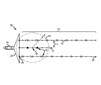
FIG. 1 is a schematic diagram of a representative seismic array 10, utilizing
an
advanced acoustic ranging network as described herein. In this particular
example, array
10 includes a plurality of individual seismic streamers or streamer cables 12,
towed
behind a seismic source boat or other vessel 14. Each towed streamer 12
includes a
¨3¨
Date recue/Date received 2023-06-05
series of hydrophones or acoustic receivers 16 (RX). A plurality of acoustic
transmitters
or transceivers 18 (TX) are distributed along one or more of the streamer
cables.
Streamers 12 are typically deployed using a combination of tow ropes, lead-in
cables and separation lines, or a similar tow apparatus 20. While five
individual
streamers (Si¨S5) are shown in FIG. 1, the number may vary (e.g., from one
streamer to
twelve streamers or more).
A towed air gun array or other seismic source system can also be provided,
along
with a computer-based control system 22 for coordinating seismic data
acquisition from
array 10, and to provide advanced positioning solutions for the acoustic
receivers 16 on
each streamer 12. System 30 includes an array 10 of such streamers 12, in
combination
with a processor or controller, e.g., computer-based navigational control
system 22 on
board tow vessel 14. Transmitter/interface 24 can provide for a combination of
wired
and wireless telemetry and other communications between controller 22 and
acoustic
receivers 16 on streamers 12, as well as the acoustic transmitters 18, the
seismic sources,
and the other elements of towed array 10. (See also, e.g., system 30 of FIGS.
2A ¨ 4B,
with an array 10 of such streamers 12 in combination with an air gun array or
other
seismic source(s) 32).Separation distances between acoustic
transmitter/receiver or
transceiver pairs can be determined by acoustic ranging. In one-way ranging,
transmitters 18 emit hydroacoustic pulses that travel through the water to
acoustic
receivers 16. The corresponding spatial separation is directly proportional to
the
propagation time, and indirectly proportional to the sound velocity in the
water (or other
medium). In two-way ranging, pulses are exchanged, and the separation is
determined
from the average propagation time.
Two-way ranging requires acoustic transceivers, rather than
transmmitter/receiver
pairs, but it reduces the need for close clock synchronization, since any
fixed timing
offset cancels out (at least to first order).
Signal processing time can also be
substantially increased, however, based on the number of pulses that are
exchanged, and
there is also more chance of confusion when multiple signals from different
sources
overlap in time.
Time division multiplexing can address some of these concerns, and the
acoustic
ranging pulses cart also be sent over different channels. But traditional
multiplexing
schemes can substantially increase the transmission scheduling time, and using
different
frequencies does not necessarily guarantee positioning accuracy, particularly
if the
ranging cycle takes so long that the array has moved substantially in the
meantime.
_4_
Date recue/Date received 2023-06-05
A more advanced approach can take a full range of possible acoustic network
geometries into account, in order to more effectively match the needs of a
particular
seismic array. The network geometries and signal exchange protocol can also be
more
closely coordinated, in order to provide faster and more accurate positioning
solutions,
adaptable to a wider variety of different seismic array configurations,
including
configuration that change in real time.
More generally, the acoustic ranging techniques described here provide a more
suitable acoustic network solution, based upon the full set of possible range
observations
that are available. Every potential range in the set is predefined and
preconfigured.
Using other known navigation references such as tail buoy position, streamer
layback,
course made good, etc., the real-time, in-water range observations can be
assigned to the
corresponding preconfigured ranges, in the predefined set.
No changes to the acoustic ranging configuration are necessarily required,
even
as the acoustic network changes shape. Applications thus include towed marine
seismic
arrays, where the streamer geometry is subject to changes due to wind, waves,
and
current effects, as well as changes during deployment, and due to navigation
of the array
by the towing vessel.
FIG. 2A is a diagram of an exemplary acoustic network and ranging system 30,
for example in a towed seismic array 10 with multiple (e.g., twelve) streamers
12.
Streamers 12 are towed by vessel 14, as described above. In this particular
configuration, an air gun array or other seismic source 32 is provided. Tow
apparatus 20
may also include additional elements, for example head floats 34 forward of
each
streamer 12, and trailing tail floats or tail buoys 36.
Acoustic system 30 includes an acoustic network made up of hydrophones or
other acoustic receivers 16 (shown as diamonds) and acoustic transmitters 18
(shown as
circles; neither is to scale). Acoustic receivers 16 are disposed at spaced
apart locations
along the length of streamers 12, and configured to receive the acoustic
signals generated
by acoustic transmitters 18. More particularly, each acoustic receiver 16 is
operated to
receive only acoustic signals from acoustic transmitters 18 within the
acoustic receiver's
16 predefined reception region or listening distance, in combination with a
corresponding limited receive time window for faster, more accurate acoustic
ranging, as
described herein.
Acoustic transceivers 16 or 18 can also be used, where individual acoustic
receivers 16 and acoustic transmitters 18 are distinguished by operation of
the
¨5¨
Date recue/Date received 2023-06-05
transceiver in either listening (reception) or broadcast (transmission) mode.
Individual
acoustic receivers 16 and acoustic transmitters 18 can also be physically
exchanged or
replaced, allowing acoustic network system 30 to take on a wide range of
different
configurations and geometries, as adapted to the particular requirements of
each seismic
array 10.
FIG. 2B is a diagram of acoustic ranging system 30 for an alternate seismic
array
10, with eight streamers 12 towed by vessel 14. FIG. 2B represents a
relatively less
dense seismic streamer configuration that that of FIG. 2B, with relatively
greater lateral
separation between individual acoustic receivers 16 on each streamer 12.
Acoustic transmitters 18 can be relatively sparsely spaced along streamers 12,
as
compared to acoustic receivers 16. Conversely, acoustic receivers 16 are
relatively
densely spaced, as compared to acoustic transmitters 18.
Suitable acoustic
receiver/transmitter ratios include, but are not limited to, about 5:1, as
shown in FIG. 2A,
and about 2:1, as shown in FIG. 2B. Alternatively, the acoustic
receiver/transmitter ratio
may vary, for example about 1:1 (e.g., in an acoustic transceiver
configuration), or from
about 2:1 or less to about 10:1 or more, depending upon the geometry of
seismic array
10, and the desired network configuration of acoustic ranging system 30.
Each acoustic transmitter 18 transmits acoustic ranging signals on one or more
of
N available channels (e.g., selected from among N=16 channels, or N=32
channels). The
different channels can be distinguished by frequency band, modulation, or
other suitable
coding (e.g., with a channel identifier embedded in each acoustic signal).
A
synchronization signal can also be provided (e.g., by controller 22), so that
all of the
active transmitters 18 send the acoustic signals at approximately the same
time. Thus, all
the acoustic signals in a particular ranging cycle will propagate
substantially
simultaneously through the water (or other medium).
The synchronization signal can also be used to trigger a predetermined time
window or other limited interval for signal reception, corresponding to the
propagation
time of an acoustic signal received by any of the acoustic receivers 16, from
an acoustic
transmitter 18 within the preselected listening distance or range. Other
acoustic signals
received outside the predefined interval may be ignored, as they fall outside
the limited
listening range.
Acoustic transmitters 18 can thus be configured to respond only to signals
received inside the predefined reception time window, or from within the
preselected
listening range, and to process only these signals for telemetry to the
controller. Signals
¨6¨
Date recue/Date received 2023-06-05
that are not received from within the predefined distance or listening
interval can be
excluded from the processing, and not included in the telemetry to the
controller.
Similarly, the processor can be configured to ignore any such signals in the
telemetry,
and determine the acoustic receiver/transmitter distances using only signals
from inside
the predefined interval, and within the preselected range. Thus, the
positioning solution
can be generated without any acoustic signals received from outside the
preselected
listening distance, that do not fall within the predefined signal receive
interval.
The preselected listening range and predefined reception time intervals can be
defined system wide, or on a receiver by receiver basis. For example,
predefined
listening ranges and corresponding reception time intervals can be globally
defined for
acoustic ranging system 30, or determined for individual acoustic receivers
16, or groups
of acoustic receivers 16, e.g., on a particular seismic streamer 12, or in a
selected portion
of seismic array 10.
In one particular example, all the acoustic transmitters 18 in seismic array
10
send a ranging pulse at substantially the same time (e.g., at t=tu), each
using one of the
selected channels. Alternatively, a selected subset of acoustic transmitters
18 can be
used, e.g., all acoustic transmitters 18 on one or more selected streamers 12
(e.g., the
middle streamer or middle two streamers 12 in array 10), or on alternating
even and odd-
indexed acoustic transmitters 18, or some other subset (e.g., in the front,
back, middle
and outside portions of array 10).
One or more of the acoustic receivers 16 are typically configured to respond
to
acoustic ranging signals transmitted on a selected subset of the available
channels, for
example on an even or odd subset representing eight of sixteen available
channels, or
sixteen of thirty-two, etc.. Additionally or alternatively, one or more of the
acoustic
receivers 16 can be configured to respond to any signal on any of the
available channels,
or to respond to signals on fewer than half of the channels.
The acoustic signals obtained by each acoustic receiver 16 are defined by the
acoustic signal amplitude and frequency, the layback position of the
corresponding
acoustic transmitters 18, and the time window allowed for acoustic signal
propagation
and reception (e.g., based on the known speed of sound in the water or other
medium).
Thus, a predetermined set of different (limited) listening ranges can be
defined for each
acoustic receiver 16, and acoustic transmitters 18 within the predefined
listening ranges
can be identified, based on the signal arrival time and selected channel.
Acoustic
receivers 16 can also be configured to respond only to signals from acoustic
transmitters
¨7¨
Date recue/Date received 2023-06-05
18 within the predefined range, for example by defining a limited time
interval over
which signals are processed (e.g., corresponding to the maximum propagation
time for
acoustic signals within the predefined range, as described above).
The navigational system on vessel 14 (or a control system 22, see FIG. 1)
knows
the layback distance of each acoustic receiver 16. More generally, a complete
layback
diagram can be stored in computer memory, including laybacks for acoustic
receivers 16
and acoustic transmitters 18, seismic sources 32, head floats 34, tail buoys
36, the source
and streamer towpoints, and other relevant geometry for towed array 10.
Ranges are made up by determining the nearest acoustic transmitter (TX) to
receiver (RX) distance, where each acoustic receiver 16 can use information
from the
acoustic ranging signal (e.g., including arrival time and transmission
channel) to identify
the nearest acoustic transmitters 18. Additional acoustic transmitters 18 can
also be
identified, if the ranging signal is sent on an appropriate channel, and
arrives within a
predefined time interval, from within the predefined listening distance.
Following the synchronization signal, acoustic receivers 16 may thus perform
acoustic reception and data processing functions only during the predefined
time interval
(or receive window). The receive interval corresponds to the transit (or
propagation)
time of an acoustic signal from an acoustic transmitter located at the outer
boundary or
limit of each acoustic receiver's reception region (or listening range). At
the end of the
receive window, the acoustic reception and/or processing functions are
terminated, and
signals received after the predefined interval are not necessarily processed
or included in
the telemetry (or other communications with the navigational/ranging
controller).
Alternatively, the controller can also accept any such data but calculate the
positioning
solution without it, using only signals received from within the preselected
listening
range and within the predefined time window, as described above, absent any
acoustic
signals from outside the listening range or reception window.
FIG. 3A is an illustration of a representative range ring 40 for acoustic
network
and ranging system 30, with limited range or listening distance D. In this
example,
listening distance D is defined for a relatively dense towed seismic array 10,
with
relatively low lateral separation between streamers 12 (e.g., as shown in FIG.
2A,
above).
The listening range is defined at least in part by determining the nearest
acoustic
transmitter 18 to each acoustic receiver 16. Generally, listening distance or
range D
should include at least one or more actively broadcasting acoustic
transmitters 18, for
¨8¨
Date recue/Date received 2023-06-05
each acoustic receiver 16 on an active streamer 12. At the same time,
listening distance
D can also be limited to reduce the number of acoustic transmitters 18
broadcasting on
the same channel, within "hearing" of a particular acoustic receiver 16.
For example, the listening range can be limited so that there is only one
acoustic
transmitter 18 on each available channel within distance D, or no more than
one such
acoustic transmitter 18 that broadcasts on each channel or frequency to which
each
acoustic transmitter 18 responds. As shown in FIG. 3A, for example, the
limited range
defines a subset of fourteen individual acoustic transmitters 18, each of
which is
disposed within distance D of a representative acoustic receiver 16.
Each of the fourteen acoustic transmitters 18 within listening distance D of
the
selected acoustic receiver 16 broadcasts on a different one of the N=16
available
channels, some of which are even, and some of which are odd. Thus, the
selected
acoustic receiver 16 will typically receive seven acoustic signals within the
predefined
interval, whether it has even or odd polarity (for example, either seven odd
channels
selected from c I , c3, c5, c9, c7, c I 1, cI3 and c15, or seven even channels
selected from
c2, c4, c6, c8, c10, c12, c14 and c16).
More generally, a suitable range (radius or distance) D can be selected to
include
a subset of acoustic transmitters 18 operating on at least one and typically
one quarter to
one half or more of the number of available channels N. Suitable listening
distances D
are also selected to include no more than one acoustic transmitter 18 on each
channel to
which a given acoustic transmitter responds. Thus, the subset of transmitters
18 defined
by each limited range or reception region will typically number at least one
or more, but
less than or equal to the total number of available channels N.
FIG. 3B is an illustration of an alternate range ring 40 for acoustic network
or
ranging system 30. In this example, the limited range (or listening distance)
D is defined
for a relatively less dense towed seismic array 10, with relatively greater
lateral
separation between individual streamers 12 (e.g., as shown in FIG. 2B).
As shown in FIG. 3B, suitable listening ranges D vary not only with the
density
of streamers 12, but also depending on the density of acoustic transmitters
18, based on
the number and layback of acoustic transmitters 18 along each individual
streamer 12.
The navigation/ranging control system knows the layback of the acoustic
receivers 16
and acoustic transmitters 18, as described above. Thus, based on the limited
listening
range of each acoustic receiver 16 and the acoustic transmitter laybacks,
listening
distance D can be reduced for denser acoustic transmitter configurations, and
increased
¨9¨
Date recue/Date received 2023-06-05
for less dense acoustic transmitter configurations, in order to maintain a
suitable number
of acoustic transmitters 18 within the listening distance of each acoustic
receiver 16,
regardless of stringer and array geometry.
The in-water cycle time necessary to complete a positioning solution depends,
inter alia, upon the maximum signal propagation time, over the signal
reception time
window. in one-way ranging, for example, an initial synchronization signal may
be
transmitted, followed by hydroacoustic ranging signals from individual
acoustic
transmitters 18 on all the available channels. With an estimated sound speed
of about
1500 m/s in seawater, and for a listening range limited to D<1,000 m (1 km),
the nominal
propagation time is less than about 0.7 s. For a listening range limited to
D<600 m (0.6
km), the nominal propagation time is about 0.4 seconds, or less. If all the
acoustic
signals are transmitted at substantially the same time, this defines the cycle
time for
obtaining acoustic ranging data, from which a positioning solution can be
derived.
Depending upon array geometry, including streamer lateral separation and
acoustic transmitter layback, other suitable listening range limits may vary
from about
D=100 m (0.1 km) or less for smaller or more densely populated arrays, to
about
D=2,000 m (2 km) or more for larger and less densely populated arrays.
Alternatively,
suitable listening ranges may vary up to D=5,000 in (5 km) or more, for very
large,
sparsely populated arrays. The corresponding receive time windows range from
less
than a tenth of a second up to a few seconds or more.
Generally, channels are assigned to acoustic transmitters 18 so that no two
transmitters operate on the same channel, within a particular separation
distance. For
suitable listening distances, this allows for subsets of the acoustic
transmitters to operate
on different channels within the preselected range of a particular acoustic
receiver 16,
while preventing acoustic transmitters 18 from operating on the same channel,
when
within the listening range of any one particular (same) acoustic receiver 16.
Acoustic
transmitters 18 in exclusive subsets, however, can transmit on the same
channel, where
they are not operating within the listening range of the same acoustic
receiver 16.
The broadcast channels for laterally oriented acoustic transmitters 18 can
also be
indexed in series, for example across alternating streamers 12 as shown in
FIG. 3B, or
staggered across a number of laterally adjacent streamers 12, as shown in FIG.
3A. In
these configurations, only about half of the in-range acoustic transmitters 18
are typically
broadcasting on odd channels, and about half are broadcasting on even
channels, as
described above.
¨10¨
Date recue/Date received 2023-06-05
Selective channel response thus reduces the number of observable ranging
signals, for each acoustic receiver 16. Alternatively, acoustic receivers 16
could be
modified to listen for signals on both even and odd channels, so that they
respond to all
acoustic transmitters 18 within range. The timing synchronization signal could
also
include a counter or indexing signal, used to determine the channel response
for
individual acoustic receivers 16, in each acoustic ranging cycle. Thus,
acoustic receivers
16 could also be configured to respond to different sets of in-range acoustic
transmitters 18 in successive ranging operations, e.g., alternating between
even and odd
channels, or cycling sequentially through channels, in order to provide a
different basis
for successive ranging operations. This approach can improve redundancy in the
positioning solution, increasing the number of potential observations by a
factor of up to
ten or more, and increasing accuracy and reliability in the corresponding
acoustic
receiver/transmitter separations.
FIG. 4A is a diagram illustrating a representative range ring 40 for acoustic
receiver 16 on seismic cable streamer 12, shown in deployment within the
middle
position or inner region of towed seismic array 10, between laterally outer
streamer
cables 12. In this particular example, middle streamer cable 12 is being
deployed by tow
vessel 14, e.g., utilizing a tow apparatus 20 as described above.
FIG. 4B is a diagram illustrating range ring 40 for acoustic receiver 16 on
streamer cable 12, shown in deployment within the middle position or inner
region of an
alternate seismic array 10. As shown in FIG. 4B, the listening distance for
acoustic
receiver 16 is defined with a relatively higher limited range D, as compared
to FIG. 4A,
corresponding to the relatively higher lateral spacing L of streamers 12.
Hydroacoustic ranging system 30 thus provides an improved acoustic network
solution, based upon the range observations available at a variety of
different listening
distances, regardless of the current geometry of seismic array 10. Each
possible or
potential distance D can be predefined by system 30, and real-time, in-water
range
observations can be assigned to the preconfigured ranges using other known
navigation
references such as tail buoy position, streamer layback, and course made good.
No
changes in the ranging configuration are required as the acoustic network
change shape,
whether due to wind, waves, currents or navigational effects, or during
streamer
deployment, as shown in FIGS. 4A and 4B.
As another example, the controller could execute an algorithm that uses
positioning data and streamer configuration data (e.g., layback diagram data
stored in
¨11¨
Date recue/Date received 2023-06-05
memory plus real-time streamer navigational data) to determine which acoustic
transmitters 18 reside within (or are disposed in) the reception region or
listening
distance D of each respective acoustic receiver 16. The controller could also
assign each
acoustic receiver 16 to activate only those channels assigned to the acoustic
transmitters
18 expected to be within the listening range. As these examples suggest, other
possibilities are also included and the spirit and scope of the invention is
not to be
limited to the particular description of the various versions that are
disclosed as examples
herein, except as defined by the language of the claims themselves.
Now turning to FIG. 5, a computer processor or controller 50 can be configured
to define a limited listening distance or range for each acoustic receiver.
For example, a
ranging controller 50 can be used to exchange telemetry and other data with
the acoustic
transmitters and receivers, including memory for storing a layback diagram
describing
the acoustic transmitter and receiver positions along the streamers, in
combination with
navigational data describing tow positions, buoy and float positions, course
made good,
etc.
FIG. 5 is a schematic diagram of a controller 50 that can be implemented in an
acoustic networking ranging system 30. As shown in FIG. 5, controller 50
includes one
or more processors 51, sensors 52, memory components 53, power sources 54,
displays
55, interfaces 56, and input/output devices 57. In some embodiments, the
controller 50
comprises or is comprised within a navigational controller 22, as represented
in FIG. 1.
The one or more electronic processors 51 utilized by controller 50 are
configured
for processing, receiving, and/or transmitting instructions for acoustic
ranging
applications, as described herein. For example, individual processors 51
typically
include microprocessor or microcomputer components executing software code
stored on
non-transitory computer-readable media, where the code is executed according
to the
acoustic ranging techniques described herein.
The processor 51 may include more than one individual processing component.
For example, a first processing element 51 may control a first set of
components 52-57
of the controller system 50, and one or more second and other processing
elements 51
may control other sets of the controller components 52-57. The processing
elements 51
can operate independently or in coordinated fashion, and may or may not
communicate
data and instructions with one another. Additionally, each processor 51 can be
configured to execute instructions in series or in parallel. The individual
processors 51
and other selected elements 52-57 of controller 50 may also be distributed
along the
¨12¨
Date recue/Date received 2023-06-05
streamer or seismic cable components, for example among the acoustic
receivers,
transmitters and/or transceivers, or on another elements such as a head float
or tail buoy.
In some applications, controller 50 can also utilize one or more cloud-based
processors
51 and other components 52-57, utilizing a combination of hard-wired,
acoustic, and
wireless links for communication.
The one or more sensors 52 can be adapted provide substantially any type of
suitable input to controller 50. The type, number, and location of the one or
more sensor
52 may also vary as desired, depending on the desired functions of the
acoustic ranging
system for which controller 50 is adapted. For example, sensors 52 may include
acoustic
receivers and transceivers and other seismic survey system components, as
described
herein.
Memory 53 stores electronic data utilized by the controller 50. For example,
the
memory 53 may store data in electronic or magnetic form, or using other data
storage
techniques. The memory 53 may include, for example, non-volatile or non-
transitory
machine-readable data storage components, volatile or transitory storage
components, a
magnetic storage medium, optical storage medium, magneto-optical storage
medium,
read only memory, random access memory, erasable programmable memory, flash
memory, or a combination thereof.
Display 55 provides a visual output for the controller 50. The display 55 may
be
configured with any suitable size and can be positioned substantially anywhere
on or
within the controller apparatus 50. In some embodiments, display 55 is
interactive, and
on other embodiment controller 50 does not necessarily include a display 55.
Data interface 56 transmits and receives data being communicated with the
controller 50. In some embodiments, data interface 56 comprises or is
comprised within
an interface 24 in communication with a navigational system, as shown in FIG.
I . The
data interface 56 may transmit data to and receive data from an acoustic
ranging
network, as described herein, including acoustic receivers 16 and/or
transmitters 18
distributed along a seismic cable or streamer, and/or other computing devices.
For
example, suitable data interfaces 56 may transmit data to and from other
computing
devices through a wireless network (e.g., acoustic, optical, WiFi, Bluetooth,
cellular
network, etc.), or a wired network (e.g., Ethernet or other dedicated network
system), or
using a combination thereof. As a specific example, one or more data
interfaces 56 can
be configured to allow a suitable controller 50 to communicate with acoustic
receivers 16
and/or transmitters 18 for coordinating acoustic ranging and seismic data
acquisition for
¨13¨
Date recue/Date received 2023-06-05
a number of streamers 12 or other seismic array 10, as described herein. Data
interface
56 may also translate messages, instructions and other data for the controller
50, using a
format that adapted for the acoustic receivers 16 and/or transmitters 18 to
transmit and
receive.
Input/output (I/0) interface 58 allows the controller 50 to receive input from
and
provide output to a user or external control system. For example, I/0
interface 56 may
include a keyboard, touch screen, mouse, stylus, or the like, with or without
a display 55.
The configuration of the devices that interact via I/O interface 58 may be
varied as
desired, depending upon application. In some embodiments, the controller 50
does not
necessarily include distinct display 55 and I/O interface components 58.
Controller 50 also includes a power source 54, in order to provide power to
the
various other controller components 51-53 and 55-57. The power source 54 may
include one or more rechargeable, disposable, or hardwire sources, e.g.,
batteries, line
power, power supplies, or the like. Additionally, suitable power sources 54
may include
one or more adapters, connectors or similar elements that provide different
types of
power to the various components of controller 50. In some embodiments, the
power
source 54 is adapted for use with a serial bus or similar connections that
provide power
to the various controller components, and can also transmit data and
instructions for
communication via I/0 interface 58, and for communication to and from the
acoustic
receivers 16, transmitters 18 and other components of a seismic cable or
seismic array
via data interface 56.
The components of the controller 50 can also be distributed over such an array
10, as described above, e.g., distributed among the acoustic receivers 16
and/or
transmitters 18, and/or using one or more remote network or cloud-based
processor
components in communication with controller 50 via interface 56.
FIG. 6 is a flow chart illustrating a method 60 for determining acoustic
ranges
between acoustic receivers and selected acoustic transmitters. As shown in
FIG. 6,
method 60 includes one or more steps of towing or otherwise deploying a
streamer or
other seismic cable (step 62), generating signals with one or more acoustic
transmitters
or receivers (step 64), defining a range or "listening distance" for the
acoustic receivers
(step 66), and deterring acoustic ranges between the transmitters and
receivers based on
the acoustic signals (step 68).
In step 62 (towing or deployment), a plurality of streamer cables 12 having a
plurality of acoustic receivers are deployed and towed in order to conduct a
seismic
¨14¨
Date recue/Date received 2023-06-05
survey, for example by a seismic vessel 14 as describe herein. More generally,
suitable
acoustic receivers, transmitters and/or transceiver components can be deployed
along any
suitable seismic cable, or along a set of seismic cables in a seismic array.
In step 64 (signal generation), acoustic signals are generated by a plurality
of
acoustic transmitters 18 spaced along one or more of the streamers 12. The
acoustic
receivers and transmitters can either be provided as distinct components, or
in the form
of acoustic transceivers.
In step 66, a limited listening distance is defined for each acoustic receiver
16, in
which the acoustic signals are received from selected acoustic transmitters 18
within a
defined listening distance. The listening distance can also be described as a
signal
acquisition limit, where signals generated within the defined distance of a
particular
acoustic receiver or transceiver are included, and utilized for ranging, while
signals
generated outside the defined distance are excluded, and not utilized for
ranging.
In step 68, a controller 22 or 50 determines the acoustic ranges between the
acoustic receivers 16 and the acoustic transmitters 18, based on the acoustic
signals from
the selected acoustic transmitters 18. For example, the acoustic ranges may be
determined based only on the acoustic signals received from the selected
acoustic
transmitters within the limited listening distance, which are included in the
ranging
analysis, absent acoustic signals received from outside the listening
distance, which are
excluded from the ranging analysis.
The acoustic ranges can also be are determined based only on the acoustic
signals
received within a time window defined for propagation of the acoustic signals
over the
limited listening distance, absent acoustic signals received outside the time
widow. A
synchronizing signal can be generated for each of the acoustic transmitters,
in order to
generate the acoustic signals in the same, network-wide transmission interval,
where the
acoustic signals from different transmitters propagate substantially
simultaneously over
the limited listening distance. Different channels can also be assigned to
each of the
selected acoustic transmitters or transceivers within the limited listening
distance, where
the selected acoustic components transmit the acoustic signals over the
different
channels.
EXAMPLES
An acoustic ranging system may include a plurality of streamers and a
plurality
of acoustic receivers disposed along the streamers, each acoustic receiver
configured to
receive acoustic signals, e.g., for seismic data acquisition and acoustic
ranging. A
¨15¨
Date recue/Date received 2023-06-05
plurality of acoustic transmitters can be disposed along one or more of the
streamers,
each acoustic transmitter configured to generate the acoustic signals over one
or more of
a plurality of available channels.
A computer processor or controller can be configured to define a limited
listening
distance or range for each acoustic receiver. For example, a ranging
controller can be
used to exchange telemetry and other data with the acoustic transmitters and
receivers,
including memory for storing a layback diagram describing the acoustic
transmitter and
receiver positions along the streamers, in combination with navigational data
describing
tow positions, buoy and float positions, course made good information, and
other
navigational and positional data for the array of streamers.
A subset of the acoustic transmitters can be defined within the limited range,
where each acoustic transmitter in the subset is configured to generate the
acoustic
signals over a different one of the channels. The acoustic receivers can then
be
configured to respond only to signals received from acoustic transmitters
within the
limited range.
For example, the processor can be configured to generate a positioning
solution
for the streamers based only on the acoustic signals received by each acoustic
receiver
from the corresponding subset of acoustic transmitters, within the limited
range or
listening distance. Similarly, the processor can determine acoustic ranges
between each
of the acoustic receivers and selected acoustic transmitters in the
corresponding subsets,
based only on the acoustic signals received by the acoustic receivers from an
acoustic
transmitter within the limited distance thereof. Thus, the acoustic ranges can
be
determined without or absent of any acoustic signals received from acoustic
transmitters
that are outside the preselected range.
In any of the above examples and embodiments, the acoustic transmitters can be
configured to generate the acoustic signals over the same transmission
interval, e.g.,
using a synchronization pulse generated by the controller. Thus, the acoustic
ranging
cycle time of the system can be substantially determined by the propagation of
the
acoustic signals over the limited range. For example, the limited range or
preselected
range can be defined based on either the lateral spacing of the streamers, the
layback of
the acoustic transmitters, or both. The limited distance can also define each
of the
subsets with acoustic transmitters generating the acoustic signals over
different channels,
while acoustic transmitters in exclusive subsets generate the acoustic signals
over at least
one same channel.
¨16¨
Date recue/Date received 2023-06-05
In any of the above examples and embodiments, the acoustic receivers can be
configured to process only acoustic signals received over a limited time
interval
corresponding to propagation of the acoustic signals over the limited range.
Each of the
acoustic receivers can be configured for receiving the acoustic signals
generated in any
of the channels, or to process only the acoustic signals received over
channels assigned
to acoustic transmitters within the limited range.
In method embodiments, a plurality of streamers or seismic cables can be
deployed in a seismic array, e.g., towed behind a seismic source boat or other
vessel.
Each cable includes a plurality of acoustic receivers spaced along the cable
length.
Acoustic signals are generated with a plurality of acoustic transmitters,
which are spaced
along one or more of the cables.
A limited range or listening distance is defined for each acoustic receiver,
where
the acoustic signals are received from selected acoustic transmitters within
the listening
distance. Acoustic ranges are determined between the acoustic receivers and
the selected
acoustic transmitters, based on the propagation time of the acoustic signals
from the
selected acoustic transmitters to the acoustic receivers, within the listening
distance.
In any of the above examples and embodiments, the acoustic ranges can be based
only on the acoustic signals received from the selected acoustic transmitters
within the
listening distance, absent acoustic signals received from outside the
listening distance.
Similarly, the acoustic ranges can also be determined based only on the
acoustic signals
received within a time window defined for propagation of the acoustic signals
over the
listening distance, absent acoustic signals received outside the time widow.
In any of the above examples and embodiments, a synchronizing signal can be
generated for each of the acoustic transmitters, e.g., via telemetry or using
a wireless
signal from the acoustic ranging controller. The synchronizing signal can be
configured
to trigger the acoustic transmitters to generate the acoustic signals in the
same
transmission interval, so the acoustic signals from different transmitters
propagate
substantially simultaneously over the listening distance. Different channels
can be
assigned to each of the selected acoustic transmitters within the listening
distance, where
the selected acoustic transmitters transmit the acoustic signals over the
different
channels.
In any of the above examples and embodiments, a minimum separation can be
defined between acoustic transmitters assigned to the same channel, where any
acoustic
transmitters within the minimum separation of one another are assigned
different
¨17¨
Date recue/Date received 2023-06-05
channels. Thus, only acoustic transmitters outside the minimum separation from
one
another may be assigned to the same channel.
Ranging system embodiments include a plurality of towed streamers or other
seismic cables, e.g., in a marine seismic array. A plurality of receivers is
disposed along
the towed streamers, each receiver configured to receive ranging signals. A
plurality of
transmitters is disposed along one or more of the streamers, each transmitter
configured
to generate the ranging signals over one or more selected channels.
A processor or computer-based ranging controller is configured to determine
distances between the receivers and the transmitters, based on propagation of
the ranging
signals from the transmitters within a limited range of each receiver. Each
transmitter
within the limited range is configured to generate the ranging signals over a
different one
of the selected channels, and the distances between the receivers and
transmitters can be
determined based only on the ranging signals received within a time interval
defined by
propagation of the signals over the limited range, absent any signals received
from
transmitters outside the time interval. In seismic array applications, the
limited range can
be based on lateral spacing of the streamers, the layback of the transmitters,
or both.
In any of the above examples and embodiments, the processor or controller can
be configured to generate a synchronization signal, in order for the
transmitters to
generate the ranging signals at approximately the same time, so that the
signals
propagate substantially simultaneously over the limited range. The
synchronization
signal can also be configured for the receivers to process the ranging signals
received
over different channels on successive transmissions thereof, where the
distances on the
successive transmissions are determined between the receivers and the
transmitters
configured to generate the ranging signals over the different channels.
More specifically, a system is disclosed comprising a plurality of streamers,
a
plurality of acoustic receivers disposed along the streamers, each configured
to receive
acoustic signals, and a plurality of acoustic transmitters disposed along one
or more of
the streamers, each configured to generate the acoustic signals over one or
more of a
plurality of channels. A processor is configured to define a limited range for
each
acoustic receiver, where a subset of the acoustic transmitters is defined
within the limited
range thereof, and where each acoustic transmitter in the subset is configured
to generate
the acoustic signals over a different one of the channels.
In some embodiments, the processor is further configured to generate a
positioning solution based only on the acoustic signals received by each
acoustic receiver
¨18¨
Date recue/Date received 2023-06-05
from the corresponding subset of acoustic transmitters within the limited
range. In
particular examples, the processor is configured to determine acoustic ranges
between
each acoustic receiver and selected acoustic transmitters in the corresponding
subsets,
based only on the acoustic signals received by the acoustic receivers from an
acoustic
transmitter within the limited range thereof.
In any of these examples and embodiments, the acoustic ranges can determined
absent acoustic signals received from acoustic transmitters outside the
limited range.
Depending on application, the acoustic transmitters can be configured to
generate the
acoustic signals over a same transmission interval, such that an acoustic
ranging cycle
time of the system is substantially determined by propagation of the acoustic
signals over
the limited range.
The limited range can be defined based on at least one of lateral spacing of
the
streamers or a layback of the acoustic transmitters. In particular examples,
the limited
range defines each of the subsets with acoustic transmitters generating the
acoustic
signals over different channels, where acoustic transmitters in exclusive
subsets generate
the acoustic signals over at least one same channel.
In any of these examples and embodiments, the acoustic receivers can be
configured to process only acoustic signals received over a time interval
corresponding
to propagation of the acoustic signals over the limited range. In particular
examples,
each of the acoustic receivers is configured for receiving the acoustic
signals generated
in any of the channels. In additional examples, the acoustic receivers are
further
configured to process only the acoustic signals received over channels
assigned to
acoustic transmitters within the limited range.
A method is disclosed comprising the steps of towing a plurality of streamer
cables, each streamer cable having a plurality of acoustic receivers spaced
along a length
thereof, generating acoustic signals with a plurality of acoustic transmitters
spaced along
one or more of the streamer cables, and defining a limited listening distance
for each
acoustic receiver, where the acoustic signals are received from selected
acoustic
transmitters within the listening distance. Acoustic ranges are determined
between the
acoustic receivers and the selected acoustic transmitters based on propagation
time of the
acoustic signals from the selected acoustic transmitters to the acoustic
receivers, within
the listening distance.
In some embodiments, the acoustic ranges are based only on the acoustic
signals
received from the selected acoustic transmitters within the limited listening
distance,
¨19¨
Date recue/Date received 2023-06-05
absent acoustic signals received from outside the listening distance. In
particular
examples, the acoustic ranges are determined based only on the acoustic
signals received
within a time window defined for propagation of the acoustic signals over the
limited
listening distance, absent acoustic signals received outside the time widow.
In any of these examples and embodiments, the method may further include
generating a synchronizing signal for each of the acoustic transmitters to
generate the
acoustic signals in a same transmission interval, where the acoustic signals
from different
transmitters propagate substantially simultaneously over the limited listening
distance. In
particular examples, the method further includes assigning different channels
to each of
the selected acoustic transmitters within the limited listening distance,
where the selected
acoustic transmitters transmit the acoustic signals over the different
channels. In
additional examples, the method further includes defining a minimum separation
between acoustic transmitters assigned to a same channel, where any acoustic
transmitters within the minimum separation of one another are assigned to
different
channels, and only acoustic transmitters outside the minimum separation from
one
another are assigned to the same channel.
A ranging system is also disclosed. The ranging system includes a plurality of
towed streamers, a plurality of receivers disposed along the towed streamers,
each
configured to receive ranging signals, and a plurality of transmitters
disposed along one
or more of the streamers, each configured to generate the ranging signals over
one or
more selected channels. A processor or controller is configured to determine
distances
between the receivers and the transmitters based on propagation of the ranging
signals
from the transmitters within a limited range of each receiver, where each
transmitter
within the limited range is configured to generate the ranging signals over a
different one
of the selected channels.
In any of these examples and embodiments, the distances between the receivers
and the transmitters can be determined based only on the ranging signals
received within
a time interval defined by propagation of the ranging signals over the limited
range,
absent any ranging signals received outside the time interval. In particular
examples, the
limited range is based on one or more of a lateral spacing of the streamers
and a layback
of the transmitters, and further comprising the processor configured to
generate a
synchronization signal for the transmitters, such that the ranging signals
propagate
substantially simultaneously over the limited range. In additional examples,
the
synchronization signal can be configured for the receivers to process the
ranging signals
¨20¨
Date recue/Date received 2023-06-05
received over different channels on successive transmissions thereof, such
that the
distances are determined on the successive transmission between the receivers
and the
transmitters configured to generate the ranging signals over the different
channels.
While this invention has been described with reference to exemplary
embodiments, it will be understood by those skilled in the art that various
changes can be
made and equivalents may be substituted without departing from the spirit and
scope
thereof. Modifications may also be made to adapt these teachings to other
applications
and to particular problems, technologies, and materials, without departing
from the
essential scope thereof. The invention is thus not limited to the particular
examples that
are disclosed, but encompasses all embodiments falling within the scope of the
appended
claims.
¨21¨
Date recue/Date received 2023-06-05