Note: Descriptions are shown in the official language in which they were submitted.
METHOD AND SYSTEM FOR DETECTING AND ACCOMMODATING LOSS OF A TORQUE
SIGNAL
TECHNICAL FIELD
[0001] The present disclosure relates generally to engine control, and, more
particularly, to
detecting and accommodating for loss of a torque signal.
BACKGROUND OF THE ART
[0002] Turboshaft and turboprop engines for aircraft often use a torque signal
for governing
either on torque or on power. In the unlikely event that the torque signal is
lost, it is desirable for
engine control systems to be designed so that engine control is maintained.
The loss of the
toque signal could be temporary or permanent and may be the result of a sensor
malfunction,
physical damage or electrical signal interruptions. Moreover, in some engine
hardware
configurations the torque signal of the system can be sensitive to aircraft
maneuvers.
[0003] As such, there is a need for improved systems and methods for detecting
and
accommodating for loss of a torque signal.
SUMMARY
[0004] In one aspect, there is provided a method for accommodating loss of a
torque signal of a
gas turbine engine. The method comprises determining an engine deterioration
offset while the
torque signal of the engine is available; determining a predicted operating
offset when the
torque signal is lost; and generating a synthesized torque signal when the
torque signal is lost at
least in part from the engine deterioration offset and the predicted operating
offset.
[0005] In another aspect, there is provided a system for accommodate for loss
of a torque
signal of a gas turbine engine. The system comprises at least one processing
unit and a non-
transitory computer-readable memory having stored thereon program instructions
executable by
the at least one processing unit. The program instructions are executable by
the at least one
processing unit for determining an engine deterioration offset while the
torque signal of the
engine is available; determining a predicted operating offset when the torque
signal is lost; and
generating a synthesized torque signal when the torque signal is lost at least
in part from the
engine deterioration offset and the predicted operating offset.
1
CA 3001209 2018-04-11
DESCRIPTION OF THE DRAWINGS
[0006] Reference is now made to the accompanying figures in which:
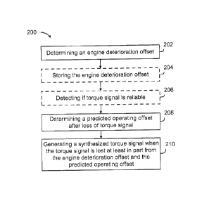
[0007] Figure 1 is a schematic cross-sectional view of an example engine of an
aircraft;
[0008] Figure 2 is a flowchart illustrating an example method for
accommodating loss of a
torque signal of an engine in accordance with an embodiment;
[0009] Figure 3 is an example graphical representation of a baseline
anticipation curve;
[0010] Figure 4 is an example graphical representation of an adjusted
anticipation curve offset
from the baseline anticipation curve of Figure 3 by an engine rotational speed
offset;
[0011] Figure 5 is an example graphical representation of an adjusted
anticipation curve offset
from the baseline anticipation curve of Figure 3 by an actual operating
offset;
[0012] Figure 6 is an example graphical representation showing an engine
deterioration offset
determined from the engine rotational speed offset of Figure 4 and the actual
operating offset of
Figure 5;
[0013] Figure 7 is an example graphical representation showing a predicted
operating offset
determined from the baseline anticipation curve of Figure 3;
[0014] Figure 8 is a graphical representation showing an adjusted anticipation
curve determined
from the predicted operating offset of Figure 7 and the engine deterioration
offset of Figure 6;
and
[0015] Figure 9 is a schematic diagram of an example computing system for
implementing the
method of Figure 2 in accordance with an embodiment.
[0016] It will be noted that throughout the appended drawings, like features
are identified by like
reference numerals.
DETAILED DESCRIPTION
[0017] Figure 1 illustrates a gas turbine engine 10 for which loss of a torque
signal may be
detected and accommodated for using the systems and methods described herein.
Engine 10
generally comprises in serial flow communication a propeller 120 attached to a
shaft 108 and
2
CA 3001209 2018-04-11
through which ambient air is propelled, a compressor section 114 for
pressurizing the air, a
combustor 116 in which the compressed air is mixed with fuel and ignited for
generating an
annular stream of hot combustion gases, and a turbine section 106 for
extracting energy from
the combustion gases.
[0018] A control system 50 is used to control operation of engine 10. The
control system 50
may be configured to receive one or more operational parameter signals
regarding operation of
the engine 10. The operational parameter signals may, for example, be from one
or more
sensors (not illustrated) associated with the engine 10. In accordance with an
embodiment, an
operational parameter signal comprises a torque of the engine 10. The control
system 50 may
be configured to send one or more control signals to the engine 10 to control
the operation of
the engine 10. In accordance with an embodiment, a control signal comprises a
power setting to
set the engine 10 at a specific power under specific ambient and extraction
conditions. The
control system 50 may implement one or more power setting functions to perform
various
calculations and/or operations relating to the engine 10. While the control
system 50 is
illustrated outside of the engine, this is for illustration purposes only ¨
the control system 50 may
be internal or external to the engine 10. In a specific and non-limiting
example of
implementation, the control system 50 may be implemented in an inner gas
generator control
loop of the engine 10. In another specific and non-limiting example of
implementation, the
control system 50 may be implemented in an electronic engine controller (EEC)
that is part of a
full authority digital engine (or electronics) control (FADEC).
[0019] With reference to Figure 2, there is shown a flowchart illustrating an
example method
200 for accommodating loss of a torque signal of the engine 10. The method 200
may be
implemented by the control system 50 associated with the engine 10.
[0020] At step 202, the control system 50 determines an engine deterioration
offset
(deltaNG_det) while the torque signal of the engine 10 is available. While
deltaNG_det is mainly
comprised of engine deterioration, in general, deltaNG_det corresponds to a
sum of engine
deterioration, engine production variability, engine model alignment,
installation effects (e.g.,
outside expectations, etc.), variability (e.g., aircraft to aircraft
variability, manufacturing
variability, installation variability, etc.) and installation efficiency
deterioration or damage (e.g.,
dirt, foreign object damage, etc.). It may represent the offset in fuel flow
applied by the control
system 50 to meet the power demands in a specific operating condition.
DeltaNG_det may be
determined by deriving a difference between an engine rotational speed offset
(deltaNG(PI))
3
CA 3001209 2018-04-11
and an actual operating offset (deltaNG_rat) while the torque signal of the
engine is available.
For instance, the following equation may be used to determine deltaNG_det:
deltaNG_det = deltaNG(PI) - deltaNG_rat (Equation 1).
[0021] With additional reference to Figure 3, an example of a baseline de-
normalized
anticipation curve 302 is illustrated, where the x-axis corresponds to engine
rotational speed
(NG) and the y-axis corresponds to engine power (SHP). Thus, the baseline de-
normalized
anticipation curve 302 defines a relationship between SHP and NG of the engine
10 at specific
ambient conditions. Anticipation curves of the type shown in Figure 3 may be
used in the case
of a torque failure as a baseline to govern control of the engine 10 based on
a derived torque.
[0022] While the baseline anticipation curve 302 may be modeled to
theoretically correspond
with the engine 10, due to various factors such as operating conditions of the
engine 10 and/or
aircraft selected operations, it should be appreciated that during operation,
the engine 10
delivered power schedule may not directly correspond with the anticipation
curve 302.
[0023] With additional reference to Figure 4, an example of a first adjusted
anticipation curve
301 is shown offset from the baseline anticipation curve 302 by deltaNG(PI)
300. As further
shown, a marker 305 illustrates a reference speed of rotation, a marker 303
illustrates an actual
NG, and a marker 304 illustrates an actual delivered power of the engine 10.
The reference
speed of rotation 305 corresponds to an expected rotational speed of the
engine 10 for the
actual delivered power 304 of the engine 10. During steady state operation of
the engine 10, an
error may occur between the reference (or expected) rotational speed 305 of
the engine 10 and
the actual NG 303 required of the engine 10. Accordingly, an error between the
anticipation
curve 302 at the reference speed of rotation 305 and the actual NG 303 may be
computed to
determine deltaNG(PI) 300. In particular, deltaNG(PI) 300 may be determined
from a difference
between the reference speed of rotation 305 of the engine 10 from the baseline
anticipation
curve 302 for the actual delivered power 304 of the engine 10 and the actual
NG 303 of the
engine 10 for the actual delivered power 304 of the engine 10. More
specifically, while the
torque signal is valid and the engine 10 is governed in a steady state
operation, the torque
signal may be used to determine the actual delivered power 304 of the engine
10. Then, the
actual NG 303 may be compared with the reference NG 305 from the baseline
anticipation
curve 302 to determine deltaNG(PI) 300 at the actual engine power 304.
4
CA 3001209 2018-04-11
[0024] DeltaNG(PI) 300 may be determined on a regular or irregular interval as
it may vary with
time. The interval for determining deltaNG(PI) 300 may be set to any suitable
interval (e.g.,
daily, hourly, every minute, etc.) while the engine 10 is in a steady state
operation. In general,
steady state operation of the engine 10 refers to: all parameters of the
engine 10 being stable,
such as, fuel flow, engine temperature, engine rotational speed, torque, etc.;
there being no pilot
input to change the conditions of the engine 10; constant extractions, such
as, bleed, load, etc.;
and constant ambient conditions, such as, altitude, air temperature, etc.
[0025] With reference to Figure 5, an example of a second adjusted
anticipation curve 307 is
shown offset from the baseline anticipation curve 302 by the actual
deltaNG_rat 308. A marker
316 is shown to illustrate a maximum rated power of the engine 10 from ambient
conditions and
extractions. In accordance with an embodiment, the power setting function of
the control system
50 are used to derive the actual deltaNG_rat 308. For example, the power
setting function of the
control system 50 may determine the maximum rated power 316 and corresponding
NG of the
engine 10. The maximum rated power 316 and corresponding NG of the engine 10
may be
determined at a specific moment such as at takeoff or another operating
condition where the
engine 10 is at a maximum continuous rating. The actual deltaNG_rat 308 may
then be
determined from a difference between NG at the maximum rated power 316 and
corresponding
NG at the same power from the baseline anticipation curve 302. The determining
of the actual
deltaNG_rat 308 may be done in real time and may not need the torque signal to
be valid.
[0026] In accordance with an embodiment, the actual deltaNG_rat 308 may be
determined from
a difference in NG between the baseline anticipation curve 302 and the second
adjusted
anticipation curve 307 set at a maximum rated power 316 of the engine 10. That
is, the baseline
anticipation curve 302 may be offset to derive the second adjusted
anticipation curve 307 based
on the maximum rated power 316 of the engine 10. In this example, the
difference in NG
between the baseline anticipation curve 302 and the second adjusted
anticipation curve 307 is
the actual deltaNG_rat 308. Note that the second anticipation curve 307 need
not be
determined and is shown herein for illustration purposes.
[0027] In accordance with an embodiment, the offsetting of the baseline
anticipation curve 302
to derive the second adjusted anticipation curve 307 may be done at a specific
moment such as
at takeoff or another operating condition where the engine 10 is at a maximum
continuous
rating. The offsetting of the baseline anticipation curve 302 to determine the
second adjusted
CA 3001209 2018-04-11
anticipation curve 307 may be done so that the second adjusted anticipation
curve 307 aligns
with operating conditions and aircraft selected operations.
[0028] The actual deltaNG_rat 308 may be calculated at the maximum rated power
316 of the
engine 10, since test data and engine models have shown that a difference in
NG may be
approximated by being constant over the operating range of the engine 10.
[0029] With reference to Figure 6, an example illustrates how deltaNG_det 310
may be
determined from deltaNG(PI) 300 and the actual deltaNG_rat 308, while the
torque signal is
available. As illustrated, deltaNG_det 310 is determined from a difference
between deltaNG(PI)
300 and deltaNG_rat 308, while the torque signal of the engine is available
(i.e., deltaNG_det =
deltaNG(PI) - deltaNG_rat).
[0030] Referring back to Figure 2 at step 208, in the event that the torque
signal is lost, the
control system 50 determines a predicted deltaNG_rat. With reference now to
Figure 7, an
example of the de-normalized baseline anticipation curve 302 and a marker 318
showing a
predicted NG of the engine 10 for a specific stabilized rated power of the
engine 10 are shown.
When the torque signal is lost, the predicted deltaNG_rat 350 may be
determined from a
difference between the baseline anticipation curve 302 and the predicted NG
318 for a specific
stabilized rated power determined by the power setting function of the control
system 50. For
instance, the power setting function may be able to determine the predicted NG
318 that is
needed for a specific operating condition. That is, the control system 50 may
be able to predict
the NG needed to match a specific power requirement for that specific
operating condition.
[0031] The control system 50 may be able to predict an NG for operating
conditions such as
bleed, load, inlet door, climb, takeoff, landing, max power, continuous power
and/or any other
suitable operating condition. The engine operating conditions may be a
function of one or more
of ambient conditions and aircraft extractions. The ambient conditions may
include outside air
temperature, altitude, aircraft speed, etc. The aircraft extractions and
configuration may include
bleed extractions, AGB load extractions, inlet bypass configurations (e.g.,
bypass door), etc.
Accordingly, determining the predicted deltaNG_rat 350 when the torque signal
is lost may
comprise doing so for a specific operating condition that is associated with
ambient conditions
and/or aircraft extractions and/or configuration.
6
CA 3001209 2018-04-11
[0032] If the operating conditions, ambient conditions and/or aircraft
extractions do not change
before and after the loss of the torque signal, then the actual deltaNg_rat
and the predicted
deltaNg_rat would typically be the same.
[0033] In accordance with an embodiment, when the torque signal is lost, a
respective
stabilized rated power gets computed for each of a plurality of engine
operating conditions.
Then, for each engine operating condition, a respective predicted NG may be
determined. Each
respective predicted NG may be determined by predicting an NG required for the
respective
stabilized rated power corresponding to a respective operating condition. This
may be done by
the power setting function of the control system 50. Accordingly, a respective
predicted
deltaNG_rat may then be computed for each engine operating condition after
loss of the torque
signal. Each of these respective predicted deltaNG_rat may be computed from a
difference in
the baseline anticipation curve 302 and the respective predicted NG at a
corresponding
respective rated power of the engine 10 for that operating condition.
[0034] At step 210, the control system 50 generates a synthesized torque
signal when the
torque signal is lost at least in part from deltaNG_det 310 and the predicted
deltaNG_rat 350.
When the torque signal is lost, the control system 50 is no longer able to
determine deltaNG(PI)
based on the torque signal. Accordingly, by rearranging Equation 1, the
following equation can
be determined:
deltaNG(PI) = deltaNG_rat deltaNG_det (Equation 2).
DeltaNG_det 310 has previously been determined at step 202 and may be used
after torque
signal loss. The predicted deltaNG_rat has been determined at step 208 while
the torque signal
is lost. As such, at step 210, a predicted deltaNG(PI) may be determined from
Equation 2 and
the synthesized torque signal may be determined from the predicted
deltaNG(PI).
[0035] In some embodiments, generating the synthesized torque signal of step
210 comprises
applying deltaNG_det 310 and the predicted deltaNG_rat 350 to obtain an
adjusted anticipation
curve. With additional reference to Figure 8, a third adjusted anticipation
curve 324 is shown.
The third adjusted anticipation curve 324 in this example is determined by
offsetting the
baseline anticipation curve 302 from the predicted deltaNG_rat 350 of Figure 7
and
deltaNG_det 310 of Figure 6. More specifically, deltaNG_det 310 as determined
while the
torque signal was available (e.g., step 202) and the predicted deltaNG_rat 350
as determined
while the torque signal is lost (e.g., step 208) may be added to the baseline
anticipation curve
7
CA 3001209 2018-04-11
302 to obtain the third adjusted anticipation curve 324. That is, an offset
322 for adjusting the
baseline anticipation curve 302 may be determined. The offset 322 may be
determined from the
addition of deltaNG_det 310 and the predicted deltaNG_rat 350. It should be
appreciated that
this offset 322 corresponds to the predicted deltaNG(PI) of Equation 2.
[0036] Accordingly, generating the synthesized torque signal may comprise
applying
deltaNG_det 310 and the predicted deltaNG_rat 350 to the baseline anticipation
curve 302 to
obtain the third adjusted anticipation curve 324 and using the third adjusted
anticipation curve
324 to derive the synthesized torque signal.
[0037] In accordance with some embodiments, deltaNG_det 310 is added to each
of a
respective predicted deltaNG_rat computed for every stabilized operating
condition post loss of
the torque signal. Then, the addition of deltaNG_det 310 and each of the
respective predicted
deltaNG_rat for each of the respective stabilized conditions post failure to
the baseline
anticipation curve 302 defines a respective adjusted anticipation curve. Then,
depending on the
operating condition that the aircraft is in, a corresponding adjusted
anticipation curve for that
operating condition may be used.
[0038] A specific and non-limiting example of how the predicted deltaNG_rat
350 may be
determined is now described. In this example, the baseline anticipation curve
302 indicates that
the engine rotational speed should be at 30,000 RPM, the power settings
indicates that the
rotational speed be at 31,000 RPM; therefore, the predicted deltaNG_rat 350
would be
determined as 31,000 RPM - 30,000 RPM = 1,000 RPM. For example, if deltaNG_det
310 with
an available torque signal was determined to be 500 RPM, then the baseline
anticipation curve
302 may be offset by 1,000 RPM + 500 RPM = 1,500 RPM to arrive at the third
adjusted
anticipation curve 324.
[0039] DeltaNG_det 310, as determined at step 202, may be periodically
determined and stored
during stabilized engine conditions, while the torque signal is available. In
accordance with an
embodiment, the method 200 comprises step 204 which comprises storing
deltaNG_det 310
while the torque signal of the engine is available. In accordance with a
specific and non-limiting
example of implementation, deltaNG_det 310 may be the only value required to
be stored in
case of a torque signal failure (i.e., both deltaNG(PI) 300 and the actual
deltaNG_rat 308 are
not stored).
8
CA 3001209 2018-04-11
[0040] A change in engine rotational speed (deltaNG) due to deterioration of
the engine 10 may
change slowly over a lifetime of the engine 10 unless there is damage to the
engine 10.
Therefore, deltaNG_det 310 may be assumed to be relatively constant over
engine rotational
speed range for simplicity. However, in some embodiments, deltaNG_det 310 may
be phased
out with decreasing speed of rotation to improve accuracy. This is because,
deltaNG_det 310 is
generally only minimally affected by the operating conditions (e.g., bleed
extractions, AGB load
extractions, inlet bypass configurations, bypass door, outside air
temperature, latitude, aircraft
speed, etc.).
[0041] In accordance with some embodiments, the method 200 comprises step 206,
which
comprises detecting if the torque signal is reliable by comparing a measured
torque value
conveyed by the torque signal to deltaNG(PI) 300 and an allowed tolerance.
[0042] The power (SHP) of the engine 10 may be determined by measuring a power
lever
angle (PLA) of the engine 10 and converting the measured PLA into SHP, then
into an NG
target using the third adjusted anticipation curve 324. This may be done by
the power setting
function of the control system 50. There may be other ways to determine the
power of the
engine 10, for example by directly measuring it with sensors or calculating it
based on other
engine parameters.
[0043] In the event that the torque signal is lost and the method 200 is
applied, cockpit torque
bugs may display the torque defined by the third adjusted anticipation curve
324 based on the
current NG value. Other forms of alert or notification signals may be provided
as well.
[0044] While in the examples described in relation to Figures 3 to 8 the
anticipation curves are
denormalized, the anticipation curves may be denormalized or normalized.
Normalized refers to
the anticipation curves being adjusted to temperature, pressure and/or
altitude conditions. As
such, the baseline anticipation curve may be a denormalized baseline
anticipation or a
normalized baseline anticipation depending on the practical implementation.
Accordingly, there
may be multiple baseline anticipation curves for different temperatures and/or
ranges of
temperature. Furthermore, while examples are shown for the calculation of
deltaNG_det,
deltaNG(PI) and deltaNG_rat in relation to a change in an engine rotational
speed, in other
embodiments where normalized anticipation curves are used, such calculations
may be in
relation to a normalized engine rotational speed (NgN). Thus, in some
embodiment, the engine
9
CA 3001209 2018-04-11
may be modeled based on the relationship between a normalized engine rotation
speed
(NgN) and a normalized engine power.
[0045] It should be appreciated that in the embodiments described herein, the
difference
between the third adjusted anticipation curve 324 and the baseline
anticipation curve 302 is
constant throughout the operating range of the engine 10. For specific
implementations, to
improve the low power accuracy, deltaNG_det and deltaNG_rat may be scaled down
by a
normalized engine rotational speed so that delivered power of the engine 10
substantially
merges with the baseline anticipation curve 302 at low powers. In accordance
with another
embodiment, generating the synthesized torque signal comprises scaling down
deltaNG_det
and deltaNG_rat by a normalized engine rotational speed to generate the
synthesized torque
signal.
[0046] The method 200 may be applied to accommodate for a permanent loss of
the torque
signal and/or a temporary loss of the torque signal. For example, the
temporary loss of the
torque signal may occur during a time where the aircraft and/or engine
conditions are changing
and the method 200 may accommodate for such temporary loss of the torque
signal.
[0047] With reference to Figure 9, the method 200 may be implemented by a
computing device
910, comprising a processing unit 912 and a memory 914 which has stored
therein computer-
executable instructions 916. The processing unit 912 may comprise any suitable
devices
configured to implement the system such that instructions 916, when executed
by the
computing device 910 or other programmable apparatus, may cause the
functions/acts/steps of
the method 200 as described herein to be executed. The processing unit 912 may
comprise, for
example, any type of general-purpose microprocessor or microcontroller, a
digital signal
processing (DSP) processor, a central processing unit (CPU), an integrated
circuit, a field
programmable gate array (FPGA), a reconfigurable processor, other suitably
programmed or
programmable logic circuits, or any combination thereof.
[0048] The memory 914 may comprise any suitable known or other machine-
readable storage
medium. The memory 914 may comprise non-transitory computer readable storage
medium, for
example, but not limited to, an electronic, magnetic, optical,
electromagnetic, infrared, or
semiconductor system, apparatus, or device, or any suitable combination of the
foregoing. The
memory 914 may include a suitable combination of any type of computer memory
that is located
either internally or externally to device, for example random-access memory
(RAM), read-only
CA 3001209 2018-04-11
memory (ROM), compact disc read-only memory (CDROM), electro-optical memory,
magneto-
optical memory, erasable programmable read-only memory (EPROM), and
electrically-erasable
programmable read-only memory (EEPROM), Ferroelectric RAM (FRAM) or the like.
Memory
914 may comprise any storage means (e.g., devices) suitable for retrievably
storing machine-
readable instructions 916 executable by processing unit 912.
[0049] The methods and systems for detection and accommodation described
herein may be
implemented in a high level procedural or object oriented programming or
scripting language, or
a combination thereof, to communicate with or assist in the operation of a
computer system, for
example the computing device 910. Alternatively, the methods and systems for
detection and
accommodation may be implemented in assembly or machine language. The language
may be
a compiled or interpreted language. Program code for implementing the methods
and systems
for detection and accommodation may be stored on a storage media or a device,
for example a
ROM, a magnetic disk, an optical disc, a flash drive, or any other suitable
storage media or
device. The program code may be readable by a general or special-purpose
programmable
computer for configuring and operating the computer when the storage media or
device is read
by the computer to perform the procedures described herein. Embodiments of the
methods and
systems for detection and accommodation may also be considered to be
implemented by way
of a non-transitory computer-readable storage medium having a computer program
stored
thereon. The computer program may comprise computer-readable instructions
which cause a
computer, or in some embodiments the processing unit 912 of the computing
device 910, to
operate in a specific and predefined manner to perform the functions described
herein.
[0050] Computer-executable instructions may be in many forms, including
program modules,
executed by one or more computers or other devices. Generally, program modules
include
routines, programs, objects, components, data structures, etc., that perform
particular tasks or
implement particular abstract data types. Typically the functionality of the
program modules may
be combined or distributed as desired in various embodiments.
[0051] The control system may comprise power setting logic to implement the
power setting
functions and the power setting logic may require modifications (e.g., extra
memory
requirements) to accommodate embodiments described herein.
11
CA 3001209 2018-04-11
[0052] The terms "first", "second" and "third" used with "adjusted
anticipation" is used to identify
the different anticipation curves in this document and figures for example
purposes and are not
intended to be limiting.
[0053] The above description is meant to be exemplary only, and one skilled in
the art will
recognize that changes may be made to the embodiments described without
departing from the
scope of the invention disclosed. Still other modifications which fall within
the scope of the
present invention will be apparent to those skilled in the art, in light of a
review of this disclosure.
[0054] Various aspects of the methods and systems for controlling operation of
a first propeller
of an aircraft may be used alone, in combination, or in a variety of
arrangements not specifically
discussed in the embodiments described in the foregoing and is therefore not
limited in its
application to the details and arrangement of components set forth in the
foregoing description
or illustrated in the drawings. For example, aspects described in one
embodiment may be
combined in any manner with aspects described in other embodiments. Although
particular
embodiments have been shown and described, it will be obvious to those skilled
in the art that
changes and modifications may be made without departing from this invention in
its broader
aspects. The scope of the following claims should not be limited by the
embodiments set forth in
the examples, but should be given the broadest reasonable interpretation
consistent with the
description as a whole.
12
CA 3001209 2018-04-11