Note: Descriptions are shown in the official language in which they were submitted.
CA 03001279 2018-04-06
WO 2017/068497
PCT/1B2016/056257
METHOD AND APPARATUS FOR FORMING A COMPOSITE SKIN-STIFFENER ASSEMBLY
CROSS-REFERENCE TO RELATED APPLICATIONS
[0001] This application claims priority from U.S. provisional application No.
62/243,183 filed October 19, 2015, the entire contents of which are
incorporated by
reference herein.
TECHNICAL FIELD
[0002] The present application relates generally to the forming of composite
parts,
and more particularly to the use of bagged inserts for supporting stiffeners.
BACKGROUND OF THE ART
[0003] Single sided tools are used to manufacture some composite aerospace
structural parts. Typically, resin pre-impregnated fabric ("pre-preg") is laid
on the tool
surface and the part is cured with heat, while under vacuum, and optionally
with
application of additional pressure on the part (e.g. curing in autoclave).
When forming
a skin with stiffeners, the layup is generally performed in a concave (female)
or outer
mold line tool to ease the placement and compaction of the stiffeners during
the cure
¨ the outer surface of the skin is thus the surface in contact with the mold
surface. The
part obtained by this process may thus have a low quality faying surface on
the inner
mold line, which typically increases the assembly time by requiring the
addition of
different types of shims.
[0004] Although the use of an inner mold line tool, such that the inner
surface of the
skin is in contact with the mold surface, can significantly improve the faying
surface
quality and consequently reduce the assembly time, existing methods of
compacting
stringers with an inner mold line tool present several drawbacks. Known
methods
include the use of bladders, which may be complex to remove, may require
specific
forming tools, may generate contaminants that impact inter-laminar properties
of the
composite part, and/or may be relatively costly to use; and the use of rigid
caul plates,
which may not be suitable for complex geometries, may require high machining
precision, and/or may generate thermal expansion issues during cure.
CA 03001279 2018-04-06
WO 2017/068497
PCT/1B2016/056257
SUMMARY
[0005] In one aspect, there is provided a method of forming a composite part
having
a skin and at least one elongated stiffener extending from the skin, the
method
comprising: providing a mold having a mold surface and a respective elongated
compaction cavity for each stiffener, each elongated compaction cavity opening
into
the mold surface; for each stiffener: placing a bagged insert including an
insert
received in a tubular bag in the respective elongated compaction cavity,
supporting
the stiffener with the bagged insert, the stiffener having a first part
extending in the
elongated compaction cavity snuggly between a side surface of the bagged
insert and
an adjacent side surface of the mold bordering the elongated compaction
cavity, the
stiffener having a second part connected to the first part and extending over
at least
one of the mold surface and a top surface of the bagged insert; placing a skin
over
and in contact with the mold surface, and over and in contact with the second
part of
each stiffener; forming a sealed enclosure containing the skin and each
stiffener, the
sealed enclosure being formed in part by each tubular bag, each insert being
located
outside of the sealed enclosure; reducing a pressure within the sealed
enclosure;
removing each insert from the tubular bag; and curing the skin and each
stiffener.
[0006] In a particular embodiment, the method further comprises inserting the
insert
in the tubular bag to obtain the bagged insert, including inserting two
complementary
portions of the insert in the tubular bag. The first one of the complementary
portions
may define an entirety of the top surface of the bagged insert.
[0007] In a particular embodiment, the stiffener is supported with the second
part of
the stiffener extending over the mold surface and the top surface of the
bagged insert.
Each stiffener may be a stringer with a T-shaped cross-section, the second
part
defining a base and the first part defining a leg extending transversely to
the base.
[0008] In a particular embodiment, the insert is loosely received within the
tubular
bag, and the method further comprises inserting the insert in the tubular bag
to obtain
the bagged insert, including receiving excess material from the tubular bag in
a recess
defined in a surface of the insert spaced from the stiffener.
[0009] In a particular embodiment, each stiffener and the skin are formed of
pre-preg
material.
2
CA 03001279 2018-04-06
WO 2017/068497
PCT/1B2016/056257
[0010] In a particular embodiment, forming the sealed enclosure includes
overlaying
the skin with an additional mold element and forming the sealed enclosure to
contain
the additional mold element.
[0011] In a particular embodiment, forming the sealed enclosure includes
sealingly
engaging an additional bagging material with the mold surface around a
perimeter
surrounding the skin and each stiffener, and sealingly engaging an outer
surface of
each end of each tubular bag to a surface of the mold around a perimeter of an
open
end of the elongated compaction cavity.
[0012] In another aspect, there is provided an insert assembly for supporting
a
composite part before cure, the assembly comprising: an elongated insert
having first
and second opposed elongated surfaces interconnected by third and fourth
opposed
elongated surfaces, the elongated insert including: a first elongated portion
defining
the first surface and part of the third and fourth surfaces, and a second
elongated
portion defining the second surface and a remaining part of the third and
fourth
surfaces, wherein one of the surfaces of the second elongated portion has an
elongated recess defined therein; and a tubular bag containing the insert, the
bag
sized to surround a cross-sectional area greater than an area of a cross-
section of the
insert such that the insert is loosely received within the bag; wherein the
recess
defines a space for receiving excess material from the tubular bag when the
tubular
bag is extended smoothly in contact with the surfaces of the insert.
[0013] In a particular embodiment, in a plane perpendicular to a longitudinal
axis of
the insert, a perimeter defined by the cross-section of the insert is at least
equal than
a maximum perimeter defined by the tubular bag.
[0014] In a particular embodiment, the elongated recess is defined in the
second
surface.
[0015] In a further aspect, there is provided an assembly for forming a
composite
part, the assembly comprising: a mold having a mold surface; a skin having an
internal surface lying against the mold surface; at least one stiffener
extending from
the internal surface of the skin, wherein each of the at least one stiffener:
is partially
received in a respective elongated compaction cavity of the mold, the
respective
elongated compaction cavity opening into the mold surface, and is supported
and
3
CA 03001279 2018-04-06
WO 2017/068497
PCT/1B2016/056257
maintained in contact with the mold and with the skin by a respective bagged
insert
received in the respective elongated compaction cavity, the stiffener having a
first part
extending between the bagged insert and a side surface of the mold bordering
the
respective elongated compaction cavity; wherein each bagged insert includes an
elongated insert received in a respective tubular bag; an additional mold
element
overlying an outer surface of the skin; and a sealed enclosure defined in part
by each
tubular bag, wherein the skin, the mold element, each stiffener and at least
part of the
mold surface are contained within the sealed enclosure, each insert being
located
outside of the sealed enclosure such as to be removable from the respective
tubular
bag.
[0016] In a particular embodiment, each insert includes two complementary
elongated portions, a first one of the complementary elongated portions
defines an
entirety of the top surface of the bagged insert.
[0017] In a particular embodiment, each stiffener is supported with a second
part of
the stiffener extending over the mold surface and a top surface of the bagged
insert.
Each stiffener may be a stringer with a T-shaped cross-section, the second
part
defining a base and the first part defining a leg extending transversely to
the base.
[0018] In a particular embodiment, the insert includes a recess defined in a
surface of
the insert spaced from the stiffener, the tubular bag having excess material
received
in the recess.
[0019] In a particular embodiment, each stiffener and the skin are formed of
pre-preg
material.
[0020] In a particular embodiment, the sealed enclosure is defined by an
additional
bagging material sealingly engaged with the mold surface around a perimeter
surrounding the skin, the additional mold element and each stiffener, and by a
sealing
engagement of an outer surface of each end of each tubular bag to a surface of
the
mold around a perimeter of an open end of the elongated compaction cavity. The
assembly may include, on each end of the respective elongated compaction
cavity,
an elevated surface extending from the mold surface and forming a bridge
extending
over each elongated compaction cavity, the additional bagging material being
sealingly engaged to the bridge over each elongated compaction cavity.
4
CA 03001279 2018-04-06
WO 2017/068497
PCT/1B2016/056257
[0021] In a particular embodiment, the assembly further comprises, for each of
the at
least one stiffener, first and second end caps each received in the respective
elongated compaction cavity adjacent a respective end of the stiffener, the
first and
second end caps supporting the skin beyond a length of the stiffener.
DESCRIPTION OF THE DRAWINGS
[0022] Reference is now made to the accompanying figures in which:
[0023] Fig. 1 is a schematic isometric view of an aircraft;
[0024] Fig. 2 is a schematic cross-sectional view of a composite part in
accordance
with a particular embodiment, which may be used in an aircraft such as shown
in Fig.
1,
[0025] Fig. 3 is a schematic exploded cross-sectional view of an assembly for
forming
the composite part of Fig. 2, in accordance with a particular embodiment;
[0026] Fig. 4 is a schematic tridimensional exploded view of the assembly of
Fig. 3;
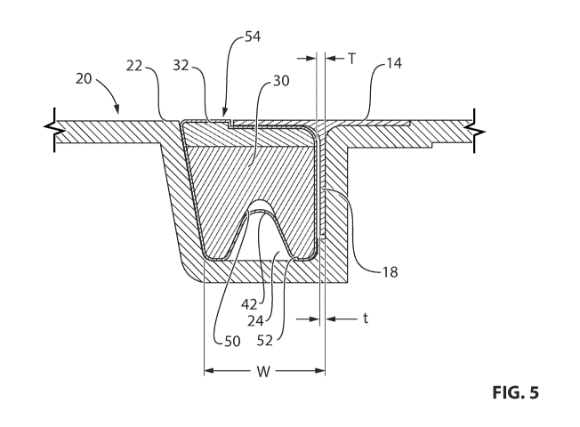
[0027] Fig. 5 is a schematic cross-sectional view of part of the assembly of
Fig. 3;
[0028] Fig. 6 is a schematic tridimensional view of a bagged insert used in
the
assembly of Fig. 3;
[0029] Fig. 7 is a schematic tridimensional view of a section of the assembly
of Fig. 3;
and
[0030] Fig. 8 is a schematic tridimensional exploded view of the section of
assembly
of Fig. 7.
DETAILED DESCRIPTION
[0031] Referring to the drawings and more particularly to Fig. 1, an aircraft
is shown
at 1, and is generally described to illustrate some components for reference
purposes
in the present disclosure. The aircraft 1 has a fuselage 2 having a fore end
at which a
cockpit is located, and an aft end supporting a tail assembly, with the cabin
generally
CA 03001279 2018-04-06
WO 2017/068497
PCT/1B2016/056257
located between the cockpit and the tail assembly. The tail assembly comprises
a
vertical stabilizer 3 with a rudder, and horizontal stabilizers 4 with
elevators. The tail
assembly has a fuselage-mounted tail, but other configurations may also be
used for
the aircraft 1, such as cruciform, T-tail, etc. Wings 5 project laterally from
the fuselage.
The aircraft 1 has engines 6 supported by the wings 5, although the engines 6
could
also be mounted to the fuselage 2. The aircraft 1 is shown as a jet-engine
aircraft, but
may also be a propeller aircraft.
[0032] Referring to Fig. 2, a composite part 10 according to a particular
embodiment
is shown. The composite part 10 is a panel including a skin 12 and a stiffener
or
stringer 14 extending from an inner surface 12i of the skin 12. The stringer
14 shown
has a T-shaped cross-section, with a base or flange 16 extending in contact
with the
inner surface 12i of the skin 12, and a leg or web 18 extending transversely
(e.g.
perpendicularly) from the base 16, for example along a central axis of the
base 16.
The stringer 14 is an elongated element extending longitudinally (i.e. along a
direction
perpendicular to the plane of the Figure).
[0033] Although the stringer 14 is shown as having a T-shaped cross-section,
it is
understood that the stringer 14 may alternately have any other appropriate
cross-sectional shape, including, but not limited to, a C-shaped cross-
section, an
L-shaped cross-section and an l-shaped cross-section.
[0034] In a particular embodiment and as can be more clearly seen in Fig. 3,
the skin
12 is curved. In another embodiment, the skin 12 is flat. The composite panel
10 may
define a section of the fuselage 2, part of an internal bulkhead, part of the
wing 5, or
any other appropriate structural element of the aircraft 1. Although a single
stringer 14
is shown in Figs. 2-3, it is understood that the composite panel 10 may and
typically
does include a plurality of stringers 14 spaced apart from one another, for
example as
shown in Fig. 4. As shown, the skin 12 may extend
circumferentially/transversely
beyond the stringer(s) 14. In a particular embodiment, each stringer 14
extends
longitudinally along only part of a corresponding dimension of the skin 12,
i.e. the skin
12 extends in the longitudinal direction beyond the stringer 14. In another
embodiment, the stringer 14 extends longitudinally along the entire
corresponding
dimension of the skin 12.
6
CA 03001279 2018-04-06
WO 2017/068497
PCT/1B2016/056257
[0035] The stringer 14 and skin 12 are formed with composite material, at
least one of
which being uncured with a stabilized geometry, i.e. having a matrix with a
reduced
viscosity without having been heated to the temperature point where
polymerization
typically starts (e.g., pre-preg); the stringer 14 or the skin 12 may be cured
prior to
assembly, such that curing of the uncured element assembled to the cured
element
provides fora co-bonding of the stringer 14 and skin 12. In the particular
embodiment
described herein, the skin 12 and stringer(s) 14 are both uncured with a
stabilized
geometry when assembled together, such as to be co-cured.
[0036] Although the method is described herein with specific reference to a
stringer
and skin assembly, it is understood that a similar method can be applied to
any
assembly of skin and stiffener(s), including, but not limited to, any
stiffened vehicle
structure (e.g. train roof) made of composite material.
[0037] Referring to Figs. 3-5, a method and assembly for manufacturing the
composite part 10 according to particular embodiment is shown. A mold 20 is
provided with a main mold surface 22 defining the inner mold line, in which is
defined
an elongated compaction cavity 24 for each stringer 14. As can be seen in Fig.
3,
each compaction cavity 24 is bordered by two elongated opposed side surfaces
26,
26' extending from the main mold surface 22, and interconnected by an
elongated
bottom surface 28. One of the side surfaces 26 defines a mold surface for the
stringer
14 which is a continuation of the inner mold line of the composite part, as
will be
detailed further below. The main mold surface 22 has a shape corresponding to
the
desired shape of the skin 12; in the particular embodiment shown, the skin 12
is
curved, and the main mold surface 22 is correspondingly convex (male tool).
[0038] Each compaction cavity 24 receives an elongated bagged insert 30
therein.
The bagged insert 30 is sized such that its top surface 32 forms a
continuation of the
main mold surface 22 (see Fig. 5), and such as to define an elongated space 34
(see
Fig. 3) between the side surface 36 of the bagged insert 30 and the adjacent
stringer
mold surface 26 of the compaction cavity 24.
[0039] Each stringer 14 is formed before being assembled with the skin 12. For
example, in the embodiment shown where the stringer 14 is T-shaped, the
stringer 14
may be formed by separately forming two L-shaped stringers and then assembling
them in a mirror position using an appropriate jig to form the T-shaped cross-
section.
7
CA 03001279 2018-04-06
WO 2017/068497
PCT/1B2016/056257
[0040] In a particular embodiment, each stringer 14 is assembled from plies of
pre-preg (pre-impregnated) composite material including fibers bonded by a
matrix
material having a stabilized geometry to facilitate handling, such that the
matrix
material becomes solid yet remains flexible and tacky.
[0041] In a particular embodiment, the matrix material is a B-stage resin or a
suitable
thermoplastic material; any appropriate type of thermoset or thermoplastic
matrix
material may be used, including but not limited to epoxy resin, bismaleimide
resin
(BMI), phenolic resin, polyvinyl ester resin, polyether ether ketone (PEEK),
polyphenylene sulphide (PPS), nylon, and poly ethylene (PE). Suitable fiber
materials
include, but not limited to, carbon fibers, glass fibers, and para-aramid
(Kev!are)
fibers, and the fibers may be provided in any appropriate form including, but
not
limited, bi-directional fibers such as woven fabric and non-crimp fabric
(NCF), and
unidirectional fibers. The stringer(s) 14 may alternately be formed using any
other
adequate method, including but not limited to vacuum assisted resin infusion
in
conjunction with a dry preform.
[0042] Each stringer 14 is uncured and in a shape-retaining condition, such
that it
may be transported (optionally with the help of an appropriate support) to be
added to
the assembly. In a particular embodiment, each stringer 14 is made of a
plurality of
layers of pre-preg material and is compacted by vacuum debulk between
placement
of the layers (intermediate ply debulk), at room temperature or under
temperature
slightly higher than room temperature to ease the forming of multiple pre-preg
layers
from flat to a particular shape (e.g. L or C).
[0043] Referring back to Figs. 3-5, each compaction cavity 24 receives a
stringer 14
therein, supported by the bagged insert 30 already in the compaction cavity
24. The
base 16 of the stringer 14 is received over the top surface 32 of the bagged
insert 30
and/or over the main mold surface 22; in the embodiment shown, since the
stringer 14
is T-shaped, the base 16 of the stringer 14 has one side 16a received over the
top
surface 32 of the bagged insert 30 and one side 16b received over the main
mold
surface 22 (see Fig. 3). As can be best seen in Figs. 3 and 5, the part of the
stringer 14
extending from the skin 12, i.e. the leg 18, is snuggly received in the
elongated space
34 defined between the side surface 36 of the bagged insert 30 and the
adjacent
stringer mold surface 26 of the compaction cavity 24. Referring to Fig. 5, the
8
CA 03001279 2018-04-06
WO 2017/068497
PCT/1B2016/056257
transverse dimension T of the elongated space 34 is selected based on the
thickness
t of the leg 18 received therein, such as to be large enough to allow
insertion of the
stringer leg 18 between the bagged insert 30 and the stringer mold surface 26,
but
small enough for the bagged insert 30 to retain the leg 18 in contact with the
stringer
mold surface 26. The surface finish of the stringer 14 differs between the
side in
contact with the mold surfaces 22,26 and the side that touches the surface of
the
bagged insert 30; accordingly, in a particular embodiment, the side of the
stringer 14
in contact with the bagged insert 30 is selected based on a desired surface
finish
configuration for the stringer 14.
[0044] Referring to Fig. 6, the bagged insert 30 includes an insert 40
received in a
tubular bag 42. The tubular bag 42 is made of any appropriate type of bagging
material used for compaction and cure of composite materials, and has at least
one
open end. The insert 40 includes two cooperating elongated portions: the top
portion
44 defines the top surface 32 of the insert and part of its side surfaces, and
the bottom
portion 46 defines the bottom surface of the insert and the remaining part of
its side
surfaces. In the embodiment shown, the top surface 32 supports one side 16a of
the
stringer base 16, and accordingly, the top portion 44 of the insert 40 is
tailored to the
geometry of the stringer 14 being supported; the top surface 32 is shaped to
correspond to the desired shape of the side 16a of the stringer base 16
received
thereon. In a particular embodiment, stringers 14 having different shapes may
be
supported by inserts 40 having a same bottom portion 46 but different top
portions 44
tailored to the particular shape of the respective stringer 14.
[0045] In the particular embodiment shown, the top surface 32 defined by the
top
portion 44 is designed to conform to a "grow-out" of the side 16a of the
stringer base
16 received thereon, i.e. a portion of the base 16 having an increased width.
The top
surface 32 of the top portion 44 thus defines an indent 48 having a contour
corresponding to that of the side 16a of the stringer base 16 received
thereon. The
mold surface 22 may also be similarly configured (see Fig. 8).
[0046] In a particular embodiment, the bottom portion 46 of the insert 40 has
an
elongated recess 50 defined along its length in one of its surfaces not
contacting the
stringer 14. In the embodiment shown, the recess 50 is defined in the bottom
surface
52. The tubular bag 42 is sized to surround a cross-sectional area greater
than the
9
CA 03001279 2018-04-06
WO 2017/068497
PCT/1B2016/056257
area of a cross-section of the insert 40; in other words, the insert 40 is
loosely
received within the bag 42, such that extra bag material is provided around
the insert
40. The recess 50 defined in the bottom portion 46 however defines an
increased
perimeter (as compared with a similarly sized insert without the recess), and
the
recess 50 defines a space for receiving excess material from the tubular bag
42 when
the tubular bag 42 is extended smoothly in contact with the surfaces of the
insert 40.
The recess 50 thus allows for reducing the risk of wrinkles in the tubular bag
42 over
the surfaces of the insert 40, thus reducing the risk of causing surface
defects in the
stringer 14 and skin 12 with the tubular bag 42.
[0047] In a particular embodiment, in a plane perpendicular to a longitudinal
axis of
the insert (i.e., plane of Fig. 5), the perimeter of the cross-section of the
insert 40 is at
least equal to, and preferably greater than, the maximum perimeter defined by
the
wall of the tubular bag 42. Accordingly, pushing the excess bag material at
its
maximal depth within the recess 50 extends the remainder of the bag material
over
the surfaces of the insert 40 such that it extends smoothly thereover.
[0048] In a particular embodiment, the interior cavity of the tubular bag 42
is
maintained at reduced pressure (e.g. vacuum) to ensure that the walls of the
bag 42
conform to the surfaces of the stringer 14 to avoid the formation of wrinkles;
the
reduced pressure within the tubular bag 42 is maintained at least until the
stringer 14
is placed over the bagged insert 30.
[0049] Once each stringer 14 is in position, the skin 12 is laid up over and
in contact
with the main mold surface 22, and over and in contact with the base 16 of
each
stringer 14, for example by hand, using automated fiber placement (AFP) , or
using
automated tape laying (ATL). In a particular embodiment, the skin 12 is made
of a
plurality of superposed pre-preg layers; suitable materials include, for
example, the
materials listed above for the stringer(s) 14. In another embodiment, the skin
12 can
be laid up using dry fabric. In the embodiment shown, the base 16 of the
stringer 14
does not completely cover the top surface 32 of the bagged insert 30; the top
surface
32 of the bagged insert 30 thus defines a step and an elevated portion 54 (see
Fig. 5)
aligned with the adjacent main mold surface 22, and also in contact with the
skin 12.
During the layup, each bagged insert 30 is thus acting as a hard tool by
supporting the
CA 03001279 2018-04-06
WO 2017/068497
PCT/1B2016/056257
pre-preg layers of the stringer 14 and skin 12, preventing the layers of pre-
preg from
falling into the compaction cavity 24.
[0050] Referring to Figs. 3-4, a mold element is placed over the skin 12 to
control the
outer surface 120 of the skin 12. It is understood that in the present
specification the
term "mold element" is intended to encompass any tool having a shape-defining
surface configured to control a surface of the part during curing, having any
appropriate thickness, including, but not limited to, pressure pads typically
referred to
as caul plates. In the embodiment shown, a caul plate 56 is placed over the
skin 12.
[0051] Additional elements may be added to the assembly as required, for
example
structural reinforcements in the form of radius fillers 70 ("noodles") of
uncured
material (see Fig. 3). In a particular embodiment, a radius filler 70 is
provided on the
base 16 of the stringer 14 at the junction between the two L-shaped parts
forming the
stringer, between the base 16 and the skin 12, and accordingly is positioned
before
the skin 12 is laid on the assembly. The radius filler 70 may deform during
compaction and/or during cure to conform to the profile of the junction
between the
two L-shaped parts of the base 16 and the skin 12. Suitable materials for such
radius
fillers 70 include, but are not limited to, any material compatible with the
resin used for
the skin 12 and stringer 14, which may include short fibers, surfacing film,
adhesive
film, foam adhesive, unidirectional or weaved carbon, glass or para-aramid
synthetic
(Kevla a) fibers.
[0052] In a particular embodiment and as can be seen in Figs. 7-8, the
compaction
cavity 24 has a length greater than that of the stringer 14, and a respective
end cap 78
is inserted into the compaction cavity 24 adjacent each end of the stringer
14. The end
caps 78 have a top surface aligned with the main mold surface 22, and provide
support for the portion of the skin 12 extending beyond the length of the
stringer 14, to
prevent the skin 12 from sagging into the compaction cavity 24. The end caps
78 may
also reduce resin bleeding through the ends of the stringer 14.
[0053] Once the elements of the assembly are in place, a sealed enclosure is
formed,
containing the caul plate 56, the skin 12, the stringer(s) 14 and the main
mold surface
22. The sealed enclosure is defined in part by each tubular bag 42, by sealing
engagement of its outer surface with the mold 20 and/or additional bagging
material;
each insert 40 is located outside of this sealed enclosure.
CA 03001279 2018-04-06
WO 2017/068497
PCT/1B2016/056257
[0054] In a particular embodiment and referring to Fig. 4, a top bagging
material 58 is
added over the caul plate 56. Breather material and release film (not shown)
are
installed as required; for example, in a particular embodiment, breather
material is
provided where the caul plate 56 would otherwise be in direct contact with the
main
mold surface 22, over the vacuum ports, etc., and a release film and breather
material
are installed over the caul plate 56 to prevent direct contact thereof with
the bagging
material 58. The top bagging material 58 encloses the caul plate 56, the
stringer(s) 14
and the skin 12 and is in sealing engagement with the main mold surface 22
around
the caul plate 56. For example, the sealing engagement may be provided by
engaging
the top bagging material 58 with a sealing material 60 (e.g. tacky compound,
double
faced tape) applied on the main mold surface 22 and disposed to form a closed
perimeter around the caul plate 56.
[0055] As can be seen more clearly in Figs. 7-8, in a particular embodiment,
the mold
20 includes an elevated or ramp surface 80 at each end (only one of which is
shown)
of the compaction cavity 24, which extends from the mold surface 22 and is
angled
such as to form a bridge extending over each compaction cavity 24, defining a
continuous surface of the mold 20 extending over the ends of the compaction
cavities
24; the sealing material 60 is received on the continuous surface of this
bridge. This
allows the top bagging material 58 (see Fig. 4) to be sealed to the mold 20
around its
entire perimeter without requiring a direct sealing engagement between the top
bagging material 58 and the tubular bags 40. Accordingly, if the top bagging
material
58 or one of the tubular bags 40 develops a leak, it can be replaced
independently
from the other. It is understood that the configuration of the elevated
surface 80 (e.g.
angle, profile) may vary from that shown.
[0056] If the ramp surface 80 is omitted, the compaction cavities 24 can have
an open
top along their entire length, and the top bagging material 58 can be
sealingly
engaged to the surface of the tubular bags 40 over the compaction cavities 24
and
with the mold 20 in between the compaction cavities 24.
[0057] At some time after positioning each stringer 14 on the respective
bagged
insert 30 and before forming the sealed enclosure, the interior of each
tubular bag 42
is returned to atmospheric pressure if a reduced pressure was applied within
the
interior of the bags. As can be seen in Figs. 4,7 and 8, the outer surface of
the open
12
CA 03001279 2018-04-06
WO 2017/068497
PCT/1B2016/056257
ends of each tubular bag 42 is sealingly engaged to the corresponding mold
ends
around the respective opening 62 defined by the open end of the compaction
cavity
24. For example the sealing engagement may be provided by engaging the outer
surface of the end of the tubular bag 42 with a sealing material 60' as
described above
disposed to form a closed perimeter around the opening 62 at the end of the
respective compaction cavity 24. The tubular bag(s) 42 and the top bagging
material
58 thus cooperate to define the sealed enclosure.
[0058] Once the sealed enclosure is formed, the pressure is reduced within the
sealed enclosure, for example by engaging a vacuum system 64 with one or more
vacuum ports 66 cooperating with the enclosure. The top bagging material 58
and
tubular bag(s) 42 defining the enclosure press the skin 12 and the stringer(s)
14
against the mold surfaces 22, 26 to provide for compaction of the assembly.
Each
tubular bag 42 thus applies uniform pressure on the corners, thickness
variations,
radius, joggles, grow-outs, etc. of the respective stringer 14, such as to
allow a
uniform compaction of the assembly. Once the assembly is compacted, each
insert
40 is removed from the respective tubular bag 42, and the assembly is cured
(e.g.
co-curing of the stringer(s) 14 and skin 12) while maintaining a reduced
pressure in
the sealed enclosure; the reduced pressure during cure may be the same as
during
compaction (prior to removal of each insert 40) or may be different, for
example lower.
The assembly can be cured in an oven, or under pressure in an autoclave. The
reduced pressure within the sealed enclosure ensures that the top bagging
material
58 and tubular bag(s) 42 provide the necessary compaction force against the
mold
surfaces 22,26 and caul plate 56 to compact the stringer(s) 14 and skin 12
during the
cure. Accordingly, the insert 40 provides support only prior to curing; when
the final
surface of the stringer 14 and skin 12 is formed under heat and pressure
during cure,
the tubular bag 42 alone compacts the stringer surface under vacuum.
[0059] In the embodiment shown and as can be seen in Fig. 4, each insert 40
extends
longitudinally beyond the mold 20 and out of the end of the respective
compaction
cavity 24, such as to facilitate removal of the insert 40 from the compaction
cavity 24
and tubular bag 42. In a particular embodiment, the insert 40 is removed from
the
tubular bag by first removing the bottom portion 46, thus allowing the top
portion 44 to
come down in the compaction cavity 24 and disengage from the base 16 of the
stringer 14; the top portion 44 is then removed. In the embodiment shown and
as can
13
CA 03001279 2018-04-06
WO 2017/068497
PCT/1B2016/056257
be seen in Fig. 6, the bottom portion 46 extends longitudinally beyond the top
portion
44 to facilitate grabbing of the bottom portion 46 independently of the top
portion 44
for removal. The contacting surfaces between the two insert portions 44, 46
may be
provided with a coating or a layer facilitating relative sliding movement
therebetween,
to facilitate independent removal of the insert portions 44, 46 from the
tubular bag 42;
for example, a Teflon tape may be provided on the contacting surfaces between
the
two insert portions 44, 46.
[0060] Since the inserts 40 are removed from the assembly before cure, they do
not
need to be made of a material able to resist the curing temperatures;
accordingly, less
expensive materials can be used. In a particular embodiment, the two insert
portions
44, 46 are made of a same material. In a particular embodiment, the two insert
portions 44,46 are made of polyurethane having a hardness of 70 Shore A or
more. In
another embodiment, any semi-rigid material having a sufficient strength to
support
the stringer 14 during layup can be used, including, but not limited to, any
appropriate
type of elastomeric material. In a particular embodiment, the use of semi-
rigid material
for the insert 40 allows the insert 40 to be more easily pulled out from a
curved
elongated compaction cavity 24, and to be pulled out from a compaction cavity
24
having more complex shape, for example a double curvature.
[0061] Although the present method has been described with respect to an inner
mold line molding process, it is understood that the insert or other elements
of the
method can alternately be used with an outer mold line (e.g. concave or
female)
molding process , particularly where elements extend from an outer surface of
the
skin and need to be accommodated in a cavity of the mold.
[0062] In a particular embodiment, the bagged insert 30 allows the use of an
inner
mold surface (e.g. convex or male) with an inner stiffener reinforced
structure, and
accordingly provides an opportunity for improved faying surface quality, thus
reducing
recurring cost by reducing shimming and assembly time; reduced shimming may
also
allow for weight savings.
[0063] In a particular embodiment, the removable insert 40 allows for the
elongated
compaction cavity 24 to have a width W (see Fig. 5) that is greater than the
thickness
t of the leg 18 of the stringer 14, which helps to prevent the cured stringers
14 from
getting stuck or "locked" in the elongated compaction cavity 24 when it is
time to
14
CA 03001279 2018-04-06
WO 2017/068497
PCT/1B2016/056257
remove the cured assembly from the mold. The free space in the compaction
cavity
24 left by the removal of the insert 40 allows movement of the cured stringer
14 along
the direction of the thickness t upon removal of the assembly from the mold,
which
may facilitate disengaging the cured assembly from the mold.
[0064] In a particular embodiment, the insert 40 with the recess 50 to
accommodate
excess bag material allows the use of standard tubular bags resistant to the
curing
temperature with a variety of insert shapes and sizes, while accommodating the
excess bag material in the recess to provide for wrinkle-free surfaces to
contact with
the stiffener 14 and skin 12. Use of standard tubular bags, as well as inserts
made of
a material not required to resist the temperatures of cure, may allow to
reduce the
costs of manufacturing the composite part.
[0065] In a particular embodiment, the two part insert 40 may allow for easy
customization of the insert shape to conform to particular shapes of the
stiffeners
being supported (e.g. double curvature, integrated design features for weight
and/or
cost optimization such as variable thickness, joggles, grow-outs), which may
facilitate
conformity with particular quality requirements.
[0066] In a particular embodiment, the use of a removable insert 40 avoids
problems
due to thermal expansion differentials which may occur with supports used
during
cure.
[0067] It is understood that any combination or sub-combination of the
elements of
the different embodiments is within the scope of this disclosure. While the
methods
and systems described herein have been described and shown with reference to
particular steps performed in a particular order, it will be understood that
these steps
may be combined, sub-divided or reordered to form an equivalent method without
departing from the teachings of the present invention. Accordingly, the order
and
grouping of the steps is not a limitation of the present invention.
[0068] Modifications and improvements to the above-described embodiments of
the
present invention may become apparent to those skilled in the art. The
foregoing
description is intended to be exemplary rather than limiting. The scope of the
present
invention is therefore intended to be limited solely by the scope of the
appended
claims.