Note: Descriptions are shown in the official language in which they were submitted.
Atin'y Docket No. 9101.037PCT
LOW ELECTROMAGNETIC FIELD ELECTROSURGICAL CABLE
CROSS-REFERENCE TO RELATED APPLICATIONS
100011 None.
100021 None.
STATEMENT REGARDING FEDERALLY
SPONSORED RESEARCH OR DEVELOPMENT
0003j None.
BACKGROUND OF '111E INVENTION
Field of the Invention
1100041 The present invention relates to an electrosurgical cable which is not
producing
electromagnetic EM-field in its vicinity (zero-EM pollution) and reduces risk
of electric
shock for the human subjects involved in the electrosurgical procedure.
Background of the Related Art
[0005] Electrosurgical cables are used to connect an electrosurgical generator
to an
electrosurgical surgical hand piece and deliver high voltage and gas flow from
the generator
to the electrosurgical handpiece. Conventional electrosurgical cables utilized
in
electrosurgical systems consist of one high voltage electrode placed inside an
electrically
insulating flexible tube. The high voltage electrode inside the insulting tube
creates strong
electromagnetic (EM)
1
Date recue/Date received 2023-04-06
CA 03001388 2018-04-06
WO 2017/066745
PCT/US2016/057310
field around the cable. Frequencies of the electrosurgical generators are
below 1 MHz, which
is associated with wavelengths A.> 300 m. Therefore, a conventional one-
electrode
electrosurgical cable effectively is a short antenna with length L<<2.
Radiated EM power is
low since antenna in far from the resonance; however, values of the electric
field in the near-
zone of the antenna are high due to high voltages applied to the electrode.
Local electric fields
can be as high as E¨V/D-1000 V/cm, taking very realistic separation between
the
electrosurgical cable and patient D-1 cm, that can readily appear during the
electrosurgical
procedure when cable is constantly moving with respect to the patient.
SUMMARY OF THE INVENTION
[00061 The present invention relates to an electrosurgical cable that connects
between an
electrosurgical unit and a handpiece or housing that does not produce an EM-
field or only a
negligible EM-field in its vicinity. The cable can be used with any
electrosurgical generator.
The cable is intended to simultaneously deliver gas flow and high voltage
electrical energy
required for electrosurgical unit operation. Conventional electrosurgical
cables utilized in the
electrosurgical probes use only one conductor inside the insulating tube to
which high voltage
is applied. In contrast, present invention utilizes two conductors, namely an
inner high voltage
conductor and an outer conductor (connected to patient pad). The critical
feature of present
invention is that inner conductor electrical insulation that provides the
following critical
function. High voltage applied to the central electrode (Uo) is chosen above
the breakdown
threshold (UBD) in order to initiate discharge on the electrosurgical
handpiece (U0 > UBD).
However, inside the cable a significant fraction of the applied voltage drops
on the inner
insulator, so that remaining voltage applied to the gas gap (Uflos) is below
the breakdown
threshold: Ugas UBD. This allows prevention of breakdown and ignition of
plasma discharge
inside the cable.
2
Attn'y Docket No. 9101.037PCT
100071 The present invention has two important benefits in comparison with
conventional
electrosurgical cables. First, the present cable is completely shielded and
therefore it does
not produce EM-field around itself in contrast with conventional
electrosurgical probe
cables which produce EM-field as regular short dipole antenna. Second, the
present
electrosurgical cable significantly reduces risk of electric shock of human
subjects involved
in electrosurgical procedure. Indeed, conventional electrosurgical cables can
possess
significant risk of electrical shock in case outer insulation layer is
compromised. In contrast,
compromising any insulators in the case when present invention is used may
either cause
human contact with shielded electrode or create short-circuit of the
electrosurgical unit.
Both events are electrically safe for the involved human subjects.
100081 In a preferred embodiment the present invention is an electrosurgical
cable
having an elongated outer conductor, an outer insulator surrounding said outer
conductor, said outer conductor and said outer insulator foiming a tube, an
elongated
inner conductor inside said tube, and an inner insulator surrounding said
inner
conductor. There is a channel between and interior surface of said tube and
said inner
insulator. Further, sizes and materials of conductors and insulators are
chosen so a
voltage applied to the inner conductor is higher than the breakdown voltage
and a
voltage applied to gas flowing within said channel is below than the breakdown
voltage.
The electrosurgical cable may further have an electrical connector connected
to said
inner electrode for connecting said inner electrode to an electrosurgical
power supply,
an electrical connector connected to said out electrode for connecting said
outer
electrode to a ground, and a fluid connector connected to said tube for
connecting said
tube to a fluid source.
3
Date recue/Date received 2023-04-06
CA 03001388 2018-04-06
WO 2017/066745
PCT/US2016/057310
100091 In another preferred embodiment, the present invention is an
electrosurgical cable
having an elongated outer conductor having an outer radius c, an outer
insulator
surrounding said outer conductor and having inner radius d and an outer radius
e, said outer
conductor and said outer insulator forming a tube, an elongated inner
conductor inside said
tube, said inner electrode having a radius a, an inner insulator surrounding
said inner
conductor, said inner insulator having an outer radius b. There is a channel
between and
interior surface of said tube and said inner insulator and the radii a, b, c,
d, e are selected
so a<b<cd--- e. Further, the radii a, b, c, d and e are selected so a total
applied voltage
(U0) is distributed between the inner insulator (Uin) and gas gap between
inner and outer
insulators (Ugas), so that U0 = U U gas. Still further, a, b, c, d and e
may be selected so
that Utiv--tVgas. For example, the radii may be selected as follows: a=0.25
mm, b=2.5 mm,
c=d=4 mm and e=5 mm.
BRIEF DESCRIPTION OF THE FIGURES
(00101 For a more complete understanding of the present invention and the
advantages thereof,
reference is now made to the following description and the accompanying
drawings, in which:
[00111 FIG. 1 is a perspective view of an electrosurgical cable in accordance
with a preferred
embodiment of the present invention with connectors on one end of the cable
and an
electrosurgical handpiece on the other end of the cable.
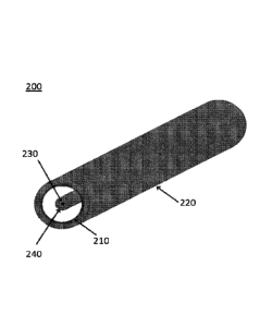
[00.112] FIG. 2 is a perspective view of a portion of a cable in accordance
with a preferred
embodiment of the present invention.
4
CA 03001388 2018-04-06
WO 2017/066745
PCT/US2016/057310
1.10131 FIG. 3 is a cross-section of a cable in accordance with a preferred
embodiment of the
present invention showing relationships of dimensions and voltage drops of
various component
parts of the cable.
DETAILED DESCRIPTION OF THE PREFERRED EMBODIMENT
[00.1.41 In describing a preferred embodiment of the invention illustrated in
the drawings
specific terminology will be resorted to for the sake of clarity. However, the
invention is not
intended to be limited to the specific terms so selected, and it is to be
understood that each
specific term includes all technical equivalents that operate in similar
manner to accomplish a
similar purpose. The preferred embodiment of the invention is described for
illustrative
purposes, it being understood that the invention may be embodied in other
forms not
specifically shown in the drawings.
1001.5 The present invention presents a novel concept of an electrosurgical
cable which
produces no EM-field or only negligible EM-field around itself (zero-EM
pollution) and offers
operation without risk of electric shock for human subjects involved in the
electrosurgical
procedure.
(0016) As shown in FIG. 1, a cable in accordance with the present invention
can be used in an
electrosurgical system, which, for example, may be a cold plasma
electrosurgical system, a
hybrid plasma electrosurgical system, or an argon coagulation electrosurgical
system. The
cable 200 of the present invention may have an electrical connector 400 and a
gas supply
connector 500 on one end and a handpice 300 on its other end. The electrical
connector will
have wiring 410 from the cable 200 and the gas connector will have a tube 510
from the cable
200. Various known connectors 400 and 500 may be used with the present
invention.
5
CA 03001388 2018-04-06
WO 2017/066745
PCT/US2016/057310
[00171 As shown in FIG. 2, the cable 200 has an inner electrode 230 to be
connected to an
electrosurgical generator, surrounded by insulation 240. When the cable is in
use, this inner
electrode 230 would be connected to a power supply through connector 400. In
the preferred
embodiment, the electrode 230 is made of cylindrical stainless steel wires of
0.25 mm radius
embedded in silicon rubber insulator with radius about 2.5 mm. Material and
diameter of the
wire is not limited to utilization of stainless steel and other electrically
conducting materials
can be used as well. Preferentially, diameter (a) of the wire 230 should be
chosen depending
on precise maximal current requirements of the specific electrosurgical
system. Radius (b) of
insulator 240 and its material can be varied in wide range as well. In the
preferred embodiment
silicon rubber was used as material for insulator 240 having relative
dielectric permittivity
3, however dielectrics with other values of E can be utilized as well.
Preferentially, flexible
electrically insulating material should be used to provide electrical
insulation along with good
flexibility of the electrosurgical cable as a whole.
[00181 The cable further has an outer electrode 210 to be connected to a
ground, surrounded
on its exterior by electrical insulator 220. As shown in FIGs. 2-3, the outer
conductor is
cylindrical and forms a tube within which the inner conductor and inner
insulation are placed
such that a fluid channel is formed between the outer conductor 210 and the
inner insulator
240. In the preferred embodiment, the outer electrode 210 is made of stainless
steel braided
sleeving embedded into outer insulating tube 220. Transparency of the braided
shield can be
varied depending on requirements of maximal cable weight. Lighter
electrosurgical cables can
be obtained by reducing diameter of the wire used in the braid and increasing
of its
transparency. Thin foil or other form of outer conductor can be used as well.
Minimal cross-
section of the outer conductor 210 should be limited by maximal electric
current values
required to be drawn through the particular electrosurgical cable. Inner
radius (c) of the outer
6
CA 03001388 2018-04-06
WO 2017/066745
PCT/US2016/057310
conductor 210 and outer radiuses (e) of insulator 220 and its material can be
varied.
Preferentially, flexible electrically insulating material should be used to
provide electrical
insulation along with good flexibility of the electrosurgical cable. The
braided shield can be
embedded inside the outer conductor and can have radius (d) in the range c =-
=cle. Note,
Figure 3 shows the case when inner diameter of the outer conductor 210 is
shown to be exactly
equal to diameter of outer conductor 220 (c=d) and inner electrode 230 and the
outer tube are
coaxial.
100191 In a preferred embodiment, the inner conductor and outer conductor are
cylindrical but
other shapes may be sued with the invention.
100201 In preferred embodiment Helium was used as working gas while other
gases such as
Argon can be used as well.
[0021] Relative sizes of the conductors 210, 230 and insulators 220, 240
should be chosen so
that a<b<cs".d: e. In preferred embodiment it was chosen a=0.25 mm, b=2.5 mm,
c=d=4 mm
and e=5 mm.
[0022] The total applied voltage (U0) is distributed between the inner
insulator (Ubi) and gas
gap between inner and outer insulators (Ugas), so that U0 = Uin + Ugas as
shown in Figure 2.
Ratio of voltages Uiii and Ugas, can be expressed as:
ln
U c gas Eln
10023] In preferred embodiment, the ratio uin _______________________________
¨1.1 meaning that Uin--=-,Ugas and thus using
Ugas
U0 = + Ugas one
can obtain the that Utiv-=-Vgas. In preferred embodiment, 4kV
was used and UBD was about 2.5 kV. Therefore,
kV and thus Ugas < UBD
7
Attn 'y Docket No. 9101.037PCT
providing that breakdown inside the electrosurgical cable prohibited. At the
same time,
U0 > UBD and thus the voltage is sufficient to produce breakdown at the
surgical handpiece.
Various combinations of radiuses and dielectric permittivity can be used,
however, it is
critical to choose theses parameters so that two conditions are simultaneously
satisfied:
1. U0 > UBD - voltage is sufficient to produce breakdown at the surgical
handpiece
2. Ugas < UBD - breakdown inside the electrosurgical cable is prohibited
1[00241 In the preferred embodiment, the inner electrode with insulator was
freely placed
inside the outer tube. However, relative location of the inner electrode with
insulator with
respect to the outer tube could be different such as coaxial or any other
relative positioning.
Also, inner insulator can be either permanently attached or not attached to
the inner wall of
the outer insulator.
[0025] The embodiment was chosen and described in order to explain the
principles of the
invention and its practical application to enable one skilled in the art to
utilize the invention
in various embodiments as are suited to the particular use contemplated. It is
intended that
the scope of the invention be defined by the claims appended hereto, and their
equivalents.
8
Date recue/Date received 2023-04-06