Note: Descriptions are shown in the official language in which they were submitted.
CA 03001446 2018-04-09
WO 2017/093358
PCT/EP2016/079344
1
NON-COMBUSTIBLE SMOKING DEVICE AND ELEMENTS THEREOF
The present invention relates generally to a non-combustible smoking device.
Electronic vaping devices are used to vaporize a pre-vapor formulation into a
vapor. These electronic vaping devices may be referred to as e-vaping devices.
E-
vaping devices include a heater, which vaporizes the pre-vapor formulation to
produce
the vapor. The e-vaping device may include several e-vaping elements including
a
power supply, a cartridge or e-vaping tank including the heater and a
reservoir capable
of holding the pre-vapor formulation.
At least one example embodiment of the present invention relates to a non-
combustible smoking device. The non-combustible smoking device may have at
least
one heater that heats a pre-vapor formulation and heats a tobacco element that
receives the vapor. More specifically, the non-combustible smoke device
according to
example embodiments exposes a vapor to a tobacco element, exposes a pre-vapor
formulation to a tobacco element, or both.
At least one example embodiment discloses a non-combustible smoking element
including a pre-vapor formulation reservoir element configured to contain a
pre-vapor
formulation material, a heating element coupled to the pre-vapor formulation
reservoir
element and configured to heat at least a portion of the pre-vapor formulation
material
into a vapor and provide the vapor to a first channel and a tobacco containing
element
defining at least a portion of the first channel, the tobacco containing
element
overlapping at least a portion of the heating element.
In an example embodiment, the tobacco containing element is an annular sleeve.
In an example embodiment, the tobacco containing element includes an inner
wall and an outer wall, the inner wall being permeable and the outer wall
being
impermeable.
In an example embodiment, the inner wall and the outer wall contain tobacco
plant material in any form.
In an example embodiment, the tobacco containing element is arranged such
that the vapor is delivered to the tobacco containing element upon an action
by an adult
vaper of the non-combustible smoking element.
In an example embodiment, the heating element is configured to be in thermal
communication with the tobacco containing element to heat at least a portion
of the
CA 03001446 2018-04-09
WO 2017/093358
PCT/EP2016/079344
2
tobacco containing element.
In an example embodiment, the heating element is configured to heat the
portion
of the tobacco containing element and produce an aroma from tobacco in the
tobacco
containing element.
In an example embodiment, the non-combustible smoking element further
includes a wick extending in a longitudinal direction from the pre-vapor
formulation
reservoir element.
In an example embodiment, the pre-vapor formulation reservoir element includes
an outer housing configured to contain the pre-vapor formulation material, an
inner tube
of the outer housing defining an air inlet, the wick in communication with the
pre-vapor
formulation reservoir element such that the wick is configured to draw the
portion of the
pre-vapor formulation material to be in thermal communication with the heating
element.
In an example embodiment, the heating element extends in the longitudinal
direction.
In an example embodiment, the tobacco containing element is adjacent a first
end of the outer housing.
In an example embodiment, the non-combustible smoking element further
includes an outer wall element on the tobacco containing element.
In an example embodiment, the outer wall element includes an outer wall part
and an inner wall part, the outer wall part and the tobacco containing element
defining
portions of a second air channel.
In an example embodiment, the outer wall element includes a cover at a first
end
of the inner wall part, the cover covering the first channel.
The above and other features and advantages of example embodiments will
become more apparent by describing in detail, example embodiments with
reference to
the attached drawings. The accompanying drawings are intended to depict
example
embodiments and should not be interpreted to limit the intended scope of the
claims.
The accompanying drawings are not to be considered as drawn to scale unless
explicitly noted.
FIG. 1 is a side view of a non-combustible smoking device according to an
example embodiment;
FIG. 2 is a cross-sectional view of the non-combustible smoking device of FIG.
1;
FIG. 3A illustrates an example embodiment of a non-combustible smoking device
CA 03001446 2018-04-09
WO 2017/093358
PCT/EP2016/079344
3
including a tobacco containing section having annular sleeves;
FIG. 3B illustrates an example embodiment of a non-combustible smoking device
including a tobacco containing section having annular sleeves
FIG. 30 illustrates an example embodiment of a non-combustible smoking device
including a tobacco containing section having annular sleeves;
FIG. 4 illustrates an air flow pattern of the non-combustible smoking device
shown in FIG. 3A;
FIG. 5 is an enlarged view of a heater of the non-combustible smoking device
of
FIG. 2;
FIG. 6 illustrates an example embodiment of an end of the tobacco containing
section of FIG. 2;
FIG. 7 illustrates an example embodiment of an end of the tobacco containing
section of FIG. 2; and
FIG. 8 illustrates an example embodiment of an end of the tobacco containing
section of FIG. 2.
Some detailed example embodiments are disclosed herein. However, specific
structural and functional details disclosed herein are merely representative
for purposes
of describing example embodiments. Example embodiments may, however, be
embodied in many alternate forms and should not be construed as limited to
only the
embodiments set forth herein.
Accordingly, while example embodiments are capable of various modifications
and alternative forms, embodiments thereof are shown by way of example in the
drawings and will herein be described in detail. It should be understood,
however, that
there is no intent to limit example embodiments to the particular forms
disclosed, but to
the contrary, example embodiments are to cover all modifications, equivalents,
and
alternatives falling within the scope of example embodiments. Like numbers
refer to like
elements throughout the description of the figures.
It should be understood that when an element or layer is referred to as being
"on," "connected to," "coupled to," or "covering" another element or layer, it
may be
directly on, connected to, coupled to, or covering the other element or layer
or
intervening elements or layers may be present. In contrast, when an element is
referred
to as being "directly on," "directly connected to," or "directly coupled to"
another element
CA 03001446 2018-04-09
WO 2017/093358
PCT/EP2016/079344
4
or layer, there are no intervening elements or layers present. Like numbers
refer to like
elements throughout the specification.
It should be understood that, although the terms first, second, third, and so
forth
may be used herein to describe various elements, regions, layers or sections,
these
elements, regions, layers, or sections should not be limited by these terms.
These
terms are only used to distinguish one element, region, layer, or section from
another
element, region, layer, or section. Therefore, a first element, region, layer,
or section
discussed below could be termed a second element, region, layer, or section
without
departing from the teachings of example embodiments.
Spatially relative terms (for example, "beneath," "below," "lower," "above,"
"upper," and the like) may be used herein for ease of description to describe
one
element or feature's relationship to one or more other elements or features as
illustrated
in the figures. It should be understood that the spatially relative terms are
intended to
encompass different orientations of the device in use or operation in addition
to the
orientation depicted in the figures. For example, if the device in the figures
is turned
over, elements described as "below" or "beneath" other elements or features
would then
be oriented "above" the other elements or features. Therefore, the term
"below" may
encompass both an orientation of above and below. The device may be otherwise
oriented (rotated 90 degrees or at other orientations) and the spatially
relative
descriptors used herein interpreted accordingly.
The terminology used herein is for the purpose of describing various
embodiments only and is not intended to be limiting of example embodiments. As
used
herein, the singular forms "a," "an," and "the" are intended to include the
plural forms as
well, unless the context clearly indicates otherwise. It will be further
understood that the
terms "includes," "including," "comprises," and "comprising," when used in
this
specification, specify the presence of stated features, integers, steps,
operations, or
elements, but do not preclude the presence or addition of one or more other
features,
integers, steps, operations, elements, or groups thereof.
Example embodiments are described herein with reference to cross-sectional
illustrations that are schematic illustrations of idealized embodiments (and
intermediate
structures) of example embodiments. As such, variations from the shapes of the
illustrations as a result, for example, of manufacturing techniques or
tolerances, are to
be expected. Therefore, example embodiments should not be construed as limited
to
CA 03001446 2018-04-09
WO 2017/093358
PCT/EP2016/079344
the shapes of regions illustrated herein but are to include deviations in
shapes that
result, for example, from manufacturing. Therefore, the regions illustrated in
the figures
are schematic in nature and their shapes are not intended to illustrate the
actual shape
of a region of a device and are not intended to limit the scope of example
embodiments.
5 Unless otherwise defined, all terms (including technical and scientific
terms) used
herein have the same meaning as commonly understood by one of ordinary skill
in the
art to which example embodiments belong. It will be further understood that
terms,
including those defined in commonly used dictionaries, should be interpreted
as having
a meaning that is consistent with their meaning in the context of the relevant
art and will
not be interpreted in an idealized or overly formal sense unless expressly so
defined
herein.
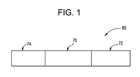
FIG. 1 illustrates a non-combustible smoking device 60 according to an example
embodiment. The non-combustible smoking device 60 includes a replaceable
cartridge
(or first section) 70, a reusable fixture (or second section) 72 and a tobacco
containing
section (or third section) 74.
FIG. 2 is a cross-sectional view of the non-combustible smoking device of FIG.
1.
As shown, the replaceable cartridge 70 and the reusable fixture 72 are coupled
together
at a connection 205a, 205b (for example, 205a is a male threaded connection on
cartridge 70, and 205b is a female threaded connection on reusable fixture 72)
or by
other convenience such as at least one of a snug-fit, detent, clamp, or clasp.
The first section 70 includes an outer tube 6 (or housing) extending in a
longitudinal direction and an inner tube 62 coaxially positioned within the
outer tube or
housing 6. The inner tube 62 defines a portion of an outer air passage (or
channel) 9.
A portion 75 of the tobacco containing section 74 fits within a circumference
defined by an inner portion of the outer tube 6 to create a frictional
connection between
the tobacco containing section 74 and the cartridge 70. Example embodiments
are not
limited to the frictional connection and other connections may be used.
Therefore, the
tobacco containing section 74 is a detachable insert.
The tobacco containing section 74 includes an inner tube 76 and an outer wall
78. The inner tube 76 of the tobacco containing section 74 defines another
portion of
the outer air passage 9. The outer wall 78 and the inner tube 76 define a
space
(annulus) therebetween.
CA 03001446 2018-04-09
WO 2017/093358
PCT/EP2016/079344
6
An end 201 of the tobacco containing section 74 may be a low efficiency
cellulose acetate filter, a hollow acetate tube, or a plastic or wood
mouthpiece. When
the end 201 is a plastic or wood mouthpiece, the end 201 is shaped such that a
portion
of the outer wall 78 fits within a circumference of the end 201. FIGS. 6-8
illustrate
example embodiments of the end 201.
Within the space between the outer wall 78 and the inner tube 76, the tobacco
containing section 74 includes a tobacco element 79. The term "tobacco
element" may
refer to any tobacco plant material including tobacco leaf, tobacco plug,
reconstituted
tobacco, compressed tobacco rod, shaped, or powder, for example.
In addition, the inner tube 76 and the outer wall 78 may contain tipping
paper, a
tobacco plant material in any form including rolled natural or reconstituted
tobacco leaf
or sheet or from an annular piece made of tobacco filler or extruded tobacco
in the
shape of a sleeve. The inner tube 76 and the outer wall 78 may be made of the
same
or different materials.
In an example embodiment, the tobacco containing section 74 may be a filtered
cigarette, a non-filtered cigarette, a cigarillo, a filter tipped cigar
filter, a tipped cigar, an
untipped cigar or an untipped cigarillo, for example. However, example
embodiments
are not limited thereto. If the tobacco containing section 74 is a shortened
cigarette, the
tobacco containing section 74 may include a filter at the end 201. In example
embodiments where the tobacco insert is an untipped cigar or an untipped
cigarillo, the
tobacco insert does not include a filter.
The filter may be a low efficiency cellulose acetate (CA) filter. CA filter
elements,
such as triacetin, can be eluted into vapor. Vapor phase nicotine and other
volatile
elements in vapor can be reduced by a presence of tobacco.
A heater 14 extends in a longitudinal direction from the inner tube 62 into
the
inner tube 76 in the outer air passage 9.
The second section 72 can also include the outer tube 6 extending in a
longitudinal direction. In an alternative embodiment, the outer tube 6 can be
a single
tube housing both the first section 70 and the second section 72 and the
entire non-
combustible smoking device 60 can be disposable.
The non-combustible smoking device 60 can also include a central air passage
20 defined in part by the inner tube 62 and an upstream seal 15. Moreover, the
non-
combustible smoking device 60 includes a pre-vapor formulation supply
reservoir 22.
CA 03001446 2018-04-09
WO 2017/093358
PCT/EP2016/079344
7
The pre-vapor formulation supply reservoir 22 comprises a pre-vapor
formulation
material and optionally a pre-vapor formulation storage medium 21 operable to
store the
pre-vapor formulation material therein.
In an embodiment, the pre-vapor formulation supply reservoir 22 is contained
in
an outer annulus between the outer tube 6 and the inner tube 62. The annulus
is sealed
at an upstream end by the seal 15. At a downstream end, the annulus is sealed
by a
gasket 62a. The gasket 62a may be a ring shaped gasket.
The gasket 62a is placed on the pre-vapor formulation supply reservoir 22 to
seal
the pre-vapor formulation in the pre-vapor formulation supply reservoir 22 and
prevent
the tobacco element 79 from mixing with the pre-vapor formulation.
In an embodiment, the heater 14 is also contained in the inner tube 62
downstream of and in spaced apart relation to the portion of central air
passage 20
defined by the seal 15. The heater 14 can be in the form of a wire coil, a
planar body, a
ceramic body, a single wire, a cage of resistive wire or any other suitable
form.
A wick 28 is in communication with the pre-vapor formulation material in the
pre-
vapor formulation supply reservoir 22 and in communication with the heater 14
such
that the wick 28 disposes pre-vapor formulation material in proximate relation
to the
heater 14. The wick 28 may be constructed of a fibrous and flexible material.
The wick
28 may include at least one filament having a capacity to draw a pre-vapor
formulation.
For example, the wick 28 may comprise a bundle of filaments which may include
glass
(or ceramic) filaments. In another embodiment, a bundle comprising a group of
windings of glass filaments, for example, three of such windings, all which
arrangements are capable of drawing pre-vapor formulation via capillary action
via
interstitial spacing between the filaments.
A power supply 1 in the second section 72 may be operably connected to the
heater 14 (as described below) to apply voltage across the heater 14. The non-
combustible smoking device 60 also includes at least one air inlet 44 operable
to deliver
air to the central air passage 20, other portions of the inner tube 62, or
both.
Moreover, the heater 14 extends in the longitudinal direction and heats the
pre-
vapor formulation material to a temperature sufficient to vaporize the pre-
vapor
formulation material and form a vapor when a negative pressure is applied to
the end
201. In other embodiments, the heater 14 may be arranged in another manner
such as
in a direction transverse to the longitudinal direction.
CA 03001446 2018-04-09
WO 2017/093358
PCT/EP2016/079344
8
The vapor then flows through the inner tube 76 and into the tobacco element 79
upon a negative pressure being applied at the end 201 of the tobacco
containing
section 74. The heater 14 may be a set distance from the tobacco element 79
such that
the heater 14 heats the tobacco element 79 when a negative pressure is
applied. For
example, the heater 14 may be about 10 millimeters or less from the inner tube
76.
The heater 14 may extend into the tobacco containing portion 74 between about
5 and about 20 millimeters. The heater 14 may be arranged to produce a
temperature
of about 50 degrees Celsius at the end 201. Moreover, the heater 14 may heat
the
tobacco element 79 to a temperature between about 50 and about 200 degrees
Celsius
and heat the pre-vapor formulation at between about 300 and about 350 degrees
Celsius.
The heater 14 warms the tobacco element 79, but does not burn the tobacco.
Therefore, the warming of the tobacco element 79 may be referred to as non-
combustible. Because the section 70 includes the heater 14 and the tobacco
containing
section 74 includes the tobacco element 79, the sections 70 and 74 may jointly
be
referred to as a non-combustible smoking element.
In one embodiment, the first section (the cartridge) 70 and the tobacco
containing
section 74 are disposable and the second section (the fixture) 72 is reusable.
The
sections 70, 72 can be attached by a threaded connection 205, as described
above,
whereby the downstream section 70 can be replaced when the pre-vapor
formulation
supply reservoir 22 is used up. Optionally, the first section 70 and the
second section 72
are arranged to releaseably lock together when engaged.
In an embodiment, the at least one air inlet 44 includes one or two air
inlets.
Alternatively, there may be three, four, five or more air inlets. If there is
more than one
air inlet 44, the air inlets 44 are located at different locations along the
non-combustible
smoking device 60. For example, as shown in FIG. 2, an air inlet 44a can be
positioned
at the upstream end of the non-combustible smoking device 60 adjacent a sensor
16
such that the sensor 16 supplies power to the heater 14 upon sensing a
negative
pressure. Air inlet 44a allows a negative pressure applied at the end 201 to
activate the
sensor 16. The air from the air inlet 44a can then flow along the power supply
1 and to
at least one of the central air passage 20 in the seal 15 and other portions
of at least
one of the inner tube 62 and the outer tube 6. At least one additional air
inlet 44 can be
located adjacent and upstream of the seal 15 or at any other desirable
location. Altering
CA 03001446 2018-04-09
WO 2017/093358
PCT/EP2016/079344
9
the size and number of air inlets 44 can also aid in establishing the
resistance to draw of
the non-combustible smoking device 60.
In an embodiment, the heater 14 is arranged to communicate with the wick 28
and to heat the pre-vapor formulation material contained in the wick 28 to a
temperature
sufficient to vaporize the pre-vapor formulation material and form a vapor.
The heater 14 may be a wire coil surrounding the wick 28. Examples of suitable
electrically resistive materials include titanium, zirconium, tantalum and
metals from the
platinum group. Examples of suitable metal alloys include stainless steel,
nickel-, cobalt-
, chromium-, aluminium- titanium- zirconium-, hafnium-, niobium-, molybdenum-,
tantalum-, tungsten-, tin-, gallium-, manganese- and iron-containing alloys,
and super-
alloys based on nickel, iron, cobalt, stainless steel. For example, the heater
may be
formed of nickel aluminides, a material with a layer of alumina on the
surface, iron
aluminides and other composite materials, the electrically resistive material
may
optionally be embedded in, encapsulated or coated with an insulating material
or vice-
versa, depending on the kinetics of energy transfer and the external
physicochemical
properties required. In one embodiment, the heater 14 comprises at least one
material
selected from the group consisting of stainless steel, copper, copper alloys,
nickel-
chromium alloys, superalloys and combinations thereof. In an embodiment, the
heater
14 is formed of nickel-chromium alloys or iron-chromium alloys. In one
embodiment, the
heater 14 can be a ceramic heater having an electrically resistive layer on an
outside
surface thereof.
In another embodiment, the heater 14 may be constructed of an iron-aluminide
(for example, FeAl or Fe3A1), such as those described in U.S. Pat. No.
5,595,706
to Sikka et al. filed Dec. 29, 1994, or nickel aluminides (for example,
Ni3A1). FeAl
exhibits a resistivity of approximately 180 micro-ohms, whereas stainless
steel exhibits
approximately 50 to 91 micro-ohms. The higher resistivity lowers current draw
or load
on the power supply (battery) 1.
In one embodiment, the heater 14 comprises a wire coil which at least
partially
surrounds the wick 28. In that embodiment, the wire may be at least one of a
metal wire
and the heater coil that extends partially along the length of the wick 28.
The heater coil
may extend fully or partially around the circumference of the wick 28. In
another
embodiment, the heater coil is not in contact with the wick 28.
CA 03001446 2018-04-09
WO 2017/093358
PCT/EP2016/079344
The heater 14 heats the pre-vapor formulation in the wick 28 by thermal
conduction. Alternatively, heat from the heater 14 may be conducted to the pre-
vapor
formulation by means of a heat conductive element or the heater 14 may
transfer heat
to the incoming ambient air that is drawn through the non-combustible smoking
device
5 60 during use, which in turn heats the pre-vapor formulation by
convection.
In one embodiment, the wick comprises a ceramic material or ceramic fibers. As
noted above, the wick 28 is at least partially surrounded by the heater 14.
Moreover, in
an embodiment, the wick 28 extends through opposed openings in the inner tube
62
such that end portions 29, 31 of the wick 28 are in contact with the pre-vapor
10 formulation supply reservoir 22.
The wick 28 may comprise a plurality or bundle of filaments. In one
embodiment,
the filaments may be generally aligned in a direction transverse to the
longitudinal
direction of the non-combustible smoking device 60, but the example
embodiments are
not limited to this orientation. In one embodiment, the structure of the wick
28 is formed
of ceramic filaments capable of drawing the pre-vapor formulation via
capillary action
via interstitial spacing between the filaments to the heater 14. The wick 28
can include
filaments having a cross-section which is generally cross-shaped, clover-
shaped, Y-
shaped or in any other suitable shape.
The wick 28 includes any suitable material or combination of materials.
Examples
of suitable materials are glass filaments, surface treated steel wires, and
ceramic or
graphite based materials. Moreover, the wick 28 may have any suitable
capillarity to
accommodate pre-vapor formulations having different physical properties such
as
density, viscosity, surface tension and vapor pressure. The capillary
properties of the
wick 28, combined with the properties of the pre-vapor formulation, ensure
that the wick
28 is always wet in the area of the heater 14 to avoid overheating of the
heater 14.
Instead of using a wick, the heater can be a porous material of sufficient
capillarity and which incorporates a resistance heater formed of a material
having a high
electrical resistance capable of generating heat quickly.
In one embodiment, the wick 28 and the pre-vapor formulation storage medium
21 of the pre-vapor formulation supply reservoir 22 are constructed from an
alumina
ceramic. In another embodiment, the wick 28 includes glass fibers and the pre-
vapor
formulation storage medium 21 includes a cellulosic material or polyethylene
terephthalate.
CA 03001446 2018-04-09
WO 2017/093358
PCT/EP2016/079344
11
In an embodiment, the power supply 1 may include a battery arranged in the non-
combustible smoking device 60 such that the anode is downstream of the
cathode. An
anode connector 4 contacts the downstream end of the battery. The heater 14 is
connected to the battery by two spaced apart electrical leads.
The connection between the uncoiled, end portions 27, 27' (see FIG. 5) of the
heater 14 and the electrical leads are highly conductive and temperature
resistant while
the heater 14 is highly resistive so that heat generation occurs primarily
along the
heater 14 and not at the contacts. The end portion 27 is connected to the
anode
connector 4 and the end portion 27' is connected to the cathode through the
outer tube
6.
The battery may be a Lithium-ion battery or one of its variants, for example a
Lithium-ion polymer battery. Alternatively, the battery may be a Nickel-metal
hydride
battery, a Nickel cadmium battery, a Lithium-manganese battery, a Lithium-
cobalt
battery or a fuel cell. In that case, the non-combustible smoking device 60 is
usable until
the energy in the power supply is depleted. Alternatively, the power supply 1
may be
rechargeable and include circuitry allowing the battery to be chargeable by an
external
charging device. In that case, the circuitry, when charged, provides power for
a desired
(or alternatively a pre-determined) number of applications of negative
pressure, after
which the circuitry must be re-connected to an external charging device.
The non-combustible smoking device 60 also includes control circuitry
including
the sensor 16. The sensor 16 is operable to sense an air pressure drop and
initiate
application of voltage from the power supply 1 to the heater 14.
The air inlet 44a is located adjacent the sensor 16, such that the sensor 16
senses air flow indicative of a negative pressure and activates the power
supply 1.
A control circuit is integrated with the sensor 16 and supplies power to the
heater
14 responsive to the sensor 16, for example, with a maximum, time-period
limiter.
Alternatively, the control circuitry may include a manually operable switch to
initiate an application of negative pressure. The time-period of the electric
current
supply to the heater may be pre-set depending on the amount of pre-vapor
formulation
desired to be vaporized. The control circuitry may be programmable for this
purpose.
Alternatively, the circuitry may supply power to the heater as long as the
sensor 16
detects a pressure drop.
CA 03001446 2018-04-09
WO 2017/093358
PCT/EP2016/079344
12
When activated, the heater 14 heats a portion of the wick 28 surrounded by the
heater for less than about 10 seconds, more preferably less than about 7
seconds.
Therefore, the power cycle can range in period from about 2 seconds to about
10
seconds (for example, about 3 seconds to about 9 seconds, about 4 seconds to
about 8
seconds or about 5 seconds to about 7 seconds).
In an embodiment, the pre-vapor formulation supply reservoir 22 includes the
pre-vapor formulation storage medium 21 containing pre-vapor formulation
material. In
FIG. 2, the pre-vapor formulation supply reservoir 22 is contained in an outer
annulus
between inner tube 62 and outer tube 6 and between gasket 10 and the seal 15.
Therefore, the pre-vapor formulation supply reservoir 22 at least partially
surrounds the
central air passage 20 and the heater 14 and the wick 28 extend between
portions of
the pre-vapor formulation supply reservoir 22.
The pre-vapor formulation storage medium 21 may be a fibrous material
comprising cotton, polyethylene, polyester, rayon and combinations thereof.
The fibers
may have a diameter ranging in size from about 6 microns to about 15 microns
(for
example, about 8 microns to about 12 microns or about 9 microns to about 11
microns).
The pre-vapor formulation storage medium 21 may be a sintered, porous or
foamed
material. Also, the fibers may be sized to be irrespirable and can have a
cross-section
which has a y shape, cross shape, clover shape or any other suitable shape.
In another example embodiment, the pre-vapor formulation storage medium 21
may be a tobacco filler or tobacco slurry.
Also, the pre-vapor formulation material has a boiling point suitable for use
in the
non-combustible smoking device 60. If the boiling point is too high, the
heater 14 will not
be able to vaporize the pre-vapor formulation in the wick 28. However, if the
boiling
point is too low, the pre-vapor formulation may vaporize without the heater 14
being
activated.
A pre-vapor formulation is a material or combination of materials that may be
transformed into a vapor. For example, the pre-vapor formulation may be at
least one
of a liquid, solid, and gel formulation including, but not limited to, water,
beads, solvents,
active ingredients, ethanol, plant extracts, natural or artificial flavors,
vapor formers such
as glycerine and propylene glycol, and combinations thereof.
The pre-vapor formulation may include a tobacco element including volatile
tobacco flavor compounds which are released upon heating. When the tobacco
CA 03001446 2018-04-09
WO 2017/093358
PCT/EP2016/079344
13
element is in the pre-vapor formulation the physical integrity of the tobacco
element is
preserved. For example, the tobacco element may be between about 2% and about
30% by weight in the pre-vapor formulation.
For example, the tobacco element may be in the form of a sheet or shreds and
is
added after the pre-vapor formulation is added to the pre-vapor formulation
storage
medium 21.
In operation, with non-combustible smoking device 60 in an assembled
configuration, a negative pressure may be applied on the end 201. This may
cause an
internal pressure drop inside non-combustible smoking device 60 that may cause
an
inlet air flow to enter device 60 via air inlets 44, 44a. The internal
pressure drop may
also cause an internal pressure drop within section 72 as air is drawn through
air inlet
44a (via an air flow path traveling through section 72). The internal pressure
drop
formed in section 72 may be sensed by sensor 16. The sensor 16 may then
operate to
close an electrical circuit that includes the power supply 1. In turn,
electrical leads carry
an electrical current to heater 14 in order to energize the heater 14. The
energized
heater 14 in turn heats and vaporizes the pre-vapor formulation material that
is drawn
toward the heater 14 via the wick 28.
The pre-vapor formulation material is transferred from one or both of the pre-
vapor formulation supply reservoir 22 and the pre-vapor formulation storage
medium 21
in proximity of the heater 14 by capillary action in the wick 28. In one
embodiment, the
wick 28 has a first end portion 29 and a second opposite end portion 31. The
first end
portion 29 and the second end portion 31 extend into opposite sides of the pre-
vapor
formulation storage medium 21 for contact with pre-vapor formulation material
contained therein. The heater 14 at least partially surrounds a central
portion of the wick
28 such that when the heater 14 is activated, the pre-vapor formulation in the
central
portion of the wick 28 is vaporized by the heater 14 to vaporize the pre-vapor
formulation material and form vapor. Due to a negative pressure being applied,
the
vapor flows from the heater 14, through the tobacco element 79 and out of the
end 201.
The vapor may elute tobacco elements into the flow stream. Some thermal
reactions may also be present between the vapor and the tobacco element.
One advantage of an embodiment is that the pre-vapor formulation material in
the pre-vapor formulation supply reservoir 22 is protected from oxygen
(because
oxygen cannot generally enter the pre-vapor formulation storage portion via
the wick) so
CA 03001446 2018-04-09
WO 2017/093358
PCT/EP2016/079344
14
that the risk of degradation of the pre-vapor formulation material is
significantly reduced.
Moreover, in some embodiments in which the outer tube 6 is not clear, the pre-
vapor
formulation supply reservoir 22 is protected from light so that the risk of
degradation of
the pre-vapor formulation material is significantly reduced. Therefore, a high
level of
shelf-life and cleanliness can be maintained.
The arrangement of the section 70 is not limited to the embodiment shown in
FIG. 2 and may include other modifications such as those described in U.S.
Patent
Application. No. 14/572,360.
One or both of the outer tube 6 and the inner tube 62 may be formed of any
suitable material or combination of materials. Examples of suitable materials
include
metals, alloys, plastics or composite materials containing one or more of
those
materials, or thermoplastics that are suitable for food or pharmaceutical
applications, for
example polypropylene, polyetheretherketone (PEEK), ceramic, and polyethylene.
In
one embodiment, the material is light and non-brittle.
While FIG. 2 illustrates the tobacco containing section 74 having a singular
annular sleeve, example embodiments are not limited thereto.
FIG. 3A illustrates an example embodiment of a non-combustible smoking device
including a tobacco containing section 74' having annular sleeves 74a and 74b.
A non-
combustible smoking device 300 is similar to the non-combustible smoking
device 60.
Therefore, for the sake of brevity, only the differences will be described.
In FIG. 3A, a tobacco containing section 74' includes annular sleeves 74a and
74b.
The annular sleeve 74a includes an inner tube 76' and an outer wall 78'. The
inner tube 76' defines another portion of the outer air passage 9. The outer
wall 78' and
the inner tube 76' define a space (annulus) therebetween. The outer wall 78'
and the
inner tube 76' may be made of the same materials of the outer wall 78 and
inner tube
76, respectively.
Within the space between the outer wall 78' and the inner tube 76' is the
tobacco
element 79.
The annular sleeve 74b includes an inner tube 305 and an outer wall 310. As
shown in FIG. 3A, the annular sleeve 74b encompasses the annular sleeve 74a.
The
inner tube 305 is permeable and the outer wall 310 is impermeable. An end 315
of the
annular sleeve 74b is closed to air flow. The end 315 may be made of any
material that
CA 03001446 2018-04-09
WO 2017/093358
PCT/EP2016/079344
acts as a plug to block airflow such as a plastic (for example, polyethylene)
or a metal.
Therefore, air flows from the air passage 9, through the annular sleeve 74a
through the
inner tube 305 and into air channels 320, 325 upon applying a negative
pressure to the
tobacco containing section 74", as shown in FIG. 4.
5
The inner tube 305 is a permeable material such as a membrane, mesh,
perforated plastic or paper. The inner tube 305 is made of a material that
maintains the
structural integrity of the annular sleeve 74b. The outer wall 310 is an
impermeable
material such as a plastic.
FIG. 3B illustrates another example embodiment of a non-combustible smoking
10
device including a tobacco containing section 74" having annular sleeves 74a'
and 74b'.
The tobacco containing section 74" is similar to the tobacco containing
section
74'. Therefore, only the differences will be described.
In FIG. 3B, an annular sleeve 74b' does not include the inner tube 305.
Instead,
an outer wall 78" of the annular sleeve 74a' is also part of the annular
sleeve 74b'. With
15
an inner tube 76", the outer wall 78" and the inner tube 76" define a space
(annulus)
therebetween. Within the space between the outer wall 78" and the inner tube
76" is
the tobacco element 79.
As shown in FIG. 3B, the outer wall 78" and the inner tube 76" extend to the
end
315. The outer wall 78" and the inner tube 76" may be made of the same
materials as
the outer wall 78' and the inner tube 76", respectively.
FIG. 30 illustrates another example embodiment of a non-combustible smoking
device including a tobacco containing section 74¨.
The tobacco containing section 74¨ is similar to the tobacco containing
section
74". Therefore, only the differences will be described.
In FIG. 3B, an inner tube 76¨ of an annular sleeve 74a" is closed off before
the
end 315. A space is then defined between the end 315 and the inner tube 76¨.
Tobacco element 79 is also between the end 315 and the inner tube 76¨.
The non-combustible smoking devices according to example embodiments are
effective in heating the tobacco and distilling and eluting tobacco specific
flavors
because of their flow pattern and proximity of the tobacco element to the
heater 14
(vapor forming area). The perpendicular flow, shown in FIG. 4, of the vapor
from the
heater 14 to the tobacco element and the closeness of the tobacco to the
heater 14
CA 03001446 2018-04-09
WO 2017/093358
PCT/EP2016/079344
16
allow for effective heating of the tobacco and subsequent distillation and
elution of
volatile tobacco flavors.
While example embodiments illustrate that vapor can exit the non-combustible
smoking device in an annular fashion, it should be understood that the vapor
may exit in
a concentric fashion.
FIG. 6 illustrates an example embodiment of an end of the tobacco containing
section 74 being a plastic mouthpiece. As shown in FIG. 6, an end 201a has at
least
two off-axis, diverging outlets 24. The end 201a is in fluid communication
with the
central air passage 9, which extends through a gasket 10. The gasket 10 is at
a
downstream end of the tobacco containing section 74 so as to prevent leakage
of the
tobacco material into the end 201.
A portion of the outer wall 78a fits within a circumference of the end 201a.
Due to a negative pressure being applied to the tobacco containing section 74,
the vapor flows from the heater 14, through the tobacco containing section 74
and out of
the end 201a.
FIG. 7 illustrates an example embodiment of an end of the tobacco containing
section 74.
An end 201b fits over a portion of the outer wall 78b. A negative pressure may
be applied on the end 201b. Due to the negative pressure, the vapor flows from
the
heater 14, out of the tobacco containing section 74 through an air passage
700.
FIG. 8 illustrates an example embodiment of an end of the tobacco containing
section 74.
An end 201c includes a filter 800. In example embodiments where the tobacco
insert is an untipped cigar or an untipped cigarillo, the tobacco insert does
not include a
filter.
Tipping paper 805 may overlap the filter 800. Tipping paper may also be used
as
the wall 78. Therefore, the tipping paper 1255 provides stiffness to the
tobacco
containing section 74, permitting easier insertion to the cartridge 70. An
aluminum foil
may also be used to contain the tobacco element, with or without additional
tipping
paper.
In the example shown in FIG. 8, the filter 800 may be a cellulose acetate (CA)
filter. CA filter elements, such as triacetin, can be eluted into vapor. Vapor
phase
nicotine and other volatile elements in vapor can be reduced by a presence of
tobacco.
CA 03001446 2018-04-09
WO 2017/093358
PCT/EP2016/079344
17
When a negative pressure is applied to the tobacco containing section 74, the
vapor flows from the heater 14, through the tobacco containing section 74 and
out of the
filter 800.
Example embodiments provide a non-combustible smoking device having a
heater that heats a pre-vapor formulation and may provide heat to a tobacco
element.
More specifically, the non-combustible smoke device according to example
embodiments exposes a vapor to a tobacco element, exposes a pre-vapor
formulation
to a tobacco element, or both. When the tobacco element is in the pre-vapor
formulation the physical integrity of the tobacco element is preserved.
In other example embodiments, a non-combustible smoke device can be a pod
device or tank device that exposes a vapor to a tobacco element, exposes a pre-
vapor
formulation to a tobacco element, or both.
While a single heater is described with reference to FIGS. 1-8, example
embodiments may include a multiple heater non-combustible smoking device. A
first
heater may be the heater 14 to vaporize the pre-vapor formulation and a second
heater
may be used to heat the tobacco element. The second heater may penetrate the
tobacco element.
In other example embodiments, a non-combustible smoking device includes
more than two heaters.
Example embodiments having therefore been described, it will be obvious that
the same may be varied in many ways. Such variations are not to be regarded as
a
departure from the intended scope of example embodiments, and all such
modifications
as would be obvious to one skilled in the art are intended to be included
within the
scope of the following claims.