Note: Descriptions are shown in the official language in which they were submitted.
CA 03001809 2018-04-10
WO 2016/061164 PCT/US2015/055427
1
METHOD AND SYSTEM OF COMPRESSING
GAS WITH FLOW RESTRICTIONS
This is application claims the benefit of priority of U.S. patent application
serial
no: 14/880,378, filed October 12, 2015, and U.S. provisional patent
application serial
number 62/222,261, filed September 23, 2015 and U.S. provisional patent
application
serial number 62/063,463, filed October 14, 2014, both of which are currently
pending.
Technical Field
The present invention relates to gas compressors using a method of compressing
gas with centrifugal forces and using flow restriction technology.
BACKGROUND ART
Gas compressors are used for many items in the consumer market (to inflate
basketballs, toys and tires) and in the industrial market (to compress gas for
transport, for
powering pneumatic tools and for distributing natural gas from the well head
to the user).
The efficiency of prior art commercial gas compressors is poor primarily
because
practicalities require that the gas be compressed rapidly. Rapid compression
makes it
nearly impossible to dissipate the heat of compression during the compression
process.
This inherent heating during the compression process (herein "C-heat") demands
up to
100% More physical work from the prime mover than if the same process was done
with
complete and immediate "C-heat" removal. Typically the prime mover is an
internal
combustion engine or an electric motor. A rapid compression process with
little or no
C-heat removal is called an adiabatic compression. Most state of the art
compressors
operate with adiabatic or semi-:adiabatic compression cycles. The energy or
work lost due,
to C- beat increases as the final target pressure for the compressor
increases.
The work potential of the isothermally compressed gas is roughly equivalent to
the work required to compress the gas However, most compressed gas is stored
in an
uninsulated pressure vessel and the time between the compression of the. gas
and the use
of the gas makes retention of the heat in the gas impractical. Therefore, this
50-100%
additional work to overcome the C-heat While compressing the gas is lost or
wasted.
CA 03001809 2018-04-10
WO 2016/061164 PCT/US2015/055427
2
Compression performed while immediately removing all of the C-heat is called
isothermal compression. If isothermal compression can be achieved, the energy
required
to compress gas to a given pressure could theoretically be cut nearly in half
Stated
otherwise, twice the amount of compressed gas could be produced for the same
cost in
energy or dollars. Historically isothermal compression has been impractical or
impossible
to achieve because the C-heat removal from the compressed gas requires too
much time
and/or additional energy for practical use.
One prior art references discusses a compressor with rapid isothermal
compression. U.S, Patent No. 892,772 to Taylor, patented in 1908, discloses a
hydraulic
air compressor which utilizes a falling column of water infused with millions
of tiny
spherical bubbles. When the column of water falls from a particular height,
the bubbles
in the water are compressed. Taylor .. used a 70 foot differential head
pressure (about 21
meters) which creates roughly 30 PSI differential pressure to drive the
compression
process. Taylor used a 290 foot (about 88 meters) tall tail race to create and
maintain
approximately 128 psi (pounds per square inch) pressure to drive 5000-6000
horsepower
isothermal compressors.
U.S. Patent Serial No, 14/280,780, filed May 19. 2014, U.S, Patent Application
Publication No. 20150023807 (published January 22, 2015) to Cherry et al
discloses a
centrifugal compressor that compresses gas in capillaries leading to a
radially distant
annular container space. Centrifugal force acts on gas bubbles entrained
between liquid
slugs moving radially outward (distally) through the capillary compression
tubes which
may be radial, tangential or continuously curved. Compressed gas is collected
in an
annular pressurized gas separation and storage chamber, whereupon it is
harvested for
industrial use, At the input side, a gas-liquid emulsion is fed to the
capillary compression
tubes by an inboard emulsification device. The emulsification device may
include a
vortex generator, an ejector or a venturi injector, all feeding the gas-liquid
mixture into
the inboard ports of the capillaries, The capillaries are formed in a series
of discs,
coaxially stacked with outer disc ends open to the annular disc space.
CA 03001809 2018-04-10
WO 2016/061164
PCT/US2015/055427
3
PatentNo. 6,276,140 to Keller discloses a device to generate energy through
a turbine engine. The Keller device also uses falling water fed through a
funnel shaped
vertical tube or tunnel in order to compress air bubbles in the falling water.
The waterfall
drop in Keller was between 30-100 meters. Typical diameters at the top of the
Keller
funnel tube arc approximately 2-7 meters and, at the bottom, the funnel outlet
region is
typically 0.7-2.0 meters.
U.S. Patent No. 1,144,865 to Rees discloses a rotary pump, condenser and
compressor, l'he Rees '865 rotary pump compressor utilizes large cavities
havMg highly
curved shaped walls and the cavities are not radial with respect to the
rotating container.
U.S. Patent Application Publication No. 2011/0030359 to Fong generally
discusses a centrifugal separator. U.S, Patent Application Publication No.
2011/0115223
to Stahlkopf also discusses centrifugal separators. Neither long '359 or
Stahlkopf '223
discuss a centrifugal compressor which compresses bubbles in water or a liquid
in an
isothermal manner to extt'act the compressed air or gas.
U.S. Patent No. 1,769,260 to Hughes discloses a centrifugal pump and condenser
that uses capillary tubes to compress gas bubbles. However the manner in which
fIughes
creates a bubble train results in much longer and larger bubbles - with
correspondingly
greater bubble buoyancy - such that it is very difficult to force the bubbles
towards the
distal end of the compression tube. Hughes' shroud is a trough that collects
water as it
leaves the capillary chambers. `file trough fills with water trapped due to
centrifugal force
at a depth determined by the inward facing flanges. Water which passes over
these
flanges is drained to the inside wall of a stationary cylindrical casing. The
radially
outboard ends of the capillary chambers extend radially beyond the internal
diameter of
the inwardly facing flanges creating a gas seal.
Hughes' shroud design has no significant pressure differential. Although
Hughes'
shroud acts as a seal by throwing the gas-liquid mixture at the radially
remote inboard
walls, the shroud design does not act as a rectifying agent to force
unidirectional distal
flow of entrained bubbles. Hughes's shroud design also does not provide a
pressurized
CA 03001809 2018-04-10
WO 2016/061164
PCT/US2015/055427
4
gas storage housing and a gas/liquid separation chamber. Hughes also does not
disclose
a method of recovering the kinetic energy imparted to the water by the
impeller, therefore
the gains of isothermal compression would be wasted on the energy imparted to
the
water.
DISCLOSURE OF THE INVENTION
The present inventive method of compressing gas and the gas compressor (1)
creates and enforces distally unidirectional emulsion flow through the
capillary
compression tubes and (2) maintains in some embodiments, bubble-tube wall,
full
diameter contact throughout the critical section of the capillary tubes in a
centrifugal
1(1 bubble compressor.
The present method creates, enforces and enhances distally oriented
unidirectional emulsion flow in the capillary compression tubes through the
use of
mechanical checking of radially inboard flow, dynamic enforcement of distal
radially
outboard emulsion flow, checking bubble buoyancy towards the inboard or
proximal
ends of the tubes, countering emulsion exit velocity, and tapering the tube
diameters
longitudinally to match the rate of bubble diameter reduction during
compression.
Emulsion flow or gas bubble "slip" in the proximal direction (towards the axis
of rotation) represents work lost by the device.
Fully checked or rectified (nonreversible) emulsion flow through capillary
compression tubes in a generally radially outboard direction is unidirectional
by
definition. Its velocity may vary or even stop, but flow can only proceed in
one direction.
Tvlechanical checking mechanisms are one method class that can be added to the
capillary
compression tubes to create complete distally oriented unidirectional emulsion
flow.
Enforced distally oriented uni directional emulsion flow through capillary
compression tubes occurs when a method is employed which guards against
reverse flow.
Rotating dedicated ejector mechanisms and capillary compression tubes that
have a
tapered diameter are two method classes that can be added to the capillary
compression
tubes in this device to enforce complete distally oriented unidirectional
emulsion flow.
CA 03001809 2018-04-10
WO 2016/061164
PCT/US2015/055427
Enhanced distally oriented unidirectional emulsion flow through Capillary
compression tubes occurs when the inventive method is employed to increase the
flow
rate of emulsion. Bent end compression tubes are one method class that can be
added to
the capillary compression tubes in this device to enhance distally oriented
unidirectional
emulsion flow.
The use ofany of these methods, individually or in combination, greatly
enhances
the productivity and efficiency of the gas compfessOr.
In summary, the method of compressing gas with restricted flow
characteristics,
restricting backflowtoradially inward capillary segments, initially emulsifies
a gas input
and a liquid input to provide an emulsified liquid-gas mixture. The emulsified
liquid-
gas mixture is introduced into radially inboard ends of a plurality Of
Capillary passages
formed in a rotating disk. The radially outboard capillary passage ends
terminate in one
or more arcuate peripheral container space disc regions in the disc. Entrained
gas
bubbles are compressed in the capillary tubes as the liquid and compressed gas
passes
through the capillaries and moves radially outward to the terminal capillary
ends and the
arcuate peripheral disc space. Flow is restricted in the proximal direction,
limiting
substantially radially inboard flow through the capillary passages. Compressed
gas is
released from the compressed gas-liquid emulsion in said arcuate peripheral
disc space
when the compressed gas bubbles emerge from the peripherally collected
emulsion.
Restricted flow, limiting radially inboard flow and promoting radially
outboard
flow through the capillaries, is effected by one or more: mechanical cheek
valves; a one-
way valves;
a swing valves; a duck-bill valves; a lift cheek valves; an in-line check
valves; a flap
valves; a ball valves; a tilt disc valve; and rectifying flow valves.
Otherwise, or in
addition to, restricted one-way flow is created in the capillary passages or
capillary tubes
by a reduction Or narrowing of the physical size of the capillary passages
along
longitudinal segments of the multiple capillary tubes. This maintains water
piston/slug
isolation, thereby nearly eliminating bubble buoyancy,:
CA 03001809 2018-04-10
WO 2016/061164
PCT/US2015/055427
6
Further, substantially one way flow, by restricting back flow is achieved by
hydraulic impedance formed in the capillary passages which promotes radially
outboard
flow through the passages or tubes. This is directionally specific impedance
to radially
inboard back flow. There is high impedance to radially inboard flow and this
high
impedance is created in the capillary tubes. Another technologic
characteristic limits
radially inboard flow and promotes radially outboard flow by establishing a
coriolis force
in terminal end tail segments of the capillary passages. The coriolis force is
enforced and
strengthened in tail end segments which are angularly displaced in the
direction of
rotation of the disc (at about 90 degrees or greater angular displacement from
upstream
capillary passage axial centerlines). Sometimes the tail end segment will
track along the
inboard side wall of the arcuate peripheral disc space. In the generally
radially aligned
capillary tubes, the coriolis force effect opposes the radially outboard or
distally directed
movement of the liquid-gas bubble unit. The bent tail end enforces the
coriolis forces and
moves the liquid-gas bubble units to the distal end of the robe.
A centrifugal gas compressor is also disclosed, The gas compressor is fed with
a gas and a liquid. The compressor includes a rotating container with a
plurality of discs
rotated by a prime mover about an axis. A radially inboard emulsification
device in the
compressor is supplied with the input gas and the input liquid and creates an
emulsified
liquid-gas mixture The discs either form or carry a plurality of substantially
radial
capillary passages having radially inboard ends with radially inboard ports
accepting the
emulsified liquid-gas mixture from the emulsification device. As used herein,
the term
"substantially radial" in respect to the capillaiy passages has the same
meaning as that
in patent application serial no 14/280,780. The capillary passages have
outboard
terminal ends which terminate in one or more arcuate peripheral container
space disc
regions in the compressor.
The gas compressor restricts the flow of entrained gas bubbles and liquid in
the
capillary passages in one direction, thereby promoting flow in the distal
direction
("unidirectional flow), such that the entrained bubbles are compressed as the
same passes
CA 03001809 2018-04-10
WO 2016/061164 PCT/US2015/055427
7
through the capillary passages and moves :radially outward the terminal
capillary ends
and the arcuate peripheral spaces. The flow restriction in the capillary
passages is
effected by one or more of: a mechanical check valve, a one-way valve, a swing
valve,
'a duck-bill valve, a lift cheek valve, an in-line check valve, :a flap valve,
a ball valve a
tilt disc valve, a rectifying flow valve, a narrowing of the capillary
passages and a
reduction of the physical size of the capillary passages along a respective
longitudinal
segment thereof. This flow restriction causes substantially unidirectional
radially'
outward flow of compressed entrained gas bubbles and liquid into the arcuate
peripheral
disc space. One or more gas drains from the arcuate peripheral disc space
draws off the
compressed gas from the space. Also, one or more liquid drains from the
arcuate
peripheral space draws off liquid from the space. As a result of buoyancy,
compressed
gas bubbles emerge froth the liquid in the arcuate peripheral spaces and are
drawn off at
the compressed gas ports.
The Capillary passages may have, in combination with the flow restriction
elements or without these flow restriction elements; terminal end tail
segments which are
angularly displaced in the direction of rotation of the disc. Sometimes, the
tail end
segments are curved at about 90 degrees or more from upstream capillary
passage axial
centerlines and/or have an angular displacement at least 90 degrees from
upstream
capillary passage axial centerlines.
Another centrifugal gas compressor, fed with gas and liquid includes the
rotating
container or stack of discs; the prime mover, and the inboard emulsification
device
creating MI emulsified liquid-gas mixture. In this compressor, restricted flow
is effected
or achieved and substantially oneway distal flow provided by terminal end tail
segments
that are angularly displaced in the direction .(:):f rotation of the disc. The
flow restriction
(limiting back flow) causes outward flow of compressed entrained gas bubbles
and liquid
from the end tail Segments and the terminal capillary ends into said arcuate
peripheral
spaces.
CA 03001809 2018-04-10
WO 2016/061164
PCT/US2015/055427
8
It an object of the present invention to provide a method and system of
compressing gas with directional flow restrictions causing distally directed
flow.
It is a further object of the invention to provide such method and system with
isothermal compression.
BRIEF DESCRIPTION OF THE DRAWINGS
Further objects and advantages of the present invention can be found in the
detailed description of the preferred embodiments when taken in conjunction
with the
accompanying drawings in which;
Figure 1 diagrammatically illustrates one capillary tube which compresses gas
in
an emulsified liquid ¨ gas mixture (these tubes may be in a single plane or
disk, and/or
conUured as a stack of discs (as schematically shown in Fig. 1));
Figure 2 diagrammatically illustrates the disc with compressed gas exit ports
at
inboard locations in arcuate peripheral container disk regions;
Figure 3 diagrammatically illustrates centrifugal faces and buoyancy forces
acting on a bubble in a capillary passage;
Figure 4 diagrammatically illustrates a capillary passage with several gas
bubbles
entrained in a liquid and a one way valve disposed in the capillary passage;
Figure 5 diagrammatically illustrates a different one-way valve disposed in a
capillary passage;
Figure 6 diagrammatically illustrates a one-way duck-bill valve in a capillary
passage;
Figures 7A, 7B, and 7C diagrammatically illustrate other one-way valves and
rectifying flow valves disposed in a capillary passage;
Figure 8 diagrammatically illustrates operational elements of the
emulsification
device, several capillary passages and one-way valves near or at the terminal
ends of the
passages;
Figures 9A and 9B diagrammatically illustrate a duck-bill valve;
CA 03001809 2018-04-10
WO 2016/061164
PCT/US2015/055427
9
FIG 10 diagrammatically illustrates formation of gas bubbles at a proximal end
of the Capillary passage and the hydraulic impedance effect formed at a
'distal region of
the capillary passage with force arrows 86, 88 and 89 (the impedance effect
operating on
all the bubbles in the tube, not just at the distal bubble train, Stated
otherwise, the
oscillatory forces act on all the bubbles in the tube, and the drawing only
illustrates a few
force vectors as an example);
Figure 11 diagrammatically illustrates the formation of large bubbles at the
proximal end of the capillary passage, formation of larger bubbles at
generally proximal
locations, and at distal locations when the bubbles are compressed, the
bubbles are
reduced in size prior to exiting as Compressed gas ¨liquid emulsified mixture
in annular
or peripheral region in the arcuate peripheral container space disk region;
Figure 12 diagrammatically illustrates Compressed gas in the arcuate gas
collection space of the disc and the gas blowoff exit port;
Figure 13 diagrammatically illustrates capillary passages having tail end
segments
creating compressed gas ¨ liquid emulsified mixture flow effected by Coriolis
force in
the tail ends;
Figure 14 diagrammatically illustrates an angular displacement of the
capillary
passage tail end segment;
Figure 15 diagrammatically illustrates a capillary passage which has a
continuously smaller inner diameter (or inner flow passage) which creates one-
way flow
of the compressed gas ¨ liquid mixture in the capillary passage;
Figure 16 diagrammatically illustrates a capillary passage that has a tube
segment
with a reduced flow passage segment compared with a larger, upstream proximal
passage
segment and a Smaller distal downstream passage segment; and
Fig= 1.7 diagrammatically illustrates the :size relationship between the
radius of
the capillary passage (ID) as compared with the longitudinal length of the
capillary
passage.
Figure 18 shows a disc 160 with a plurality Of generally radial capillary
tubes.
CA 03001809 2018-04-10
WO 2016/061164
PCT/US2015/055427
Figures 19 and 20 show substantially radial capillary tubes or passages.
DETAILED DESCRIPTION
The present invention relates to a method of compressing gas in an emulsified
liquid gas mixture and a centrifugal gas compressor, Similar numerals
designate similar
5 items throughout the specification and the drawings.
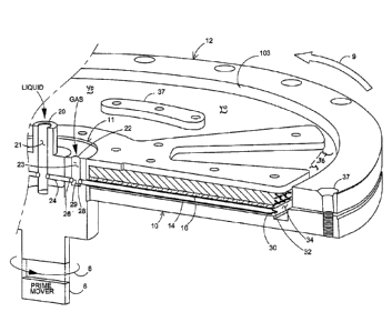
One embodiment of the present invention includes a flat aluminum disc or back
plate 10 (Fig. I) with two shallow generally radial pockets milled into one
side, These
milled pockets are sealed into hydraulic passages by the gasket 16 and a
polyearbonatc
cover plate is placed over top of the gasket (not shown). A plurality of
capillary tubes
10 (see tube 14) may be disposed or formed on the disc. The disc is secured
by an
aluminum clamp ring and face washers and through-bolted (see bolt hole 37,
rig. 1) to
the aluminum back plate 10, A cent -al brass hub is bolted to the aluminum
back plate 10.
The brass hub, holding emulsification device ii. is machined to provide a
sealed liquid
inlet 20 on the front side, and a sealed pressurized gas harvest port 60 (Fig.
2), on the
rear. Capillary compression tubes 14 are mounted in the channels in the milled
pockets
on the aluminum back plate 10 in a nominally radial orientation with inlets 28
at the
proximal ends (near the axis of rotation) set inside the ambient gas inlet 22,
23 and just
distal to the emulsion ejector 26 exit. Liquid is fed into port 20 and is fed
through
channel 24 and is ejected from outlet port 26. The liquid jet then mixes with
the gas in
venturi jet region 29 to form a venturi generated emulsification of gas and
liquid WhiCh
is injected into capillary port 28.
Nominally pressurized water (or other liquid) is introduced into the sealed
liquid
delivery port 20, Two small jet ejector tubes, one on each side, see ejector
port 26, carry
liquid from the sealed liquid delivery port 20, 21 and form liquid jets aimed
at the
radially inboard ends 28 of the capillar3/ dimension compression tubes 14. The
liquid jet
crosses a gap 29 which is open to a gaseous environment. The venturi effect
created by
the liquid jet as it enters the entrance of the compression tube 14 traps and
entrains small
bubbles of gas which then form an emulsified gas-liquid mixture, and, when in
the
CA 03001809 2018-04-10
WO 2016/061164 PCT/US2015/055427
11
capillaries 14 form a bubble train inside the compression tubes 14. See FIG.
11 as an
example.
The pressurized gas-liquid emulsion mixture; at the radially outboard ends of
the
compression tubes 14, exits the compression tube outlet port 30, whereupon the
newly
unconstrained gas fraction, pressurized gas (see FIG. 12), of the compressed
gas-liquid
emulsion Mixture is immediately subject to buoyancy and floats towards the
center of
rotation in the form of bubbles, separates from the liquid fraction (see
outermost
peripheral collection region 110 in FIG. 12) and is trapped inside the
compressed gas
chamber 40 (FIGs. 1 and 12). See flow 113 of compressed emulsified gas liquid
in Fig.
12. The liquid fraction of the emulsion mixture in region 110, FIG. 12,
exiting the
radially outboard ends 30 of the compression tubes 14, being denser than the
gas fraction
in this radially constrained emulsion (in region 110, emulsion is constrained
by
centrifugal forces), is forced to the radially outboard hydraulic limits of
the milled
pockets in liquid drain column space 105 the aluminum back plate 10 and into
the liquid
drain port 116, FIG. 12. As pressurized gas 115 (FIG. 12)fills the pressurized
gas Storage
chamber 40 (FIGs. 1, 12), the liquid level of the separated liquid in the
pressurized gas
storage chamber, 40 is forced in the radially outward direction to peripheral
collection
region 110 by the building presSure (FIG. 12) against the inboard surface 103
of the
peripheral wall of gas collection region 40. Separated liquid in liquid drain
collection
region 105 (Ma 12) passes through the device and leaves through the drain/blow
'off
port 116 and up to the drain/bluff where it is released from the gas
compressor.
Drain/blow off port 116, FIG. 12, is open to atmosphere at a hydraulically
higher
elevation than the liquid pressure seal level in liquid drain column space
110, and the
radial elevation difference; combined With the angular velocity, liquid
density, and gas
density, determines the maximum pressure the device will generate. Pressurized
gas 115
continues to be captured in the Compressed gas chamber 40, increasing in
volume and
forcing the liquid level in drain collection space 105 inside the chamber in
the radially
outward direction until reaching the level of the liquid seal level 110 at
which point the
CA 03001809 2018-04-10
WO 2016/061164 PCT/US2015/055427
12
gas trapped in the compressed gas chamber 40 creates a gas blow-off condition,
wherein
gas bubbles escape under the liquid seal level arrow 117, FIG. 12, on the
radially outward
side and then float radially inward to the drain/blow off port 116 where the
excess gas
pressure is released to atmosphere, acting as a protective pressure release
mechanism that
prevents the compressor from exceeding its maximum pressure limit. Pressurized
gas
115 in the compressed gas chamber 40 is harvested through the pressurized gas
harvest
ports 52a (FIG. 2, 12) in the aluminum back plate 10 and brass hub or
:emulsification
device 11, Where it exits the device through a pressurized rotary seal port 60
via passages
54a, 56, 60 ,(FIG. 2).
In one embodiment, a single layer of capillary tubes 14 is disposed as a disc.
In
other embodiments, stacked discs are used to compress the gas.
Figure 1
diagrammatically illustrates a single capillary tube 14, and only graphically
shows stacks
of tubes. Each disc carries a plurality of capillary passages 14 thereon. In
one
embodiment, these Capillary passages 14 are laid onto a back plate and a
gasket 16 is
placed over atop the plurality of capillary passages 14 generally disposed
radially on back
plate 10. In one embodiment, back plate 10 is aluminum and the gasket is
interposed
between layers of capillary passages 14. A polycarbonate cover plate (pot
shown) on the
'tubes over the gasket is also used.
The capillary passages need not be in a direct radial line (as "spokes") but
may
be generally radially positioned, tangential to the axis of rotation (see
prime mover 6 and
rotation 8 and disk rotation 9). Figures 19 and 20 show substantially radial
capillary
tubes Or passages. Fig. 18 shows that capillaries 14 are tangential are
tangential to the
emulsification device 11. Input ports 28 for capillaries 14 are shown. The
system rotates
in direction 151 about rotational axis 150. The output end of the capillaries
are near
radially inboard wall 103 of the disc 12. Fla 20 shows that the capillaries 14
are curved
in the direction Of rotation 151. Tangentially oriented capillaries in FIG, 19
are generally
curved or displaced towards the direction of rotation 151, Therefore, the
continuously
curved capillaries 14 in FIG 20 may be displaced in the direction of rotation
as shown
CA 03001809 2018-04-10
WO 2016/061164
PCT/US2015/055427
13
in FIG. 20 (the capillary output ports trailing the direction of rotation) or
the continuously
curved Capillaries may be displaced opposite the direction of rotation (the
capillary
output ports leading the direction of rotation)(not shown in the Figures). In
both all
these Configurations, FIGs, 1, 18, 19 and 20, the capillaries are
"substantially radially
positioned."
Further, the capillary passages may be axially stacked in the disk in an
offset
manner and the main longitudinal body of the capillaries may be curved either
in the
direction of rotation 9 or counter the direction of rotation 9. The Stacked
tubes are only
graphically shown in FIG. I. Figure 18 Shows a disc 160 with a plurality of
generally
radial eapillaty tikes. The radially inboard emulsification device 11 is
disposed in space
162. Discs are retained together by attachment systems operative with passages
166.
The discs are keyed to each other with keyways 164 operative with key elements
(not
shown) on adjacent discs. The key elements fit within keyways 164.
An emulsification device 11 is radially inboard with respect to the capillarY
passages 14. Liquid is injected or otherwise directed into port 20 of the
emulsification
device 11 and the liquid passes through axial channel 21: The liquid is
ejected via
generally radial channel 24 and ejected out of output port. 20. The U.S.
patent application
Serial No. 14/280,780 discloses several types of emulsification devices for
Centrifugal
gas compressors..
Gas is fed into the emulsification device 11 via port 22 and passes through a
gas
port 23. When the ejected fluid leaving exit port 7:0 and intersects the gas
in region 29,
a venturi jet effect is created thereby creating An emulsified liquid ¨ gas
mixture Which
is forcibly directed into input port. 28 of capillary 14. See Fig. 11, As
described in detail
later, the gas in this emulsified liquid ¨ gas mixture is compressed as it
passes from a
radially inboard proximal region to a generally radially outboard distal
region at capillary
exit port 30.
In the illustrated embodiment, to create substantially radially outboard flow
of the
compressed gas ¨ emulsified liquid mixture (stated otherwise, limiting
substantially
CA 03001809 2018-04-10
WO 2016/061164 PCT/US2015/055427
14
radially inboard flow), the terminal exit end 30 of capillary 14 has a duck
bill one-way
valve 32. After the compressed gas ¨ liquid emulsified Mixture (the gas being
compressed due to increasingly greater centrifugal forces acting thereon)
exits port 30
and valve .32, it enters a generally arcuate peripheral container space disk
region 34
leading to arcuate peripheral disk region 36.
A plurality of one-way duck-bill valves at the ends of a number of capillaries
is
graphically shown in Figure I (not numbered) indicating that the disc is
formed with a
plurality of capillaries formed as discs which discs are stacked one atop
another to form
stack 12. For more details of stacked capillary discs, reference is made to
serial number
14/280780,
The arcuate peripheral disk region 34, 36 has several collection spaces
including
a 'compressed gas collection Space 40 generally radially inboard in the
compressor from
a compressed gas ¨ liquid emulsified mixture region 36. See also emulsified
mixture
collection region 110 in FIG. 12. Gas Collection region 40 is formed by disk
plate
separators having leg spacers 33, 35 and disk plate separation islands 37 or
cover plate
washers,
Figure 2 diagrammatically illustrates compressed gas drains 52a, 54a, 56 from
the
compressed gas collection space 40. ()nee Compressed gas bubbles emerge from
the
emulsified compressed gas ¨ liquid mixture in arcuate peripheral disk region
36 (See
emulsified mixture collection region 110 in FIG. 12), the gas fills compressed
gas space
40 and ultimately this compressed gas exists space 40 via gas drain 52.a. The
compressed
gas flow is shown by arrow 50 in Figure 2. The Compressed gas drain leads to
an axial
passage 54a and then a radial passage 56 to a central axial gas output port or
passage 60.
Compressed gas is drawn off from gas Collection Space 40 via gas drains 52a,
52b,
passages 54a, 54b, and axial passage 58. Blind holes are not shown in these
drawings.
Figures 3, 4, 5, and 6 diagrammatically illustrate the operation of the flow
restriction elements to achieve one-way flow from radially inboard portions of
capillary
tube 14 to a radially outboard tube port 30. Although Figure 1 shows a duck-
bill one. way
CA 03001809 2018-04-10
WO 2016/061164 PCT/US2015/055427
valve 32 at output port 30 of capillary 14, the one way or flow restriction
element can be
placed at any designed location in the capillary tube. One or more one-way
valves may
be disposed along the capillary tubes. Different gasses, with different
solubilities for
different liquids may require one or a plurality of one way flow restriction
elements to
5
achieve the one way flow of compressed gas-liquid emulsified mixture through
the
capillary tube 14. The drawings herein are only illustrative of the location
and type of
one-way flow or rectifying flow valves.
One way flow of the emulsified liquid gas is achieved by limiting
substantially
radially inboard flow, which outboard flow causes the gas bubbles in the
emulsified
10
mixture to compress as the liquid slug of the mixture moves radially outward
due to
centrifugal force. In general, the liquid in the emulsified mixture is
substantially
incompressible as compared with the gas bubbles.
The term "compressed gas-liquid emulsified mixture" and other similar terms
are
meant to encompass compressed gas bubbles entrained in a liquid.
15
Figure 3 diagrammatically illustrates the forces on a gas bubble as it passes
through capillary tube 14. Tube 14 has a proximal end 62 which is radially
near the axis
of rotation 9 of the rotating system. Capillary 14 generally has a
longitudinal axis 67.
Centrifugal flow CF in direction 63 acts on the liquid thereby pushing bubble
60 radially
outward in direction 61. However, the buoyant force 13F as shown by arrow 65
counteracts the centrifugal force CF and acts to move the bubble radially
inward. If the
buoyant force BF is larger than the centrifugal force CF. the entrained bubble
in the
liquid will move radially inboard and the gas bubble 60 will not be
compressed, By
limiting and restricting the inboard flow of the emulsified mixture, the gas
bubbles can
only flow radially outward along with the liquid slug forming a compressed gas-
liquid
emulsification in the capillary tubes. As the entrained gas bubbles in the
liquid reach the
radially outward portion of the rotating disk, the gas bubbles compress. This
compressed
gas-liquid emulsified mixture releases the compressed gas in container disc
space 40.
CA 03001809 2018-04-10
WO 2016/061164
PCT/US2015/055427
16
In Figure 4; capillary tube 14 has a radially inboard port 62. At the radially
inboard region 69, a gas bubble 60 forms in the emulsification. One way valve
64
(diagrammatically illustrated) prohibits backflowof the entrained gas bubble
and liquid.
Thei'eforp, the liquid holding the gas bubble 60 cannot pass radially inboard
towards
entrance port 62 because such flow is blocked by the diagrammatic one-way
valve 64.
Radially out board flow is promoted in distal region 71 of capillary tube 14.
Figure 5 diagrammatically illustrates that the one-way valve is a flap valve
or a
swing valve. In either ease; Swing valve 68 acts as a mechanical check valve
which
prohibits liquid and the entrained gas bubbles 66 from moving radially inboard
or
towards input port 62 of capillary 14. The flap or swing element 68 of the
Valve moves
in the direction 65.
Figure 6 diagrammatically illustrates that a duck bill valve 70 that can be
disposed at some intermediate position between input port 62 of capillary 14.
This valve
is also at distal region 36 or the terminal end 30 of the tube. See Figure 1.,
Figure 7A diagrammatically illustrates a swing valve or a tilt disk valve
having
a pivoting flap Member 72. A biasing element is diagrammatically illustrated
as a spring
element 76 in Figures 7A, 713 and 7C. However; any type of biasing element
could be
used Such as a spring, compression member, compressible plug or pin, etc. The
swing
element 72 may be flexible such that the element creates its own biasing force
(wherein
spring 76 is illustrative Of the push-back force created by the structural
features of swing
panel 72). The swing element 72 fits against seat 74 formed at the designed
location of
Capillary 14a,
Figure 713 shows a lift valve having a valve element 77 biased by biasing
element
76 such that the lift element 77 seats against valve seat 74 in capillary 14b.
Figure 7C diagrammatically shows a ball check valve having ball element 78
which seats against valve seat 74 in capillary 14e:
One-way valves are sometimes identified and discussed in the literature as
rectifying flow valves. A rectifying flow valve permits flow in only one
direction and
CA 03001809 2018-04-10
WO 2016/061164 PCT/US2015/055427
17
blocks flow in the opposite direction. For example, rectified water flow is
achieved on
a macro scale When portions of waves crash over barrier walls. The wave
passing over
the wall is rectified unidirectional flow.
Figure 8 diagrammatically illustrates an emulsification device 11 which is
disposed at a radially inboard position (see Figure 1) with respect to other
items on the
rotating disk found on back plate 10. Several different types of
emulsification devices for
gas compressors may be used.
In Figure 8, gas is fed into input port 22 o f emulsification device 11 and,
in region
29, a venturi jet is created by liquid ejected, from output port 26 into
venturi jet region 29.
The emulsified gas ¨ liquid mixture is then forced into inlet port 28 of
capillary tube 14.
At the radially outer end 30 of capillary tube 14, a duckbill one-way valve 32
limits
radially inboard flow and promotes radially Output flow of the compressed gas
¨ liquid
emulsification mixture. The compressed gas emulsification is captured in space
34 in
FIG. 1.
Figures 9A and 9B diagrammatically illustrate duckbill valve 32 which is
mounted in or on capillary 14. As an example, dimension "a" is about 1.7 min,
length "b"
is about 2.5 mm, and base dimension "e" is about 0.5 mm. In Figure 9B, the
length "d"
is about 2.2 mm and the bill portion of the valve is slightly more than One
half the length
A discussion of creating, enforcing and enhancing unidirectional distal
emulsion
flow follows. centrifugal force, acting on the mass of the slugs of liquid
between bubbles
mass X angular velocity squared X radius), drives the gas bubbles radially
outward (distally) until the buoyant forces from the bubbles acting radially
inward
(proximally) equal or exceed the centrifugal forces, at which point a total
rejection of
new liquid from the jet ejector tubes occurs.
In one embodiment, the bubble train (see FIG, 10) acts similarly to a multiple
mass-spring-mass-spring system with an inherent resonance, where the
incompressible
liquid slugs act as the mass and the compressible (flexible) gas bubbles as
the spring.
CA 03001809 2018-04-10
WO 2016/061164 PCT/US2015/055427
18
This resonance combines With the buoyant forces and centrifugal forces acting
on the gas
and liquid fractions of the emulsion to create an oscillatory behavior in
bubble train
which effectively restricts or even blocks the distal flow of liquid or gas in
the
compression capillary tubes within certain angular velocity ranges.
The device performs a given amount of work to push a given gas bubble within
Nibble train from the proximal to the distal end Of compression tube 14. Any
movement
by said bubble in the proximal direction is lost work and lost productivity ¨
lower
efficiency ¨ by the device. Creating, enforcing and enhancing distal
Unidirectional
emulsion flow (bubble train) in compression tube :14 is therefore critical to
efficient
device operation.
The present invention can be modified to utilize a number of methods,
individually or in combination, to create, enforce, and enhance distally
oriented
unidirectional emulsion flow (bubble train) in the compression tubes 14.
Figure 10 diagrammatically shows an early bubble formation $4 at proximal and
28 of capillary 14 and, at a radially distant position in the tube, a fully
formed gas bubble.
Force lines 86, 88 and 90 represent the mass-spring-Mass oscillation of the
hydraulic
system caused by the liquid slugs passing through capillary 14, those slugs
being
generally separated by gas bubbles. Mechanical impedance is found in a mass ¨
Spring
mass systems. In physics; it is the 'ratio of the force on a system undergoing
simple
harmonic motion to the velocity of the particles in the system. Stated
otherwise,
mechanical impedance is a measure of how much a structure resists motion when
subjected to a harmonic force. it relates forces with velocities acting on a
mechanical
system. The mechanical impedance of a point on the structure is the ratio of
the force
applied, at that point to the resulting velocity at that point. See http:
//www:
cqe.northwestermedu/sk/EA3/E:A3_weak_couplc.pdf; and hap:// WWW,
hk SIV,COMidoCi I 7 -1 7 9 .pdf; a n d
http://
diedonary.reference. com/browse/mechanical-impedance; https;//
en.wikipedia.orgiwiki/Mechanical_impedance; and hap:// www.
CA 03001809 2018-04-10
WO 2016/061164
PCT/US2015/055427
19
engineering uesb. edui¨paden/ME104/notesiPhasor-analysi s-of-mechanical-
systems-re
v-A.pdf
Scientific literature also discusses hydraulic impedance. For example in an
article
entitled "Study on the Hydraulic Impedance of Surge Tank", the discussion
centers
around a calculation of hydraulic impedance of a surge tank, both a simple
tank and a
throttled tank. The effects of a surge tank on the hydraulic vibration of
pressurized
conveyance system of hydropower is the subject of the study. The investigation
shows
that the attenuation factors Of System decrease if the hydraulic resistance
coefficient of
the surge tank increases. The hydraulic impedance of a hydraulic turbine has
almost no
effects on the frequency of the system which are Close to the even order
frequencies of
pipe. See publication it:11HE Mechanic Automation and Control Engineering
(MACE),
2011 Second International Conference on Date of Conference: 15-17 July 2011
Page(s):2624 - 2627 Print ISBN: 978-1-4244-9436-1, author: Wen-tali) Feng
Therefore, the mass - spring - mass oscillatory action of the bubble-liquid
slug
train represents hydraulic impedance promoting unidirectional distal flow
created in the
Capillary tubes. The impedance of the tube is the resistance to proximal or
back flow of
the bubble-liquid slug train. Stated otherwise; the compressed gas - liquid
emulsion
Mixture passes through the capillary tubes in one direction radially outward
towards the
distal tube end,
With respect to radially Outward flow of the compressed gas ¨ liquid emulsion
through the: capillaries 14, it is believed that the bubble train Shown in
Figure 10 is
similar to multiple mass ¨ spring ¨ mass ¨ spring systems with and inherent
residence.
The generally incompressible liquid slugs act as the mass and the
compressible, that is
generally flexible, gas bubbles act as springs in capillary 14. The
oscillating behavior
effectively restricts flow of emulsified compressed gas ¨ liquid mixture
through the
compression tubes With respect to Figure 10, these forces 86, 88, 90 are
acting upon all
the bubbles in capillary 14, and are not limited to the illustrated last three
or four bubbles
at the distal end of the tube.
CA 03001809 2018-04-10
WO 2016/061164 PCT/US2015/055427
Several methods ,for creating distally oriented unidirectional emulsion flow
are
discussed below. Mechanical checking Mechanisms are One class of device that
can be
added to the capillary compression tubes 14 to create complete unidirectional
flow. This
class includes swing-check, ball type, tilting disc type, in-line, lift-type,
flap-type, and
5
duckbill type devices, among others. Mechanical checking mechanisms can be
placed
anywhere along the length of compression tube 14, individually or serially, to
create a
condition wherein proximal emulsion -flow in bubble train is impossible.
One
embodiment of this concept is Seen in duck-bill check valves 32 (Fig. 1) at
the radially
outboard ends 30 of the compression tubes 14.
10
Enforced unidirectional flow in this device is also accomplished by using the
following two methods.
Liquid ejectors in the emulsification device ii provide the considerable; but
incomplete; one way checking effect of distally directed kinetic energy via
the inertia of
ejector jet streams directed at the inlet ends or interim locations along the
length of the
15
capillary compression tubes. The distally oriented inertia (velocity times
mass) of the
liquid mass counteracts the proximally oriented buoyant force of gas bubbles
in the inlet
portion 28 of compression tube 14 and aids to maintain distally oriented
emulsion flow.
Proximally oriented emulsion flow Or complete flow blockage can still occur
once the
reverse pressure exceeds the maximum pressure ratio of the ejector, but the
liquid
20
injectors (venttiri set 26, 28, 29), in combination with other methods, act to
reinforce the
centrifugal forces acting on the liquid slugs pushing the gas bubbles distally
in bubble
train.
Tapered compression tubes (see FIG. 16A) are compression tubes 14 with
diameters that decrease along their length moving from proximal end to distal
end. In the
case of isothermal compression, gas volume decrease is directly proportional
to Change
in pressure. AS an example; air being entrained in bubble train enters
compression tube
14 at the proximal end and forms a full diameter bubble., sealing the liquid
on either side
of it. The pressure on the emulsion quickly increases as the bubble moves in
the distal
CA 03001809 2018-04-10
WO 2016/061164
PCT/US2015/055427
21
direction, with corresponding decrease in volume. The radius of a sphere
decreases by
the cube root of its volume, thus the bubble shrinks dramatically shortly
after entering
the tube and begins to pull away from full contact with the compression tube
14 walls but
shrinks more slowly as it proceeds further distally in the compression tube.
As long as
the bubble maintains full diameter contact with the wall of the capillary
tube, buoyancy
¨ the tendency of liquid to find its own level -- cannot act, however, if the
liquid is
permitted to slip past the bubble, buoyancy acts and the bubble experiences
proximal
movement relative to the liquid. The buoyancy of a bobble drops in proportion
its
reduction in volume and eventually is reduced to a degree that the bubble is
no longer
capable of developing a sufficient rate of rise through the liquid to overcome
the distally
oriented liquid velocity. Tapering compression tube 14 (F1G. 16A) is thus
enforcing
distally oriented unidirectional emulsion flow4iS long as the tube Wall
maintains ftill
contact with the bubble. The rate of the compression tube 130 taper must be
specifically
engineered to the design Operating parameters of the device, and is primarily
determined
by inner and outer diameter of rotation, liquid density; gas density, and
rotational
velocity.
An example calculation of the internal diameter of a tapered capillary
compression tube at a specific radius is included as Fig. 17.
Methods for enhancing distally oriented unidirectional emulsion flow follow.
Bubble buoyancy is the primary force opposing distally oriented emulsion
inertia in a
rotating frame of reference. It counteracts the liquid slug inertia as the
buoyancy vector
is always opposite the inertia vector of the slug and is only evident when
liquid is
permitted to pass around the bubble and displace the gas volume as it moves.
Bubbles
smaller in diameter than capillary tube 14 will permit liquid to pass around
them in the
distal direction, causing proximal movement of the bubble relative to the
liquid, and act
to resist liquid flow in the distal direction through friction.
The: gas fraction of the gas/liquid emulsion entering capillary compression
tube
14 is at its highest just distal of the proximal inlet 28 (see proximal bubble
formation in
CA 03001809 2018-04-10
WO 2016/061164
PCT/US2015/055427
22
FM. 10). Using the Boyle's Law, the gas fraction of the emulsion decreases as
it
becomes compressed Wihen the emulsion is forced distally through compression
tube 14,
giving the emulsion a higher unit density taking into account centrifugal
forces. The
acceleration and resulting inertia of the liquid mass as it moves through
capillary
compression tube 14, is the primary motive force driving the gas fraction to
the distal
ends and thus compressing it.
Figure 11 diagrammatically illustrates capillary tube 14, and, in distal mid-
region
101 of tube 14, a series of bubbles and, in the downstream, distal region 103
and beyond,
a series of other bubbles 105, 107 and 109. These further downstream bubbles
107, 109
become smaller due to compression of the gas. The compressed gas ¨ liquid
emulsified
mixture enters arcuate peripheral container space disk region 36 as discussed
in
connection with Figure 1 and as discussed later in connection with Figure 12.
The
formula being:
Centrifugal Force equals in co w r.
Adjacent to capillary 14 is a force graph showing, along the ¨ axis the bubble
buoyancy force, which diminishes as the, bubble moves radially from an inboard
position
to an outboard position in capillary 14, This bubble buoyancy curve is
generally
contrasted with the effective veight and generally constant volume of the
liquid portion
in capillary 14. The "effective weight" of the liquid slug being a function of
the
centrifugal force applied thereto. The entire system (capillary tube 14 and
the traveling
emulsified gas ¨ liquid mixture) is effected by the rotational force or
centrifugal force
shown in Figure 11.
Centrifugal force, acting on the mass of liquid slugs between bubbles drives
the
gas bubbles radially outward, that is in a distal direction, until the buoyant
forces from
the bubbles acting radially inward (that is proximal force) equal or exceed
these inertial
and centrifugal forces, at which point total ejection of new liquid from the
jet ejector
tubes 24, 26 (Figure 1) occurs.
CA 03001809 2018-04-10
WO 2016/061164 PCT/US2015/055427
23
Figure 12 diagrammatically illustrates a plan view of the disc. Liquid is
ejected
from the emulsification device 11 and from liquid ejection port 26. In space
29, which
is flooded with gas, a venturi jet is created \\hereby an emulsified gas ¨
liquid mixture
enters input port 28 of eapil tiny tube 14. As the entrained bubbles move
radially outward,
the gas is compressed and the compressed gas ¨ liquid emulsified mixture exits
the
radially distal terminal end 30 of capillary tube 14 as shown by arrow 113.
Since the
entire system is spinning, the emulsified compressed gas ¨ liquid mixture is
initially
disposed along the interior wall surface 103 near the output of the capillary
tube. Highly
compressed gas leaves the mixture in peripheral region 110, leaving a liquid
fraction in
region 110. The outer reaches of arcuate peripheral container space region 36
is
peripheral collection region 110. Space 36 shown in Figure 1 lies along the
radially
inboard wall surface 103 of the disc stack. Compressed gas bubbles emerge from
the
compressed gas¨ liquid emulsified mixture forced against interior wall 103 in
the region
110 near outlet of tube 14 and the non buoyant compressed gas bubbles separate
from
this mixture flooding the larger gas containment space 40, In Figure 12, this
is shown by
random gas arrows 115. The gas exits arcuate container space 40 at gas exit
port 52a. See
also Figure 2.
As pressurized gas 115 fills the arcuate pressurized gas storage chamber 40,
the
liquid level in peripheral space 110 is forced in the radially outward
direction and into
liquid column drain region 105 by the building pressure Separated liquid
passes
through the device and leaves through a drain or blow off port 116 where it is
released
from the compressor. Drain and blow off passage 116 is open to the atmosphere
at a
hydraulically higher level than the liquid pressure seal level at the radially
outboard side
of peripheral collection region 110. The water column in drain space 105
determines the
95 maximum pressure that the compressor device will generate. Pressurized
gas 115
continues to be captured in the compressed gas chamber 40, increasing in
volume and
forcing the liquid level (in defined space 110) to push liquid (see arrow 117)
inside the
chamber blow' off space 105 until reaching the point wherein the gas trapped
in the
CA 03001809 2018-04-10
WO 2016/061164
PCT/US2015/055427
24
compressed gas chamber 40 creates a gas blowoff condition Wherein gas bubbles
escape
under the liquid seal (see bubbles in arrow 117) on the radially outward side
of peripheral
space 105 and then float radially inward to the drain blowoff port 116 where
the excess
gas pressure is released to atmosphere, acting as a protective pressure
release mechanism
that prevents the gas compressor from exceeding its maximum pressure, limit.
Compressed gas forced into drain column 105 is released to the atmosphere,
acting as a
protective pressure release mechanism that prevents the compressor from
exceeding its
Maximum pressure limit. Pressurized gas 115 in the compressed gas chamber 40
is
harvested through the pressurized gas harvest ports 52a in the aluminum
backplate 10
(Figure 1, 2) and ultimately through the brass radially inboard hub where the
compressed
gas exits through a pressurized rotary seal port.
Figure 13 diagrammatically shows capillary tube 14 having a tail end segment
120 which is angularly displaced in the direction of rotation 9, The tail end
segment in
FIG, 13 is bent More than 90 degrees from the adjacent, axial centerline of
the capillary
tube. Figure 14 shows capillary tube 14 with a tail end segment 120 angularly
displaced
about 90 from the generally longitudinal centerline 119 of capillary 14, See
angular
displacement :121 in FIG. 14. The tail end segment may be bent and may lay
against wall
103 of container space, 40, See FIG. 1 and diagraminatie line 103 in FIG. 13.
The
angular displacement is generally identified from the substantially radial
axial centerline
123 of the capillary tube, upstream of the bent tail end segment.
Returning to Figure 13, the tail end segment 120 generally follows the inboard
Surface plane 103 of the spinning disk. See Figure 1, With the use of
angularlydiSplaeed
terminal end segments, radially inboard flow is limited and radially outward
flow is
promoted due to the Coriolis force developed 41 the terminal and SegmentS. In
phySies,
the Coriolis effect is a deflection of moving objects when the motion is
described relative
to a rotating reference frame. In a reference frame with clockwise rotation,
the deflection
is to the left of the motion of the object; in one with counterclockwise
reddish rotation,
the deflection is to the right. The Coriolis effect is in effect whereby a
Mass moving in
CA 03001809 2018-04-10
WO 2016/061164
PCT/US2015/055427
a rotating system experiences a force (the Coriolis force) acting
perpendicular to the
direction of motion and to the axis of rotation. On earth, the effect tends to
deflect
moving objects to the west in the northern hemisphere and to the east in the
southern
hemisphere and is and is important in the formation of cyclonic weather
systems,
5 Otherwise, the Miriam Webster dictionary defines Coriolis force as an
apparent force that
as a result of the Earth's rotation deflects moving objects (as projectiles or
air currents)
to the right in the northern hemisphere into the left in the southern
hemisphere.
The Coriolis effect in the tail end segments increases the separation of the
entrained compressed bubbles against the side walls of the capillary tubes 14
thereby
10 compelling the bubbles to be ejected front the output port of the tube.
Emulsion acceleration only occurs in the radial section of compression tube 14
and brings the emulsion to a maximum velocity approaching the radial speed of
aluminum back plate 10 (FIG. 1) at tail end bend 120 (Fig. 13).
The compressed gas - liquid emulsion mixture captured in capillary compression
15 tube 14 changes direction when it reaches the bend in the tail end. An
empirical study has
determined that a tail end bend when made at least normal to the plane of
rotation, such
that the outer radius of tail end bend reaches the outer design radius of
compression,
creates a condition which enhances and assists distally oriented emulsion flow
The tail
end of compression tube 14 can lie flat against the radially outer, inner wall
of
0 pressurized storage chamber or can be bent further than 90', back towards
the axis of
rotation (up, in a rotating frame of reference).
The direction that tail end bend faces impacts the performance of compression
tube 14. The tail end bends in the plane of rotation and trailing the
direction of rotation
performed the best, and bends in the plane of rotati on but leading the
direction of rotation
25 pertbrmed poorly, if at all. Tad end bends in either direction parallel
to, but offset from
the axis of rotation showed improved performance over compression tubes 14
with no
tail end bend.
CA 03001809 2018-04-10
WO 2016/061164 PCT/US2015/055427
26
Figures 15, 16 and 17 diagrammatically illustrate another structure to
restrict
radially inboard flow of the entrained gas bubbles in the liquid and promote
radially
outward flow of the compressed gas in the gas ¨liquid in emulsified mixture.
Figure 16A
diagrammatically, illustrates that the capillary tube 130 can be tapered from
its radially
inboard port 28 to its radially distal port 30. In other words, at example
tube length 0.5,
the diametc,r or the interior passage cross-sectional dimension of the
capillary tube is
much larger as compared to example tube length distance 3.5 which has a much
smaller
cross-sectional passage area.
Figure 16B shows that capillary tube 132 has a generally constant or uniform
cross-sectional dimension extending from input port 28 until the longitudinal
section
134. In section 134, the cross-sectional dimension of the capillary tube
narrows until the
tube reaches distal longitudinal section 136, At that point, the capillary
tube has a
constant, but a smaller, cross sectional passage flow. This leads to output
port 30.
FIG, 16 graphically illustrates the change in the radius of a capillary tube
as
compared with the length of the capillary tube.
Figure 18 shows a disc 160 with a plurality of generally radial capillary
tubes.
The radially inboard emulsification device 11 is disposed in space 162. Discs
are
retained together by attachment systems operative with passages 166. The discs
are
keyed to each other with keyways 164 operative with key elements (not shown)
on
adjacent discs. The key elements fit within keyways 164.
Figures 19 and 20 show substantially radial capillary tubes or passages. Fig.
18
shows that capillaries 14 are tangential are tangential to the emulsification
device 11.
Input ports 28 for capillaries 14 are shown. The system rotates in direction
151 about
rotational axis 150. The output end of the capillaries are near radially
inboard wall 103
of the disc 12. FIG. 20 shows that the capillaries 14 are curved in the
direction of rotation
151. Tangentially oriented capillaries in FIG. 19 are generally curved or
displaced
towards the direction of rotation 151. Therefore, the continuously curved
capillaries 14
in FIG, 20 may be displaced in the direction of rotation as shown in FIG, 20
(the capillary
CA 03001809 2018-04-10
WO 2016/061164
PCT/US2015/055427
27
output ports trailing the direction of rotation) or the continuously curved
capillaries may
be displaced opposite the direction of rotation (the capillary output ports
leading the
direction of rotation)(not shown in the Figures). In both all these
configurations, FIGs.
1, 18, 19 and 20, the capillaries are -substantially radially positioned."
The claims appended hereto are meant to cover modifications and changes within
the scope and spirit of the present invention. What is claimed is;