Note: Descriptions are shown in the official language in which they were submitted.
TRUCK-MOUNTED MATERIAL SPREADER
Field of the Invention
The present invention relates generally to a material spreader mountable to
a vehicle for conveying and spreading material.
Background of the Invention
Material spreaders are commonly used for carrying and spreading
materials, such as salt or sand, on surfaces such as sidewalks, parking lots,
driveways, roadways and the like. Material spreaders typically include a
hopper
for storing the material, a frame for supporting the hopper and attaching it
to the
rear of a vehicle, and a spreading mechanism for distributing the material.
Material spreaders can be attached to a vehicle in a variety of ways. For
example, the material spreader can be attached to a rear portion of a vehicle
by
coupling the frame to a trailer hitch on the vehicle. Alternatively, the
vehicle may
be modified by attaching mounting brackets to the rear bumper for example, by
drilling holes in the bumper and attaching the mounting brackets by bolts. The
material spreader can include corresponding mounting brackets for mating with
the mounting brackets on the bumper to connect the material spreader to the
vehicle.
Summary of the Invention
The present invention provides a material spreader that is attached to the
vehicle by connecting it to a vehicle hitch such that a hopper rests on top of
a rear
bumper of the vehicle. A tie down on the material spreader provides a clamping
action between the hopper and the vehicle hitch to hold the material spreader
on
the rear bumper of the vehicle with a clamping force. The material spreader
can
be easily attached to and removed from a vehicle without the need for
extensive
and/or permanent vehicle modifications.
More particularly, the material spreader is mountable to a rearwardly
projecting bumper of a vehicle for conveying and spreading material. The
material
spreader includes a hopper for holding material to be spread and a frame that
1
CA 3002291 2018-04-20
supports the hopper and has a forwardly projecting hitch mount configured for
coupling to a rearwardly projecting hitch receiver on the vehicle. A support
has an
underside for resting atop a top surface of the bumper and the support is
movable
vertically relative to the frame. A tie down is connected between the support
and
the frame for urging the support and the hitch mount towards one another to
effect
a clamping action on the receiver and the bumper. In a preferred embodiment,
the support is unitary with the hopper.
The material spreader also provides a unique pivoting connection for a
hopper lid that enables/facilitates the loading of the hopper from different
sides of
the vehicle.
More particularly, the material spreader includes a hopper for holding
material to be spread and a lid for closing an open top of the hopper. The
hopper
has first and second sides and first and second sets of laterally spaced apart
hopper hinge elements. The lid has first and second sets of laterally spaced
apart
lid hinge elements respectively configured for connection to corresponding
first
and second sets of hopper hinge elements. The hinge elements of a first one of
the corresponding sets are releasable to allow the lid to pivot upwardly to a
first
open position about the hinge elements of a second one of the corresponding
sets. The hinge elements of the second one of the corresponding sets are
releasable to allow the lid to pivot upwardly to a second open position about
the
hinge elements of the first one of the corresponding sets. In a preferred
embodiment, one set of hinge elements for each corresponding set of hinge
elements are laterally deflectable to release the corresponding set of hinge
elements.
According to another aspect, the material spreader includes a spinner, an
auger for feeding material from the hopper on to the spinner, and a drive
assembly for driving the auger and the spinner. The drive assembly includes a
motor, a drive shaft connected at opposite ends to a motor and a spinner
whereby
the spinner operates at the same rotational speed as the motor, and a gear
reduction assembly connected between the auger and the drive shaft for driving
the auger at a slower rotational speed that the spreader.
2
CA 3002291 2018-04-20
In one aspect, there is provided a material spreader mountable to a rearwardly
projecting bumper of a vehicle for conveying and spreading material, the
vehicle
including a rearwardly projecting hitch receiver, the material spreader
comprising: a
hopper for holding material to be spread; a spinner for distributing material
supplied
from the hopper; a drive assembly for driving the spinner; a frame supporting
the
hopper and having a forwardly projecting hitch mount configured for coupling
to the
rearwardly projecting hitch receiver of the vehicle; a support having an
underside for
resting atop a top surface of the bumper, the support having a portion thereof
spaced
apart from and movable vertically relative to the frame; and a tie down
connected
between the support and the frame for urging the support and the hitch mount
towards
one another while said portion of the support and the frame remain in spaced-
apart
relationship to effect a clamping action on the receiver and the bumper.
In another aspect, there is provided a material spreader mountable to a
rearwardly projecting bumper of a vehicle for conveying and spreading
material, the
vehicle including a rearwardly projecting hitch receiver, the material
spreader
comprising: a hopper for holding material to be spread; a spinner for
distributing
material supplied from the hopper; a drive assembly for driving the spinner; a
frame
supporting the hopper and having a forwardly projecting hitch mount configured
for
coupling to the rearwardly projecting hitch receiver of the vehicle; a support
having an
underside for resting atop a top surface of the bumper, the support being
movable
vertically relative to the frame; and a tie down connected between the support
and the
frame for urging the support and the hitch mount towards one another to effect
a
clamping action on the receiver and the bumper; wherein the support is formed
by and
is thereby unitary with the hopper.
In another aspect, there is provided a material spreader mountable to a
rearwardly projecting bumper of a vehicle for conveying and spreading
material, the
vehicle including a rearwardly projecting hitch receiver, the material
spreader
comprising: a hopper for holding material to be spread; a spinner for
distributing
material supplied from the hopper; a drive assembly for driving the spinner; a
frame
2a
CA 3002291 2018-04-20
supporting the hopper and having a forwardly projecting hitch mount configured
for
coupling to the rearwardly projecting hitch receiver of the vehicle; a support
having an
underside for resting atop a top surface of the bumper, the support being
movable
vertically relative to the frame; and a tie down connected between the support
and the
frame for urging the support and the hitch mount towards one another to effect
a
clamping action on the receiver and the bumper; wherein the frame includes a
support
member for supporting the hopper, the support member configured to allow for
vertical
translating adjustment of the hopper relative to the frame.
In another aspect, there is provided a material spreader mountable to a
vehicle
for conveying and spreading material, the material spreader comprising: a
frame
mountable to the vehicle; a hopper for holding material to be spread, the
hopper being
supported by the frame; a spinner; an auger for feeding material from the
hopper for
deposit on the spinner; and a drive assembly for driving the auger and the
spinner in
synchronous relationship, the drive assembly including a motor, a drive shaft
interposed between the motor and the spinner so that the spinner operates at
the
same rotational speed as the motor, and a gear reduction assembly connected
between the auger and the drive shaft for driving the auger at a slower
rotational
speed that the spreader.
Further features of the invention will become apparent from the following
detailed description when considered in conjunction with the drawings.
2b
CA 3002291 2018-04-20
Brief Description of the Drawings
Fig. 1 is an isometric view of an exemplary material spreader mounted on a
rear end of a truck.
Fig. 2 is a rear elevational view of the exemplary material spreader
mounted on the rear end of the truck.
Fig. 3 is a side elevational view of the exemplary material spreader
mounted on the rear end of the truck.
Fig. 4 is an isometric view of a frame for supporting a hopper.
to Fig. 5 is an enlarged view of an exemplary tie down.
Fig. 6 is a side view of the hopper with a hopper lid opened to a first open
position.
Fig. 7 is a side view of the hopper with the lid opened to a second open
position.
Fig. 8 is a fragmentary side view of an exemplary hinge connecting the lid
to the hopper.
Fig. 9 is a fragmentary sectional view of the hinge of Fig. 8 taken along the
lines B¨B.
Fig. 10 is an enlarged fragmentary sectional view of one of the hinges of
Fig. 9.
Fig. 11 is a cross-sectional view of a material spreader showing a spinner
and an auger.
Fig. 12 is a cross-sectional view of an exemplary drive assembly for the
material spreader.
Detailed Description
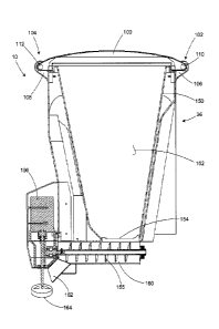
Referring to Figs. 1-3, an exemplary material spreader 10 is shown
mounted to a vehicle 12 for conveying and spreading a spreadable material, for
example, a pickup truck. The truck includes a rearwardly projecting rear
bumper
14, e.g., a bumper that projects rearwardly outwardly beyond the rear gate of
the
pickup truck so that the top surface of the bumper is upwardly exposed. Below
the rear bumper is a rearwardly projecting hitch receiver 16. As is
conventional,
3
CA 3002291 2018-04-20
the hitch receiver can be fixedly attached to the vehicle, for example, by
bolting or
otherwise affixing the hitch receiver to the frame of the vehicle.
With additional reference to Fig. 4, the material spreader 10 includes a
frame 20 having a forwardly projecting hitch mount 22 configured for coupling
to
the rearwardly projecting hitch receiver 16 of the vehicle. The receiver and
the
mount may be coupled in any conventional manner, for example, by inserting the
mount into the receiver and inserting a locking pin through respective bores
24 in
the receiver and the mount. At least one or both of the receiver and mount
preferably include a series of holes to provide horizontally adjustable
mounting of
the frame to the vehicle, which allows the frame to accommodate vehicles
having
different length bumpers. In the illustrated embodiment, and as best shown in
Fig.
4, the mount has a series of horizontally spaced apart holes 25 for this
purpose.
The frame 20 includes a horizontal crossbar 26 connected to the hitch
mount 22, for example, at a top surface of the hitch mount. The connection
between the hitch mount and the crossbar can be reinforced with a gusset 28.
Connected to the crossbar, such as a top surface of the cross bar, is a pair
of
rearwardly extending bars 30. The connection between the crossbar and the
rearwardly extending bars also can be reinforced by gussets 32. The rear end
portions of the rearwardly extending bars are each connected to a pair of
vertical
support members 34 such as brackets.
The brackets 34 support a hopper 36. For example, the brackets can be
coupled to the hopper by a connecting element 28, for example, a bolt, rivet,
screw, etc. Although shown as vertically extending brackets in the exemplary
embodiment of Figs. 1-3, other configurations are possible. For example, the
frame can include a horizontal or angled member for coupling and/or supporting
the hopper.
The brackets 34 provide macroscopic (e.g., large scale) adjustments to the
height of the hopper 36 relative to the frame 20, thereby facilitating the
mounting
of the material spreader 10 onto the vehicle 12. The brackets 34 can include a
plurality bores 38 at different vertical heights for connecting the frame 20
to the
hopper 36 at a variety of different heights relative to the frame. The
brackets
therefore allow the material spreader 10 to be vertically adjusted for
mounting to
vehicles having different vertical distances between the bumper 14 and the
hitch
4
CA 3002291 2018-04-20
receiver 16. For example, in the exemplary embodiment of Fig. 1, the hopper
can
be connected to the brackets by connecting elements 39 though the second set
of
bores from the top of the brackets. Other vehicles may have different bumper
heights and in such vehicles, the frame and the hopper can be connected with a
connecting element through a different set of bores in the brackets so as to
increase/decrease the distance between the hopper and the frame.
The brackets 34 are rearwardly located on the frame relative to a pair of
laterally extending bars 40 configured for connection to respective tie downs
42,
which are located on the front portion of the frame. The laterally extending
arms
are supported by gussets 43. In the illustrated embodiment the bars are spaced
apart from one another, however, other arrangements also are possible. For
example, in an alternative embodiment, the bars can be configured as a unitary
piece (e.g., only a single bar may be utilized and the bars need not be
straight.
The tie downs 42 are connected to the frame 20, for example, at the ends
of the laterally extending bars 40. As shown best in Figs. 2 and 4, the
lateral bars
can include a bore 50 for receiving the tie down 42. The tie down 42 also is
connected to the hopper 36, and as the tie down is drawn down (e.g.,
tightened),
the frame 20 and the hopper are urged towards one another to engage the
material spreader 10 onto the bumper 40. The ends 44 of the lateral bars are
preferably angled to allow access to the tie down, for example, to allow
access to
a nut on the tie down whereby the nut can be tightened to draw the hopper 36
down towards the frame.
The material spreader 10 includes a support 60 having an underside for
resting atop a top surface 61 of the bumper 14. The support 60 may be a
generally planar surface. In a preferred embodiment, the support 60 is formed
by
and is thereby unitary with the hopper 36. For example, the support can be a
bottom surface of the hopper, such as a laterally extending shoulder on the
bottom of the hopper that rests atop the rear bumper. Additionally or
alternatively,
the support can include a portion of the frame, for example, a laterally
extending
generally planar surface for resting on top of the bumper. Although different
configurations are possible, the description herein will primarily refer to
the
support as a bottom surface of the hopper, however, it will be appreciated
that the
principles described herein are equally applicable to other support
configurations.
5
CA 3002291 2018-04-20
The support 60 (e.g., the bottom surface of the hopper) is vertically
movable relative to the frame 20. For example, as described above, large scale
adjustments to the height of the hopper 36 can be effected by connecting the
hopper to different bores 28 in the vertical support members 34 to thereby
raise/lower the hopper. Small scale adjustments (e.g., fine tuning) of the
height of
the hopper relative to the frame can be effected through the tie downs 42
connected to the support and the frame 20, and the tie downs are configured to
urge the support 60 and the hitch mount 22 towards one another to effect a
clamping action on the bumper 14 and the hitch receiver 16.
An enlarged view of an exemplary tie down 42 is shown in Fig. 5. The tie
down 42 is connected to the frame 20 and the hopper 36. The tie down 42 can be
an adjustable member for controlling the clamping action and the force applied
to
the bumper 14 and the hitch receiver 16. In the exemplary embodiment of Fig.
5,
the tie down 42 is a threaded bolt 62 connected to the lateral arm 40 by
inserting
the bolt through the bore 50 in the arm and securing the bolt onto the arm by
a
pair of nuts 64, e.g., locking nuts, on either side of the top wall 46 of the
arm 40.
The opposite end of the bolt is connected to the hopper 36. The tie down may
be
connected to the hopper, for example, by a bracket 66 connected to the hopper.
In the embodiment of Fig. 5, the bracket 66 includes a downwardly facing U-
shape
projection 68, and the bolt is inserted through a hole in the bracket and
through
the hole 50 in the lateral arm. The bolt can be tightened to thereby urge the
hopper towards the frame and effect a clamping action the hitch receiver and
the
bumper. As shown in Fig. 2, the other side of the frame and hopper can be
configured for connection to a second tie down. Although shown as a threaded
bolt arrangement, it will be appreciated the tie downs may be other retention
mechanisms for drawing the hopper towards the frame for effecting a clamping
action, such as, ratchet straps, buckles, clips, belts, etc.
The clamping action between the bumper 14 and the hitch receiver 16
holds the material spreader 10 on the bumper by applying an upward force on
the
hitch receiver with the hitch mount 22 and by applying a downward force on the
bumper 14 with the support 60. The magnitude of the clamping force can be
adjusted by adjusting the tension in the tie downs 42, for example, by
tightening/drawing down the bolt or loosening the bolt 62. The weight of the
6
CA 3002291 2018-04-20
hopper can be supported at least partially by the hitch receiver and the
bumper
when the material spreader is mounted to the vehicle.
As mentioned above, the support 60 of the material spreader 10 rests atop
the bumper 14 and the material spreader is mounted to the bumper with a
clamping force. The material spreader therefore does not require or cause
permanent modifications to the truck to effect a secure attachment thereto.
Additionally, removal of the material spreader can be accomplished by
loosening
the lock member to thereby relieve the clamping force on the bumper by the
hopper, allowing the hopper to be slid off of the bumper after disengaging the
to hitch receiver from the hitch mount on the frame.
Additional features of the material spreader 10 are shown in Fig. 2. The
material spreader may include a vibrator 80 for facilitating the transport of
spreadable material from the hopper 36 to a spinner by vibrating the material
spreader to reduce the likelihood of the material becoming jammed. The
vibrator
can be connected to an electrical supply, for example the battery of the
vehicle, by
a wiring harness 82. The material spreader also may include a shield 84 for
protecting the underside of the truck from the spreadable material as the
material
is distributed from the material spreader. Additionally, the material spreader
may
have a protector 86 for protecting the material spreader from damage, for
example, by shielding the material spreader. The protector extends rearwardly
outward from the frame such that the protector contacts any objects behind the
truck before the material spreader, thereby reducing the likelihood of the
spreader
being damaged, for example, if the truck is accidentally backed up into a snow
bank or another object.
With additional reference to Figs. 6-10, the hopper 36 is shown in more
detail. The hopper can be any suitable container for holding material to be
spread, for example, granular material (e.g., salt or sand) and/or a liquid
material.
In the illustrated embodiment, the hopper is generally rectangular in shape
and
has sloping side walls for funneling material to both an auger and a spinner,
as
described in more detail below. The hopper is connected to and supported by
the
frame 20 as described above. The open top of the hopper can be closed with a
removable lid 100.
7
CA 3002291 2018-04-20
As shown best in Figs. 6 and 7, the lid 100 is a dual hinged removable lid
that is releasable such that the lid can be opened to different open positions
to
allow the hopper to be loaded from different sides. For example, the lid can
be
openable to a first open position (Fig. 6) so that the hopper can be loaded
from
the rear of the vehicle, and a second open position (Fig. 7) so that the
hopper can
be loaded from the truck (e.g., with material stored in the bed of the truck).
The material spreader includes two sets of hinges located on different sides
of the material spreader for opening the lid. As shown in the illustrated
embodiment, one hinge 102 is located on a frontward side of the material
io spreader 10 and a second hinge 104 is located on a rearward side of the
material
spreader, however, the hinges can be located on adjacent sides of the material
spreader (e.g., perpendicular to one another) or on the left and right sides
of the
hopper. Additionally, the hinges can be configured for connection to different
shaped lids, for example, as may be used circular, rectangular, or other
shaped
hoppers. The hinges 102 and 104 include both hopper hinge elements and lid
hinge elements.
The hopper 36 has a first set of laterally spaced apart hopper hinge
elements 106 on one side (e.g., the front side of the hopper) and a second set
of
laterally spaced apart hopper hinge elements 108 on a different side (e.g.,
the rear
side of the hopper). Likewise, the lid has respective sides with corresponding
first
and second sets of laterally spaced apart lid hinge elements 110 and 112
configured for releasable connection to corresponding first and second sets of
hopper hinge elements 106 and 108. The lateral spacing between the hinge
elements is best shown in Figs. 1 and 2 with respect to the rearward hinge.
In the illustrated embodiment, the hopper hinge elements 106 and 108 are
hinge bodies and the lid hinge elements 110 and 112 are hinge pins, however,
it
will be appreciated that other configurations are possible, for example, the
hopper
hinge elements can be configured as hinge pins and the lid hinge elements can
be configured as hinge bodies, or the hopper and lid may include a combination
of
hinge bodies and hinge pins.
When the lid 100 is in a closed position (e.g., as shown in Figs. 1-3) the
frontward hinge 102 and rearward hinge 104 hold the lid 100 closed. For
example, in the closed position, the corresponding first sets of hinge
elements
8
CA 3002291 2018-04-20
(e.g., the front hinge bodies 106 and hinge pins 110) engaged and the
corresponding second sets of hinge elements (e.g., the rear hinge bodies 108
and
rear hinge pins 112) are engaged. The corresponding sets of hinge elements are
configured for releasable connection to one another to allow the lid to pivot
upwardly to an open position. From the closed position the lid can be opened
to
the first open position (Fig. 6) or the second open position (Fig. 7).
As shown in Fig. 6, when the lid 100 is opened to the first open position
(e.g., for loading the material spreader from the rear of the truck), the
first
corresponding set of hinge elements are engaged, and the corresponding second
set of hinge elements are releasable to allow the lid to pivot upwardly about
the
front hinge 102 to the first open position.
As shown in Fig. 7, when the lid 100 is opened to the second open position
(e.g., for loading the material spreader from the bed of the truck), the
second
corresponding set of hinge elements are engaged, and the first corresponding
set
of hinge elements are releasable to allow the lid to pivot upwardly about the
rear
hinge 104 to the second open position.
The corresponding sets of hinge elements can be releasable by laterally
deflecting one of the sets of hinge elements relative to the other. For
example,
the hinge bodies 108 on the hopper can be resiliently laterally deflected to
release
the corresponding hinge pins 112 on the lid. The hinge bodies can be laterally
deflected by applying a lateral force to the hinge body, thereby causing the
hinge
body to deflect laterally to disengage and release the hinge pin, thereby to
allow
the lid to pivot on the other corresponding set of hinge elements.
Each hinge body (e.g., hopper hinge elements 106 and 108 in Figs. 8-10)
include an axially extending through bore 114 for receiving respective hinge
pins
110 and 112. The hinge pins 110 and 112 have corresponding axially extending
protrusions 116, for example, nubs, which are sized for insertion into the
bore of a
corresponding hinge body to thereby engage the hinge pin and hinge body. As
shown in the broken lines in Fig. 10, the hinge body is resiliently laterally
deflectable to a deflected position 118 to release the corresponding hinge pin
112.
For example, the hinge body can be deflected such that the hinge pin can be
vertically lifted relative to the hinge body to move the lid from a closed
position to
an open position.
9
CA 3002291 2018-04-20
The deflection in the hinge bodies 106 and 108 may be facilitated by
forming the hinge bodies with a resiliently flexible material, for example, a
thermoplastic elastomer. Additionally or alternatively, one set of hinge
elements
can be resiliently mounted for deflection, for example, by coupling the hinge
elements to a resilient member such as a spring mount. The hinge pins also may
include spring-loaded axially extending pins that can be pressed laterally
inwardly
to disengage the hinge pin from the hinge body. In a preferred embodiment, the
force required to deflect the hinge elements laterally to release the
corresponding
set of hinge elements is about 10-15 pounds of force.
The hinge pins 110 and 112 may be unitary with the lid, for example, by a
molding process. Likewise, the hinge bodies 106 and 108 may be unitary with
the
hopper and formed by a molding process. Alternatively, the hinge pins and
hinge
bodies can be connected to the lid and hopper, for example, by mounting the
hinge elements to the hopper and lid with brackets or another connecting
mechanism. In the exemplary embodiment of Figs. 6-10, the lid hinge elements
are integrally formed with the lid and the hopper hinge elements are connected
to
the hopper by brackets 120.
The hinge pins 110 and 112 can be inserted into the hinge bodies 106 and
108 by laterally flexing the hinge bodies 106 and 108 apart from one another
and
sliding each hinge pin through the bore in each corresponding hinge body. For
example, the deflected position of the hinge is illustrated by the dashed
lines of
Fig. 10. Due to their resiliency, the hinge bodies flex back to the unflexed
state,
thereby surrounding the hinge pins and retaining the lid. Likewise, the hinge
pins
can be released from the hinge bodies by flexing the hinge bodies laterally
outward, thereby releasing the pin from the bore. Additionally or
alternatively, the
hinge pins may be laterally deflectable to disengage the hinge pins from the
hinge
bodies. In the embodiment of Fig. 10, the hinge body is shown in broken lines
in a
laterally outwardly deflected state (e.g., away from the corresponding hinge
body)
for disengaging the hinge body from a hinge pin inserted into the bore through
an
inner side of the hinge body. It should be appreciated that the hinge body
could
likewise be deflected to an inwardly deflected state (e.g., towards the
corresponding hinge body) for disengaging the hinge body from a hinge pin that
is
inserted into the bore through an outer side of the hinge body.
CA 3002291 2018-04-20
As shown best in Figs. 8-10, the hinge body 108 includes an outer support
wall 130 extending outwardly from an outer portion of the hinge body, and an
inner support wall 132 extending outwardly around the bore 114. The inner and
outer support walls 130 and 132 strengthen the hinge body by increasing the
rigidity of the hinge body in the area 134 in which the support walls are
close to
one another and allow flexion in the area 136 of the hinge body in which the
support walls are further apart from one another.
As shown best in Fig. 8, the outer support wall 130 and the inner support
wall 132 are spaced closer to one another around at least a portion of the
bore
io and further apart from one another where the hinge body is connected to
the
hopper. The hinge body is therefore more flexible near the connection point
than
around the bore. In such an arrangement, the support walls can facilitate
flexion
in the region of the hinge body that can effect the greatest lateral
deflection of the
bore relative to the connection point for facilitating release of the hinge
pin from
the hinge body. The outer support walls also strengthen the hinge body in the
area surrounding the bore where the hinge element may be exposed to forces
from the lid, for example, from rotating the lid opened/closed.
Referring now to Fig. 11, the rear portion of the spreading mechanism is
shown in greater detail. As shown in Fig. 11, the hopper 36 includes outer
walls
150 that surround an interior space 152 of the hopper in which the spreadable
material can be loaded. The material is fed through the bottom 154 of the
hopper
to an auger 156.
The auger 156 can be a helical rotating member for feeding the material
from the hopper 36 through a trough 160 located below the hopper. The material
is transported from the trough to a chute 162 where the material is deposited
onto
a spinner 164. The spinner rotates to distribute the material, for example, by
outwardly scattering or spraying the material.
The auger and the spinner are driven in a synchronous relationship by a
drive assembly 166, which shown in Figs. 11 and Fig. 12. The drive assembly
166 is suitable attached to the frame and/or the hopper 36. As shown in the
illustrated embodiment of Figs. 11 and Fig. 12, the gear box is attached to a
rear
side of the hopper 36.
11
CA 3002291 2018-04-20
The drive assembly 166 includes an electric motor 168 that is coupled by a
wire harness 170 to a power supply, for example, the battery of the truck. The
electric motor supplies power to a motor shaft 172 that is coupled to a drive
shaft
174 in a gear box case 176. The drive shaft 174 is connected at one end by a
coupling 178 to the motor shaft 172. The opposite end 178 of the drive shaft
174
is configured for connection to the spinner 164, whereby the spinner operates
at
the same rotational speed as the motor. The gear box case 176 also includes a
pair of bearings 182 and 184 that surround the drive shaft 174.
The gear box case 176 also includes a gear reduction assembly connected
between the auger and the drive shaft for driving the auger at a slower
rotational
speed that the spinner. The gear reduction assembly includes a small gear 186
on the drive shaft 174 in mesh with a large gear 188 on a second drive shaft
190.
The gear box case also includes bearings 192 and 194, which surround the
second drive shaft 190 to facilitate rotation thereof. The second drive shaft
has an
end 196 configured for connection to the auger 156.
The gear reduction assembly and the direct connection of the drive shaft to
the spinner provides a drive assembly that is free from chains, belts and
pulleys,
which are subject to substantial wear and tear, and which break down over
time,
and which frequently need to be serviced and replaced. In contrast, the drive
assembly drive disclosed herein has relatively few parts requiring service and
therefore is less likely to break down than conventional chain/belt/pulley
arrangements.
Although the invention has been shown and described with respect to a
certain preferred embodiment or embodiments, it is obvious that equivalent
alterations and modifications will occur to others skilled in the art upon the
reading
and understanding of this specification and the annexed drawings. In
particular
regard to the various functions performed by the above described elements
(components, assemblies, devices, compositions, etc.), the terms (including a
reference to a "means") used to describe such elements are intended to
correspond, unless otherwise indicated, to any element which performs the
specified function of the described element (i.e., that is functionally
equivalent),
even though not structurally equivalent to the disclosed structure which
performs
the function in the herein illustrated exemplary embodiment or embodiments of
the
12
CA 3002291 2018-04-20
invention. In addition, while a particular feature of the invention may have
been
described above with respect to only one or more of several illustrated
embodiments, such feature may be combined with one or more other features of
the other embodiments, as may be desired and advantageous for any given or
particular application. Furthermore, directional modifiers (e.g., front, back,
upper,
top, lower, bottom, above, below, left-hand, right-hand, etc.) are used only
for
ease in explanation in connection with the illustrated orientation and do not,
unless otherwise indicated, limit the elements to any specific orientation.
13
CA 3002291 2018-04-20