Note: Descriptions are shown in the official language in which they were submitted.
COVER INCLUDING A MONOLITHIC COATING
FIELD
[001] The present teachings relate to a tonneau system that includes a
monolithic coating
over the tonneau system and more specifically a tonneau system with a
plurality of tonneau
sections that are foldable relative to each other by a hinge and a monolithic
coating that covers
the tonneau sections, the hinges, or both to prevent fluid from penetrating
the tonneau system.
BACKGROUND
[002] Tonneau systems cover an open area of a vehicle and generally cover
an open
area of a pick-up truck (i.e., a bed). Multiple different types of tonneau
systems are available,
however, many of these systems have an exterior where joints, hinges, or
elastomeric hinges
are visible. These joints, hinges, or elastomeric hinges may prevent all of
the panels from
being painted or the tonneau system from having a continuous exterior surface
such that the
tonneau system may not have a clean exterior surface. These systems include a
plurality of
panels that are folded one on top of another and the panels rotate about the
hinges. The
hinges, joints, or elastomeric hinges may require one or more connection areas
where fluids
may penetrate so that the fluids may extend into the truck bed. Items may be
stored in the
truck bed that are intended to stay dry such that an introduction of a fluid
such as water into the
truck bed may potentially damage the items or require the items to be dried
before the items
are used.
[003] Examples of tonneau systems and attempts to create covers that resist
fluid
penetration are found in U.S. Patent Nos. 5,595,417; 5,636,893; 5,795,011;
6,221,290;
6,948,761; 7,157,388; 7,442,441; 7,484,788; 8,960,765; and 9,211,834. It would
be desirable
to have a coating that covers the panel and the frame to create a fluid
barrier over a connection
between the frame and the panel. What is needed is a coating that extends over
the panel and
a hinge in a frame and forms a fluid barrier over the panel and the hinge. It
would be desirable
to have a coating that when applied over a hinge permits movement of the hinge
without the
coating being damaged and prevents fluid penetration when in a stored
position. What is
needed is a coating that bonds to and resists fluid penetration through
multiple types of
material. It would be attractive to have a coating that is sufficiently strong
to protect panels, a
hinge, and a frame from damage, but is sufficiently flexible to move with the
hinge.
1
CA 3002379 2019-10-24
SUMMARY
[004] The present teachings seek to help solve one or more of the
problems/issues
disclosed above. The present teachings are particularly directed to a coating
that extends over
a panel and a frame and/or hinge along a top side of a tonneau system. The
present teachings
are directed to a coating that protects the tonneau cover and prevents fluid
from penetrating
the tonneau system.
[005] Accordingly, pursuant to one aspect of the present teachings
provides: a foldable
tonneau system comprising: (a) a plurality of frames, each of the plurality of
frames include a
panel region and a hinge region; (b) a plurality of panels each connected to
one or more of the
plurality of frames via the panel region; (c) a plurality of hinges that
extend between and into
the hinge region of a first of the plurality of frames and the hinge region of
a second of the
plurality of frames and connect the first of the plurality of frames to the
second of the plurality of
frames so that two of the plurality of panels are movable relative to each
other; and (d) a
coating that covers all or a portion of the plurality of panels, all or
portion of the plurality of
frames, and a connection region where each of the plurality of panels connect
to the one of the
plurality of frames at the panel region so that fluid is prevented from
entering the connection
region.
[006] The present teachings provide: a foldable tonneau system comprising:
a method
comprising: (a) inserting one of a plurality of panels into a panel region of
one of a plurality of
frames; (b) inserting a first end of one of a plurality of hinges into a hinge
region of the one of
the plurality of frames; (c) inserting a second end of the one of the
plurality of hinges into a
hinge region of a second of the plurality of frames; and (d) applying a
coating over the one of
the plurality of panels and all or a portion of the one of the plurality of
hinges and all or a
portion of the second of the plurality of frames.
[007] The present teachings provide: a foldable tonneau system comprising:
(a) a plurality
of frames, each of the plurality of frames include a panel region and a hinge
region; (b) a
plurality of panels each connected to one or more of the plurality of frames
via the panel region;
(c) a plurality of hinges that extend between and into the hinge region of a
first of the plurality of
frames and the hinge region of a second of the plurality of frames and connect
the first of the
plurality of frames to the second of the plurality of frames so that two of
the plurality of panels
are movable relative to each other; and (d) a coating that covers all or a
portion of the plurality
of panels, all or portion of the plurality of frames, all or a portion of the
plurality of hinges, or a
2
CA 3002379 2019-10-24
combination thereof; wherein the coating includes a cross-linked elastomeric
polymer including
urea linkages.
[008] The present teachings provide a coating that covers the panel and the
frame to
create a fluid barrier over a connection between the frame and the panel. The
present
teachings a coating that extends over the panel and a hinge in a frame and
forms a fluid barrier
over the panel and the hinge. The present teachings provide a coating that
extends over the
panel and a hinge in a frame and forms a fluid barrier over the panel and the
hinge. The
present teachings provide a coating that when applied over a hinge permits
movement of the
hinge without the coating being damaged and prevents fluid penetration when in
a stored
position. The present teachings provide a coating that bonds to and resists
fluid penetration
through multiple types of material. The present teachings provide a coating
that is sufficiently
strong to protect panels, a hinge, and a frame from damage, but is
sufficiently flexible to move
with the hinge.
DESCRIPTION OF THE DRAWINGS
[009] Fig. 1 is a side view of a tonneau cover on a vehicle with the
tonneau cover being in
the closed position;
[0010] Fig. 2 is side view of a tonneau cover on a vehicle with the tonneau
cover being in
the stored position;
[0011] Fig. 3 is a perspective view of tonneau cover with a tonneau section
being folded;
[0012] Fig. 4 is a close-up view of a frame with a hinge connecting two
panels with a
coating applied over the frame and panel;
[0013] Fig. 5 is a close-up view of a frame with a hinge connecting two
panels with a
coating applied over the frame, panel, and hinge;
[0014] Fig. 6 is a close-up view of a frame with a hinge connecting two
panels with a
coating applied over the frame, pane, and hinge with a relief in the hinge;
[0015] Fig. 7 is a close-up view of a frame with a hinge connecting two
panels with a
coating applied over the frame, panel, and a portion of the hinge;
[0016] FIG. 8 is a close-up view of a frame with a hinge connecting two
panels with a
coating applied over the frame, panel, and hinge with a recess in the panel;
[0017] FIG. 9 is a close-up view of a frame with a hinge connecting two
panels with a
coating applied over the frame, panel, and hinge with a thinned region in the
hinge; and
[0018] FIG. 10 is an exploded view of a frame and a panel.
3
CA 3002379 2019-10-24
DETAILED DESCRIPTION
[0019] The explanations and illustrations presented herein are intended to
acquaint others
skilled in the art with the teachings, its principles, and its practical
application. Those skilled in
the art may adapt and apply the teachings in its numerous forms, as may be
best suited to the
requirements of a particular use. Accordingly, the specific embodiments of the
present
teachings as set forth are not intended as being exhaustive or limiting of the
teachings.
[0020] The foldable tonneau system (tonneau system) functions to cover an
open area and
prevent fluid, debris, dirt, or a combination thereof form entering the open
area (e.g., a bed or
cargo box of a vehicle such as a pick-up truck, and hereinafter "bed"). The
tonneau system
may cover a bed of any vehicle (e.g., a pickup, El Camino). The tonneau system
may function
to lock a bed so that items may be stored within the bed. For example, when
the tonneau
system is in a closed position the tonneau system may close the bed of a
vehicle and
preferably a bed of a truck. The tonneau system may be collapsible (e.g.,
movable between a
closed position and a stored position) so that items may be placed within the
bed without
interference from the tonneau system. The foldable tonneau system may be
located within a
single plane when the tonneau system is in the closed position. The tonneau
system may be a
plurality of sections that are folded upon themselves to move to a stored
position. The tonneau
system may fold upon itself to expose the bed. The tonneau system may include
one or more
tonneau sections and preferably a plurality of tonneau sections.
[0021] The tonneau sections (i.e., section) function to connect together to
create one
contiguous surface. The tonneau sections may lock together. The tonneau
sections may be
longitudinally movable, rotationally movable, or both relative to other
tonneau sections. The
tonneau sections when in a closed position may prevent fluid, debris, dirt, or
a combination
thereof from entering a bed. The tonneau sections may be separate pieces. The
tonneau
sections may be connected together by a hinge, an outer covering, or both. The
tonneau
sections may be connected together by a cover that is flexible so that one
tonneau section is
movable relative to another tonneau section. The tonneau sections may include
a frame. The
tonneau sections may include one or more frame members. The one or more frame
members
may extend along a length of each section, form a perimeter of the foldable
tonneau system, or
both. The tonneau sections may be free of a frame. The tonneau sections may be
a panel
connected to a frame. A plurality of tonneau sections may be connected
together by one or
more hinges. The panels, frame, or both of each tonneau section may include an
outer
covering. The outer covering may have some elastomeric properties that allow
one tonneau
4
CA 3002379 2019-10-24
section to be longitudinally moved relative to another tonneau section. The
outer covering may
prevent water from penetrating between the tonneau sections in the closed
position, extended
position, stored position, or a combination thereof. The cover may extend over
more than one
tonneau section. The cover may extend from an end of a tonneau section to
another end of a
tonneau section so that a gap between the tonneau sections are covered.
Preferably, the
outer covering only covers the panels of the tonneau sections.
[0022] The one or more panels when laid flat function to cover a bed of a
vehicle. The one
or more panels may extend from a driver side to a passenger side of a bed. The
one or more
panels when in series may form a plane. The one or more panels may be a single
layer.
Preferably, each panel may be a plurality of layers connected together. The
one or more
panels may include a core layer, a covering on a first side, a covering on a
second, side, or a
combination thereof. The one or more panels may include a top skin material
and a bottom
skin material with a high tensile strength and a lightweight core material
that when combined
together create a structure with a high flexural strength. The flexural
strength may be about
2500 MPa or less, about 1500 MPa or less, about 1000 MPa or less, or about 750
MPa or less.
The flexural strength may be about 10 MPa or more, preferably about 20 MPa or
more, more
preferably about 50 MPa or more, even more preferably about 100 MPa, or most
preferably
about 250 MPa or more. For example, an uncoated panel may have a flexural
strength of
about 16 MPa and a coated panel may have a flexural strength of about 30 MPa.
The panels
may be made of a sheet moulding compound. The panels may be made of a polymer,
foam,
metal, aluminum, titanium, polystyrene, expanded polystyrene, acrylonitrile
butadiene styrene
(ABS), or a combination thereof. The panels may be made of an open cell foam,
a closed cell
foam, or a combination of both. Preferably, the panels are made of aluminum
skins with an
expanded polystyrene material core. The one or more panels may include a core
layer, a
covering on a first side (e.g., a skin), a covering on a second, side, or a
combination thereof.
[0023] The one or more panel cores may function to provide structural
rigidity of the panel.
The one or more panel cores may function to extend from a driver side to a
passenger side,
from a front end to a rear end, extend part of a distance between a front end
and a rear end, or
a combination thereof. The panel core may be substantially rigid. For example,
the panel core
may be able to support a weight of about 10 Kg or more, about 25 Kg or more,
about 50 Kg. or
more, or even 100 Kg. or more. The panel core may be able to support a weight
of about 250
Kg. or less or about 200 Kg or less. The panel core may include one or more
reinforcements.
For example, the panel core may include one or more pieces of metal that are
included within a
molded material, a molding compound, a foam, a polymer, or a combination
thereof. The one
CA 3002379 2019-10-24
or more panel cores may be fluid resistant. The one or more panel cores may
resist fluid from
passing through the panel. The panel core may not be fully hydrophobic,
scratch resistant,
dent resistant, or a combination thereof and may include one or more skins to
protect the panel
core, provide fluid resistance, or both.
[0024] The one or more skins may be an outer layer that functions to
protect the panel
core, resist fluid from entering the bed or cargo box, create a dent resistant
layer, create a
scratch resistant layer, or a combination thereof. The one or more skins may
be a hardened
material that may be substantially impermeable to damage when items are placed
upon the
tonneau system. The one or more skins may be rigid. The one or more skins may
have some
elastomeric characteristics and may have some give when contacted by other
items so that the
skin is not damaged. The one or more skins may be made of aluminum; wood; a
fibrous
material (e.g., an engineered paper product, woven material, fiber glass,
carbon fiber, or a
combination thereof); polyethylene; fiber reinforced plastic; acrylonitrile
butadiene styrene
(ABS); thermoplastic olefin (TP0); reinforced polymers; or a combination
thereof. The one or
more skins may be the coating discussed herein or the one or more skins may be
a layer that
is added and then a coating applied over the skin. The one or more skins may
be in roll form,
sheets, or both and then added to the panel core. The one or more skins may be
applied by
gluing, spraying, dipping, rolling, or a combination thereof. The one or more
skins may be on a
first side (e.g., exterior surface relative to the cargo box when the tonneau
system is in the
closed position), a second side (e.g., interior surface relative to the cargo
box when the
tonneau system is in the closed position), a height (e.g., one or more walls
that extend between
the first surface and the second surface), or a combination thereof. The one
or more skins may
assist in sealing a connection region when the panel is placed into a panel
region of a frame.
The one or more skins, the panel core, or both may compress as the panel is
moved into the
frame and then the one or more skins, the panel core, or both may expand to
seal the
connection region to prevent fluid from entering between the frame and the
panel.
[0025] The connection region may function to connect two or more pieces of
the tonneau
system together. The connection region may connect a frame to a panel, a hinge
to a frame,
or both. The connection region may have one part of the tonneau system
inserted into another
part of the tonneau system. The connection region may be any region where two
parts come
together. The connection region may be a region where fluid may enter the
tonneau system.
The connection region may have one or more gaps that may allow fluid to enter
between two or
more parts of the tonneau system. The connection region may be sealed, covered
by a
coating, or both. The connection regions may be internally sealed (e.g., by
expansion of the
6
CA 3002379 2019-10-24
panel core, the skin, a hinge, or a combination hereof) and externally sealed.
The connection
regions may connect two or more discrete parts together to form a tonneau
section or the
tonneau system. The connection regions may include one or more connection
walls, one or
more hinge regions, one or more relief cuts, or a combination thereof.
[0026] The one or more relief cuts may function to countersink the frame
relative to the
panels. The one or more relief cuts may function to create a flush surface
between the frame
and the panel. For example, an exterior surface of the frame and an exterior
surface of the
panel may be in a single plane. The relief cut may be an exterior surface, an
interior surface,
or both of the panel. The relief cut may be an absence of one of the layers of
the panel. The
relief cut may be a thinned region of one layer of the panel. The relief cut
may be a machined
surface formed into the panel, a molded depression, a stamped area, or a
combination thereof.
The relief cuts may have a thickness that is substantially equal to a
thickness of the frame.
The relief cuts may prevent a step between the panel and the frame. An end of
the frame may
be in contact with or located proximate to an end of the frame so that fluid
is prevented from
entering into the connection region between the frame and the panel. An end of
the frame may
compress a wall of the relief cut so that fluid is prevented from entering
between the frame and
the wall of the panel (e.g., a vertical wall). The relief cut may have a
height (or depth) that is
substantially the same as the thickness of the panel. The relief cut may have
a height of about
1 mm or more, about 2 mm or more, about 3 mm or more, about 5 mm or more, or
about 1cm
or more. The relief cut may have a height of about 10 cm or less, about 7 cm
or less, or about
cm or less. The relief cuts may have a length that is substantially equal to a
length of the
frame from the end wall. The relief cut may have a length that is about 0.5 mm
or less, about 1
mm or less, or about 2 mm or less than the frame from the end wall so that an
end of the frame
contacts the wall of the relief cut. Thus, for example, if the length of the
frame is about 5 cm,
the length of the relief cut may be about 4.5 cm or less so that a terminal
end of the frame
contacts a wall of the relief cut to prevent fluid from extending through the
connection region.
The frame when in the relief cut may form an exterior surface, an interior
surface, or both of a
portion of a panel. The one or more relief cuts may include a compression
material and a wall
of a frame so that the relief cut assists in forming a seal around the
connection region.
[0027] The compression material functions to prevent environmental
materials from
entering into the connection regions, between the hinge and the frame, or
both. The
compression material may assist in forming a seal. The compression material
may be
compressed as a panel is being inserted into the frame. The compression
material may
elastically deform so that the panel may be inserted into the frame. The
compression material
7
CA 3002379 2019-10-24
may expand to fill gaps or voids so that the compression material prevents
fluid from entering
between the panel and the frame. The compression material may be made of foam,
an open
sell foam, a closed cell foam, a natural rubber, a synthetic rubber, a single
part reactive
chemical applied in liquid form, a multi part reactive chemical applied in
liquid form,
polyurethane, polyethylene, cross-linked polyurethane, reticulated
polyurethane foam, polyvinyl
chloride (PVC), rubber, glue, or a combination thereof. The compression
material may bond to
or be bonded to the panel, the frame, or both so that the panel and frame are
connected
together via the compression material, an adhesive, or both
[0028] The one or more frames may function to connect one or more panels to
a hinge,
two tonneau sections together, or both. The one or more frames may connect to
a panel on
one side (e.g., a panel region) and a hinge on a second side (e.g., a hinge
region). The one or
frames may receive all or a portion of the hinge, the frame, or both. The one
or more frames
may extend along a first surface, a second surface, or both of the panel, the
hinge, or both.
The frame may have a "U"-shape, a "C"- shape, a "H"-shape, or a combination
thereof. The
frame may be made of metal, plastic, a polymer, an extruded material, a
stamped material, or a
combination thereof. The frame may be made of aluminum, titanium, steel,
stainless steel, or a
combination thereof. The frame may include one or more connectors. Preferably,
the frame
includes two or more connectors that are located back to back.
[0029] The connectors may function to connect the frame to a panel, a
hinge, or both. The
one or more connectors may be separated by an end wall. Each frame preferably
has at least
two connectors. The end wall of the connector may be an end wall of both a
panel region and
a hinge region of the frame. The connectors may connect the frame to the
panel, connect the
frame to the hinge, or both. The connectors may extend into a portion of the
panel, the hinge,
or both. The connector may hold the panel and the frame together. The
connector may
include one or more walls, an end wall, or a combination thereof of that
receive the panel, the
hinge, or both.
[0030] The walls function to retain a panel in place, a hinge in place, or
both. The walls
function to connect to a portion of a panel, a portion of a hinge, or both.
The walls may be
generally parallel to each other. The walls may be substantially rigid. The
walls may have
some flexibility. The walls may diverge towards each other to hold the panel,
the hinge, or
both. The walls may be bonded to the panel, the hinge, or both. The walls may
create a
friction fit with the panel, the hinge, or both. The walls may have an open
end and a closed
end. The walls may terminate at an end wall.
8
CA 3002379 2019-10-24
[0031] The end wall may separate the panel (e.g., panel region) and the
hinge (e.g., hinge
region). The end wall may prevent the panel, the hinge, or both from being
moved in a first
direction. The end wall may be perpendicular to the walls. The end wall may
connect to the
panel, the hinge, or both. The end wall may extend generally parallel to one
or more
connection walls.
[0032] The one or more connection walls function to grip or retain a hinge,
a panel, or both.
The connection walls may be a portion of a wall angled from a first direction
to a second
direction. For example, the one or more connection walls may be curved inward
along a radius
so that the first wall and the second wall extend towards each other. The one
or more
connection walls when curved towards each other may have a space therebetween.
A hinge
may extend through the space between two connection walls and have a portion
located on a
first side of the connection walls and a portion on a second side of the
connection walls. The
connection walls may prevent the hinge from being removed from frame. The
connection walls
may extend inward from the walls. The connection walls may be a terminal part
of the frame.
The connection walls may be in intermediate part of the frame. The connection
walls may be a
discrete wall that extends inward from a wall. Preferably, a connection wall
connected to an
external wall curves inwards and a connection wall connected to an internal
wall is located
inward from a terminal end of the internal wall. The connection walls may be
located between
one or more fingers and the end wall.
[0033] The one or more fingers may function to support the hinge, contact a
support of the
hinge, or both. The one or more fingers may have a cantilevered connection.
The one or more
fingers may extend from an interior wall, an exterior wall, or both.
Preferably, the one or more
fingers may extend from an interior wall of the frame towards the exterior
wall of the frame.
The one or more fingers may curve upward into contact with the hinge or a
support of the hinge
to maintain the hinge in a planar manner, prevent sagging, or both. The one or
more fingers
may extend from a first frame towards a second frame and then upward into
contact with a
hinge and a second of the one or more fingers may extend from a second frame
towards a first
frame and then upward into contact with the hinge. The one or more fingers may
directly
contact the hinge. Preferably, the one or more fingers directly contact a
support of a hinge.
The one or more fingers may extend from the hinge region of the frame. The one
or more
fingers may extend in a direction opposite the panel region.
[0034] The panel region functions to receive a panel and connect the panel
to the frame.
The panel region may extend around an interior surface, an exterior surface,
or both of the
9
CA 3002379 2019-10-24
panel. The panel region may connect to the panel. The panel region may be
adhered to a
panel. The panel region be located on a side of the frame opposite the hinge
region.
[0035] The hinge region may function to connect a portion of the hinge to
the frame. The
hinge region may extend around an interior surface, an exterior surface, or
both of the hinge.
The hinge region may connect to the hinge. The hinge region may create a
friction fit with the
hinge. The hinge region may be adhered to the hinge. The hinge region may
connect a frame
to a first side of a hinge and a second frame to a second side of the hinge.
The hinge region
when connected to a hinge may include a connection region.
[0036] The one or more hinges may function to connect two or more tonneau
sections
together. Preferably, the one or more hinges each connect one tonneau section
to a directly
adjacent tonneau section. The one or more hinges may be hidden from view when
the
tonneau sections are in a closed position. A portion of the one or more hinges
may be visible
in the closed position, the stored position, or both. The one or more hinges
may function to
permit one section to rotate relative to another section. The one or more
hinges may prevent
one section from contacting a second section, a third section, or both when
the sections are in
a stored position. The one or more hinges may permit one tonneau section to
move
longitudinally, rotationally, or both relative to another tonneau section, but
to remain connected
to the tonneau section. The hinge may permit movement in one or more planes.
Preferably,
the hinge permits movement in two or more planes in series or in parallel. The
one or more
hinges may assist in moving a tonneau section from a closed position to an
open position.
Preferably, the one or more hinges may assist in moving a tonneau section from
a stored
position (e.g., an open position) to a closed position. Even more preferably,
the one or more
hinges may assist in moving the one or more tonneau sections from a partially
rotated position
to a closed position. The one or more hinges may prevent the tonneau sections
from moving
laterally (i.e., side to side). The one or more hinges may extend from one
section to another
section and vertically support the sections so that a gap is created between
the sections. The
hinges may be located on a driver side, a passenger side, a middle, one or
more side regions,
one or more central regions, or a combination thereof. Preferably, at least a
first side region
and a second side region include a hinge. The hinge may extend between and be
connected
to two tonneau sections. The hinge may include one or more connector portions.
[0037] The one or more connector portions function to connect an end of the
hinge to the
hinge region of the panel. The one or more connection portions may have a
generally square
cross-section. The one or more connection portions may have a narrow region.
The one or
more connection portions may have portions may have a "T" shaped portion or an
"H" shaped
CA 3002379 2019-10-24
portion. The one or more connection portions may have a portion that is
located within the
hinge region and a portion that is located outside of the hinge region. The
one or more
connector portions may extend into the hinge region so that the hinge is
connected to the
frame. Preferably, the one or more connector portions are located inside the
hinge region.
The one or more connector portions may be located inside of the connection
wall. The one or
more connector portions may be connected to one or more notched portions.
[0038] The one or more notched portions may function to connect the hinge
to the frame.
The one or more notched portions may function to receive one or more
connection walls to
connect the hinge to the frame. The one or more notched portions may prevent
the hinge from
being removed from the frame, the hinge region, or both. The one or more
notched portions
may be an absence of material. The one or more notched portions may create a
friction fit with
the connection wall. The one or more notched portions may receive the
connection wall so that
a connector portion is located on a first side of the connection wall and the
hinge joint is
located on a second side. The one or more notched portions may be located
adjacent to the
supports.
[0039] The one or more supports may function to assist in preventing the
flexible region,
the hinge joint, or both of the hinge from sagging. The one or more supports
may extend from
a lower surface of the flexible region, the hinge joint, or both so that the
hinge joint, the flexible
region, or both are maintained in a planar relationship. The one or more
supports may be
contacted by one or more fingers so that the hinge is supported. The one or
more supports
may be located on a bottom side of the flexible region.
[0040] The one or more flexible regions function to assist the tonneau
system from moving
between a stored position and a closed position. The flexible region may move
so that one or
more panels move from in plane with each other to parallel to each other. The
one or more
flexible regions may rotate by about 90 degrees or more or about 180 degrees
or more and
about 270 degrees or less. When one flexible region is present the flexible
region may rotate
by about 180 degrees. When two flexible regions are present together the
flexible regions may
each rotate by about 90 degrees. The one or more flexible regions may be hinge
joint that the
hinge, the panels, or both rotate about.
[0041] The one or more hinge joints may function to be a pivot point that
the flexible region,
the hinge, the panels, or a combination thereof rotate about. The one or more
hinge points
may be a thinned area where the hinge moves, fold, bend, or a combination
thereof. Each
hinge may have a single hinge joint that the hinge rotates about. Each hinge
may have a
plurality hinge points that the hinge bend about so that the panels may be
rotated from in plane
11
CA 3002379 2019-10-24
to a second plane parallel to the plane. The hinge joints may be formed in
predetermined
locations. The hinge joints may be formed by thinning one or more regions of
the hinge.
[0042] The one or more thinned regions may function to permit movement of
the panels
relative to each other. The one or more thinned regions may permit one tonneau
section to be
stored above a second tonneau section. The one or more thinned regions may be
an absence
of material where a coating is applied so that the hinge and coating may be
moved and/or
folded without damaging the hinge or coating. The one or more thinned regions
may be free of
contact with a coating. The one or more thinned regions may be a reduction in
material in a
specification region relative to the surrounding regions so that a weakened
location is formed.
The one or more thinned regions may expand along an entire height, length,
width, or a
combination thereof of the hinge. The one or more thinned regions may be a
localized region.
The one or more thinned regions may be located in an interior region (e.g.,
bottom of a hinge
(i.e., a side that faces the bed)). The one or more thinned regions may be
located in an
exterior region (e.g., a top of a hinge (i.e., a side that faces away from the
bed)). The one or
more thinned regions may assist the coating is rotating without being damaged.
The hinge
may include one or more thinned regions, one or more hinge relieves, or both.
[0043] The one or more hinge reliefs may function to assist the hinge is
moving, closing,
rotating, or a combination thereof. The one or more hinge reliefs may function
to assist the
coating in folding, rotating, moving out of plane, or a combination thereof.
The one or more
hinge reliefs may be in a localized region. The one or more hinge reliefs may
extend from one
frame to a second frame. The one or more hinge reliefs may be located an
exterior region of
the hinge. The one or more hinge relieves may be an absence of material in an
exterior
surface of a hinge. The hinge relief may be a thinning of material, a removal
of material, or
both. The hinge relief may be a saddle, a U-shape, below a plane, a V-shape,
or a
combination thereof. The hinge relief may extend between supports. The hinge
relief may
extend between ends of coating. The hinge relief may receive additional
material so that the
coating is thicker in the relief. The hinge relief may receive less material
so that the coating in
the relief may be thinned. The hinge relief may assist the hinge, the coating,
or both in bending
so that the coating, hinge, or both are free of cracks, failures, stress
regions, or a combination
thereof. The hinge reliefs may work with the thinned regions so that the hinge
and coating
rotate when the tonneau sections are moved into a stored position.
[0044] One or more coatings may be applied over the one or more panels, the
one or more
frames, the one or more hinges, or a combination thereof. The one or more
coating may be
located in a single plane on an exterior surface of the panels, the frame, the
hinge, or
12
CA 3002379 2019-10-24
combination thereof. The one or more coatings may have ends where the coating
stops at
predetermined locations. Preferably, the coatings extend over the connection
regions between
the panel and the frame, the frame and the hinge, or both. The coating may be
formed of one
or more coating materials for protecting the panels from damage. For example,
the coating
may protect the frame from environmental damage (such as humidity, salt,
light, heat, rain, or
any combination thereof) or damage from impact or abrasion. The coating may
also protect the
frame from damage. For example, the coating may prevent water from contacting
one or more
surfaces of the frame. The coating may also protect the hinge from damage. For
example, the
coating may protect the hinge from a damage discussed above with respect to
the panel and
the frame. Additionally, coating may prevent damage to the hinge that would
prevent the hinge
from functioning (e.g., folding by 90 degrees or more, or by about 180
degrees).
[0045] The coating material should adhere to the panel, either directly or
with the aid of
one or more primers or other adhesion promoters. Preferably the coating
material directly
adheres to the panel. The adhesion between the coating material and the panel
may be
characterized by a cohesive failure of about 50% or more, preferably about 75%
or more, more
preferably about 90% or more, and most preferably about 100%, as measured by
ASTM
D1002-10. In various aspects of the teaching herein, it may also be preferable
for the coating
material to also have good adhesion to the frame and/or the hinge. As such,
the adhesion
between the coating material and the frame or hinge may be characterized by a
cohesive
failure of about 50% or more, preferably about 75% or more, more preferably
about 90% or
more, and most preferably about 100%, as measured by ASTM D1002-10.
[0046] The coating material preferably includes, or consists of one or more
polymers that
adhere to the surface of the panel, frame, or hinge (e.g., directly to the
panel, frame, or hinge,
or to a primer or other adhesion promoter applied to the component). The
polymer of the
coating material may be formed of monomers or prepolymers that adhere to the
surface(s), or
may have a functional group that enhances the adhesion. The functional group
preferably is a
pendant functional group attached to the backbone of the polymer or is an end
functional group
attached to a chain end.
[0047] The coating material should be sufficiently flexible so that it can
cover (without
adhesion) or coat (with adhesion) and allow the hinge to repeatedly flex from
an open to closed
position. For example, the coating material should not tear or otherwise fail
after repeated
opening and closing of the hinge for about 100 cycles, for about 500 cycles,
for about 1000,
cycles, or for about 2000 cycles. If the coating material is too stiff, it may
have a brittle failure
or may plastically deform during the opening and closing of the hinge.
Preferably the coating
13
CA 3002379 2019-10-24
material is selected so that it has a durometer of about 55 Shore D or less,
about 50 Shore D
or less, about 45 Shore A or less, about 80 Shore A or less, or about 75 Shore
A or less, as
measured according to ISO 868, at 23 C, at 15 seconds of contact. If the
coating material is
too flexible it may fail by tearing. Preferably the coating material is
selected so that it has a
durometer of about 40 Shore A or more, about 50 Shore A or more, or about 60
Shore A or
more. The coating material should be selected to have a generally high
elongation at failure so
that it able to withstand the required stretching in the hinge region.
Preferably, the coating
material has an elongation at failure of about 80% or more, about 100% or
more, about 120%
or more, and more preferably about 150% or more, as measured according to ASTM
D412 at
23 C. The coating material typically has an elongation at failure of about
500% or less,
however higher elongation at failure is also possible. The coating material
may be sufficiently
flexible so that when the coating material is applied to a panel, a hinge, a
frame, or a
combination thereof the coating may be folded by about 90 degrees or more,
about 135
degrees or more, or even about 180 degrees or more without cracking. The
coating material
when applied to a panel, a hinge, a frame, or a combination thereof may be
folded by about
270 degrees or less or about 200 degrees or less without cracking.
[0048] The coating material preferably is sufficiently stiff so that it
provides good protection
against impact and abrasion. For example, the coating material may be
characterized by a
tensile stress at 100% elongation of about 0.5 MPa or more, about 2 MPa or
more, about 4
MPa or more, or about 6 MPa or more, as measured according to ASTM D412 at 23
C. The
coating material preferably has a stiffness that is sufficiently low so that
the resistance to the
opening and closing of the hinge does not cause difficulty in operating the
hinge. For example,
the coating material may be characterized by a tensile stress at 100%
elongation of about 30
MPa or less, about 18 MPa or less, about 12 MPa or less, or about 10 MPa or
less.
[0049] The coating material preferably is substantially or entirely free of
high melt
temperature polymers having a generally high melting temperature (e.g.,
greater than about 90
C, greater than about 110 C, greater than about 130 C, or greater than about
150 C). If
present, the amount of the high melt temperature polymer preferably is about
35 weight
percent or less, about 25 weight percent or less, about 15 weight percent or
less, about 5
weight percent or less, or about 0 weight percent, based on the total weight
of the one or more
polymers in the coating material. The melting temperature may be measured by
differential
scanning calorimetry at a heating rate of about 10 C/min.
[0050] The coating material preferably is substantially or entirely free of
high glass
temperature polymers having a generally high glass transition temperature
(e.g., greater than
14
CA 3002379 2019-10-24
about 50 C, greater than about 70 C, greater than about 110 C, or greater
than about 130
C). If present, the amount of the high glass transition temperature polymer
preferably is about
35 weight percent or less, about 25 weight percent or less, about 15 weight
percent or less,
about 5 weight percent or less, or about 0 weight percent, based on the total
weight of the one
or more polymers in the coating material. The glass transition temperature may
be measured
using dynamic mechanical testing at a heating rate of about 10 C/min and an
amplitude of
about 5%.
[0051] The polymer of the coating material may include a thermoplastic
polymer or a cross-
linked polymer. As used herein, a cross-linked polymer is a polymer having a
sufficient amount
of cross-links so that it does not flow, even when heated to at least 50 C
above its glass
transition temperature and melting temperature. The cross-linked polymer may
be present in
the coating material in an amount of about 30% or more, about 50 weight
percent or more,
about 70 weight percent or more, about 90 weight percent or more, or about 100
weight
percent, based on the total weight of the one or more polymers.
[0052] The coating material may include additional components in addition
to the one or
more polymers. The coating material may include one or more catalysts or cross-
linking
agents. The coating material may include one or more fillers. The one or more
fillers may
include reinforcing filler(s) and/or non-reinforcing filler(s). The coating
material may include one
or more stabilizers, such as a light stabilizer, a heat stabilizer, a
stabilizer to reduce damage
from exposure to salt, ozone, or exhaust gases, or a process stabilizer. The
coating material
may include one or more colorants (e.g., black or other color). The coating
material may
include one or more inhibitors that inhibits the cross-linking of the coating
material until after it
is applied to a surface. The coating material may include one or more flow
modifiers to adjust
the viscosity of the coating material before cross-linking. For example, the
flow modifier may be
an organic or inorganic material that increases or decreases the viscosity of
the coating
material (or a portion of the coating material) before cross-linking. The
amount of the one or
more polymers in the coating material preferably is about 25 weight percent or
more, more
preferably about 40 weight percent or more, and most preferably about 60
weight percent or
more, based on the total weight of the coating material. The amount of the one
or more
polymers may be about 100 weight percent or less, or about 95 weight percent
or less, based
on the total weight of the coating material.
[0053] The coating material preferably is formed by a coating material
composition that
cross-links at a sufficient speed so that it has a gel time of about 30
minutes or less at about 23
C. Preferably the gel time is about 20 minutes or less, more preferably about
10 minutes or
CA 3002379 2019-10-24
less, even more preferably about 5 minutes or less and most preferably about 3
minutes or
less. The gel time may be about 10 seconds or more, about 20 seconds or more,
about 30
seconds or more, or about 45 seconds or more.
[0054] The coating material composition may be provided as a single part
that forms the
cross-linked coating material or as two or more parts that when combined forms
the cross-
linked coating material. For example, the coating material composition may
include or consist
of an A part and a B part which react to form the cross-linked coating
material. The A part and
the B part preferably have similar viscosities so that they can be easily
mixed. For example, the
ratio of the higher viscosity part to the lower viscosity part may be about 50
or less, about 10 or
less, about 5 or less, about 4 or less, about 3 or less, about 2 or less, or
about 1. The A part
and/or the B part may include one or more flow modifiers (such as discussed
herein) and/or
include polymers, monomers or prepolymers selected to achieve the desired
viscosity ratio. For
example, the viscosity of a component may be adjusted by adjusting the
molecular weight of a
polymer or prepolymer in the part. The A part may include a first compound and
the B part
may include a second compound that react to form the cross-links. The first
compound and/or
the second compound is a polymer, a prepolymer, or a monomer. Preferably, the
first
compound and the second compound are each a polymer, a prepolymer, or a
monomer. The
multi-part composition preferably is shelf sable (e.g., at a temperature of
about 30 C) for about
1 month or more, about 3 months or more, about 6 months or more, or about 12
months or
more. One or a multi-functional compound having a functionality greater than
2, for forming the
cross-links. The first compound and/or the second compound may be the multi-
functional
compound, or the multi-functional compound may be present as an additional
compound in the
A part, the B part, or an additional part.
[0055] A particularly preferred coating material composition includes one
or more
monomers, prepolymers, or polymers having at least two isocyanate groups, at
least two amine
groups, at least two imide groups, at least alcohol containing groups, or at
least two alkoxy
groups available for reacting. The coating material composition preferably
includes different
monomers, prepolymers, or polymer having functional groups that react to form
the cross-
linked coating material. For example, the first compound or the second
compound may be a
compound containing at least two isocyanate groups and the other compound may
be a
compound having at least two functional groups capable of reacting with the
isocyanate
groups. The coating material may include a polymer having urea linkages (e.g.,
a polyurea).
The polyurea may be formed from the cross-linking reaction of an isocyanate
(e.g.,
polyisocyanate compound) and an amine (e.g., a polyamine compound). The
coating material
16
CA 3002379 2019-10-24
may include a polymer having carbamate linkages (e.g., a polyurethane). The
polyurethane
may be formed from the cross-linking reaction of an isocyanate (e.g., a
polyisocyanate
compound) and an alcohol (e.g., a polyol). The coating may be a single layer
(e.g., a
monolithic coating) that is applied over the entire exterior surface of the
foldable tonneau
system. The coating may be a plurality of discrete layers that are applied
over predetermined
regions so that there are ends where the coating stops and then begins again
with gaps there
between.
[0056] The ends function to provide flexibility to the coating in high
stress regions. The
ends function to stop once a connection region is covered. The ends may stop
before a
thinned region, a hinge relief, the hinge, or a combination thereof. The ends
may stop on the
frame. The ends may stop before the hinge. The ends may stop on the hinge. The
ends may
be separated by one or more gaps.
[0057] The one or more gaps may be a region between two or more ends of a
coating.
The one or more gaps may be a high stress region that is free of a coating.
The gap may be a
region of a hinge that rotates. The gaps may be located above a hinge region.
[0058] The one or more hinge regions may function to bend, fold, rotate, or
a combination
thereof. The one or more hinge regions may be movable. The one or more hinge
regions may
fold about 90 degrees or more, about 180 degrees or more, or about 270 degrees
or less. The
one or more hinge regions may support one tonneau section over another tonneau
section.
The one or more hinge regions may be free of a coating. The one or more hinge
regions may
be partially coated by a coating. The one or more hinge regions may include
the thinned
region, the hinge relief, or both. The one or more hinge regions may be a
coating that is
folded, bent, or both. The one or more hinge region coatings may be
prestressed upon being
applied to the hinge so that the coating is movable about the pre-stressed
regions. The hinge
regions of the coating may be area between the frames. The hinge regions of
the coating may
following the contours of the hinge, thus, if the hinge has a hinge relief
then the coating may
have a relief.
[0059] The relief functions to assist the coating is moving, bending,
folding, or a
combination thereof without failing. The relief may have a thickness that is
less than the
thickness surrounding the relief (e.g., outside of the hinge regions). The
relief may have a
same thickness as the thickness in the surrounding regions. The relief may
have a pre-bend
so that the coating in the relief folds less than if the relief was not
present. The relief of the
coating may mirror the shape or be complementary to the shape of the hinge
relief.
17
CA 3002379 2019-10-24
L0060] The coating may be applied to the panel, frame, hinge, or a
combination thereof by
one or more method discussed herein. The coating may be applied by spraying
the coating
over the panels, the frame, the hinge, or a combination thereof. The coating
may be sprayed
on like a spray on bed liner or may be a spray on bed liner material. The
coating may be
sprayed on over the panels individually. The coating may be sprayed on the
panels and frame
when the panels and frame are connected together. The coating may be sprayed
on the
panels, frame, and hinge when they are all connected together. The coating may
have a
viscosity so that some of the coating may enter into the connection region of
the tonneau
system. Once applied the coating may permanently bond to the frame, hinge,
panel, or a
combination thereof. The method may include a step of curing the coating with
moisture, heat,
ultraviolet, time, or a combination thereof. The method may include a step of
moving the panel,
the hinge, the frame or a combination thereof to introduce the coating into
the connection
regions. An air knife, roller, blade, or a combination thereof may meter the
amount of coating
applied, smooth the coating, or both.
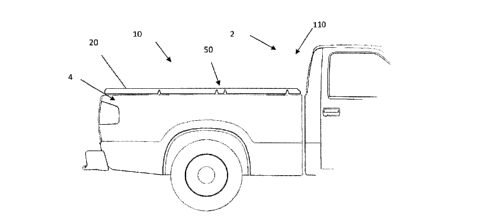
[0061] Figure1 is a side view of a vehicle 2 having a cargo box 4 with a
foldable tonneau
system 10 in a closed position 110 so that the cargo box 4 is covered. The
foldable tonneau
system 10 includes a plurality of tonneau sections 12 with each tonneau
section 12 including a
panel 10 that are connectable together and movable via hinges 50.
[0062] Figure 2 is as side view of the foldable tonneau system 10 in a
stored position 100
so that the cargo box 4 of the vehicle 2 is exposed. The plurality of panels
20 are folded upon
themselves via the hinges 50.
[0063] Figure 3 is a perspective view of a foldable tonneau system 10 being
partially folded
about a hinge 50. The foldable tonneau system 10, as shown, includes panels 20
and hinges
50 that covered by a coating 70.
[0064] Figure 4 is a side view of two tonneau sections 12 connected via a
hinge 50. Each
tonneau section 12 includes a panel 20. The panel 20 includes a panel core 22
that is covered
on both a first side and a second side by a skin 24. The panel 20 extends into
a panel region
42 of the frame 30, which doubles as a connector 32. The frame 30 includes
walls 34 that
extend along both the first side and the second side of the panel 20 when the
panel 20 is
inserted into the frame 30. The panel 20 is inserted into the frame 30 until
the panel 20
contacts an end wall 36. The frame 20 has a hinge region 44 that connects to
the hinge 50.
The hinge region 44 includes a pair of opposing connection walls 38 that
extend towards each
other to extend into a notched portion 54 in the connector portion 52 of the
hinge 50. The
frame 30 also includes a pair of fingers 40 that extends towards and into
contact with the
18
CA 3002379 2019-10-24
supports 56 of the flexible region 58 of the hinge 50 so that the hinge 50
remains planar in the
closed position. A coating 70 extends over the panel 20 and the frame 30. The
coating 70 has
ends 72 that stop before the coating reaches the flexible region 58 so that
the coating is not
flexed with the hinge 50 and a gap 66 is formed between the ends 72. The
coating 70 extends
over a connection region 14 where the panel 20 is joined to the frame 30 and
then has an end
72 that stops before reaching the hinge 50.
[0065] Figure 5 illustrates two panels 20 being connected to a hinge 50 via
two frames 30.
A coating 70 covers the two panels 20, the hinge 50, and the frames 30. The
coating 70 has a
hinge region 74 that flexes with the hinge 50. The coating 70 extends over the
connection
region 14 where the panel 20 connects to the frame 30 and where the frame 30
connects with
the hinge 50.
[0066] Figure 6 illustrates two panels 20 being connected to a hinge 50 via
two frames 30.
A coating 70 covers the two panels 20, the hinge 50, and the frames 30. The
hinge 50
includes a hinge relief 64 that the coating 70 extends into forming a relief
76 in the hinge region
74 that flexes with the hinge 50. The hinge 50 has a thickness (TR) and the
relief 76 of the
hinge 50 has a thickness (TR) which is less than the thickness of the hinge
50. The coating 70
extends over the connection region 14 where the panel 20 connects to the frame
30 and where
the frame 30 connects with the hinge 50.
[0067] Figure 7 illustrates two panels 20 being connected to a hinge 50 via
two frames 30.
A coating 70 covers the two panels 20, the hinge 50, and the frames 30, but
the coating 70
includes ends 72 that do not connect so that the hinge 50 is movable without
all of the coating
being moved. The coating 70 extends over the connection region 14 where the
panel 20
connects to the frame 30 and where the frame 30 connects with the hinge 50 and
then the
coating has two ends 72 that stop on the hinge 50 before connecting.
[0068] Figure 8 illustrates two panels 20 being connected to a hinge 50 via
two frames 30.
The panel 20 include a relief cut 26 that receives a portion a wall 34 of the
frame 30 so that the
hinge 50, frame 30, and panel 20 all form a single plane. A coating 70 covers
the two panels
20, the hinge 50, and the frames 30 and the coating 70 extends in a single
plane. The coating
70 has a hinge region 74 that flexes with the hinge 50. The coating 70 extends
over the
connection region 14 where the panel 20 connects to the frame 30 and where the
frame 30
connects with the hinge 50.
[0069] Figure 9 illustrates two panels 20 being connected to a hinge 50 via
two frames 30.
A coating 70 covers the two panels 20, the hinge 50, and the frames 30. The
coating 70 has a
hinge region 74 that flexes with the hinge 50. The hinge 50 includes a hinge
joint 60 having a
19
CA 3002379 2019-10-24
thickness (HH), the hinge joint 60 has a thinned region 62 having a thickness
(FIT) with the
thinned region 62 that assists the coating 70 and the hinge 50 is moving as
the panels 20 are
moved to a stored position. The coating 70 extends over the connection region
14 where the
panel 20 connects to the frame 30 and where the frame 30 connects with the
hinge 50.
[0070] Figure 10 illustrates an exploded view of a panel 20 being inserted
into a panel
region 42 of a frame 30. The frame 30 includes a hinge region 44 and a panel
region 42. The
panel 20 includes a compression material 28 that extends around the panel 20
so that when
the panel 20 is inserted into the panel region 42 the compression material 28
assists in forming
a seal between the panel 20 and the frame 30. Once connected the panel 20 and
the frame 30
are covered by a coating (not shown).
[0071] Any numerical values recited herein include all values from the
lower value to the
upper value in increments of one unit provided that there is a separation of
at least 2 units
between any lower value and any higher value. As an example, if it is stated
that the amount of
a component or a value of a process variable such as, for example,
temperature, pressure,
time and the like is, for example, from 1 to 90, preferably from 20 to 80,
more preferably from
30 to 70, it is intended that values such as 15 to 85, 22 to 68, 43 to 51, 30
to 32 etc. are
expressly enumerated in this specification. For values which are less than
one, one unit is
considered to be 0.0001, 0.001, 0.01 or 0.1 as appropriate. These are only
examples of what is
specifically intended and all possible combinations of numerical values
between the lowest
value and the highest value enumerated are to be considered to be expressly
stated in this
application in a similar manner.
[0072] Unless otherwise stated, all ranges include both endpoints and all
numbers
between the endpoints. The use of "about" or "approximately" in connection
with a range
applies to both ends of the range. Thus, "about 20 to 30" is intended to cover
"about 20 to
about 30", inclusive of at least the specified endpoints.
[0073] The term "consisting essentially of" to describe a combination shall
include the
elements, ingredients, components or steps identified, and such other elements
ingredients,
components or steps that do not materially affect the basic and novel
characteristics of the
combination. The use of the terms "comprising" or "including" to describe
combinations of
elements, ingredients, components or steps herein also contemplates
embodiments that
consist essentially of the elements, ingredients, components or steps. By use
of the term "may"
herein, it is intended that any described attributes that "may" be included
are optional.
[0074] Plural elements, ingredients, components or steps can be provided by
a single
integrated element, ingredient, component or step. Alternatively, a single
integrated element,
CA 3002379 2019-10-24
ingredient, component or step might be divided into separate plural elements,
ingredients,
components or steps. The disclosure of "a" or "one" to describe an element,
ingredient,
component or step is not intended to foreclose additional elements,
ingredients, components or
steps.
[0075] It is understood that the above description is intended to be
illustrative and not
restrictive. Many embodiments as well as many applications besides the
examples provided
will be apparent to those of skill in the art upon reading the above
description.
[0076] 2 Vehicle
[0077] 4 Cargo box
[0078] 10 Foldable Tonneau System
[0079] 12 Tonneau Section
[0080] 14 Connection region
[0081] 20 Panel
[0082] 22 Panel core
[0083] 24 Skin
[0084] 26 Relief cut
[0085] 28 Compression material
[0086] 30 Frame
[0087] 32 Connector
[0088] 34 Wall
[0089] 36 End wall
[0090] 38 Connection wall
[0091] 40 Finger
[0092] 42 Panel region
[0093] 44 Hinge region
[0094] 50 Hinge
[0095] 52 Connector portion
[0096] 54 Notched portion
[0097] 56 Support
[0098] 58 Flexible region
[0099] 60 Hinge joint
[00100] 62 Thinned region
[00101] 64 Hinge relief
[00102] 66 Gap
21
CA 3002379 2019-10-24
[00103] 70 Coating
[00104] 72 End
[00105] 74 Hinge region
[00106] 76 relief
[00107] 100 Stored position
[00108] 110 Closed position
22
CA 3002379 2019-10-24