Note: Descriptions are shown in the official language in which they were submitted.
Specification
Coil, and magnetic stimulation device using the coil.
Technical Field
[0001]
The present invention relates to a coil, and to a magnetic
stimulation device that uses this coil.
Background Art
[0002]
Transcranial Magnetic Stimulation (TMS) is a method of causing
current flow within the brain by electromagnetic induction, and
stimulating neurons. According to this method, as shown in Fig. 1
to Fig. 3, by applying an alternating current or a given current
waveform to a stimulation coil that has been placed above a person's
scalp, a variable magnetic field is generated, and the effect of
that variable magnetic field is to induce, within the brain, eddy
current in a reverse direction to coil current, and nerve impulses
is generated as a result of stimulation of neurons by this eddy
current. This type of Transcranial Magnetic Stimulation is being
used in clinical laboratory tests and cerebral function research,
including measurement of nerve conduction velocity.
[0003]
In recent years, magnetic stimulation has been gathering
attention as a therapeutic application for neuropathic pain,
Parkinson's disease, depression, etc. With these types of illness,
there are cases where results are not witnessed with treatment using
medicines. For example, for intractable neuropathic pain there is a
method of treatment where electrical stimulation is given to the
brain by implanting electrodes in the brain. However, this method
1
CA 3002978 2019-05-27
of treatment requires a craniotomy, and so many patients are
unwilling to have it performed.
[0004]
Repetitive transcranial magnetic stimulation, where
noninvasive magnetic stimulation, that does not require surgery, is
repeatedly carried out, is therefore being researched as a method
of treatment. With medical treatment for intractable neuropathic
pain, it is being reported that pain relief effects have been
attained at about one day after having carried out magnetic
stimulation on the cerebral primary motor cortex.
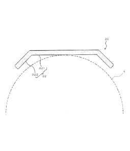
[0005]
However, a conventional magnetic stimulation device has a
weight of about 70 kg, and at the time of installation electrical
work is necessary in order to be able to supply electrical power
from a 200 V power supply, which means that the device can only be
used in well equipped medical facilities. Also,
at the time of
actual treatment, since it is necessary to determine stimulation
position while referencing patient MRI data in accordance with the
disorder to be treated, medical treatment by a medical worker who
is experienced with that situation is necessary. With the treatment
of intractable neuropathic pain, it is necessary to carry out
positioning of a coil on the primary motor cortex, which constitutes
the target, in units of 1 mm.
[0006]
With transcranial magnetic stimulation therapy, as a
stimulation coil for magnetic stimulation, currently various forms
have been proposed, including a circular coil and a figure 8 coil
(a coil that is wound more or less in the shape of the number "8"),
2
CA 3002978 2019-05-27
and further a quatrefoil coil, a Hesed coil, and a coil having
multiple small circular coils arranged on the surface of a head
section, and currently the circular coil and figure 8 coil are mainly
being utilized.
[0007]
A figure 8 coil (refer to patent publication 1 and patent
publication 2 below) has two circular coils, formed in series using
a single conductor, arranged partially overlapping, and by having
electrical current flow in opposite directions in these circular
coils it is possible to cause eddy currents to converge directly
beneath a section where the coils cross, and stimulate a local region.
[0008]
On the other hand, depending on the object of treatment or on
the personal symptoms of the patient, there may be cases where
instead of localized stimulation, stimulation over a wider range is
effective.
[0009]
Also, with a coil that focuses stimulation locally there is a
need to accurately determine position on the target region, and in
this case it is necessary to implement accurate positioning using a
navigation system or the like.
[0010]
As well as carrying out development of magnetic stimulation
used in home treatment, there has also been advancement in
development of navigation systems for determining stimulation
position by a non-medical worker. According to the system, first a
patient is fitted at the hospital with glasses having a magnetic
sensor, and calibration is carried out using a permanent magnet in
3
CA 3002978 2019-05-27
order to attach the glasses at the same position every time. Next,
a doctor specifies optimum stimulation position using a procedure
that combines a patient MRI image and an optical tracking coordinate
system, and the optimum stimulation position, and data for random
positions in a range of 5 cm around the optimum stimulation position,
are stored. By storing surrounding position data, it is possible
to for the patient to visually know where a coil currently is when
determining coil position.
[0011]
At the time of home treatment, first calibration of the glasses
is carried out. After that, three-dimensional position is measured
by comparing position of permanent magnets that are fitted to the
stimulation coil with data. By visually confirming current position
of the coil and optimum stimulation position, it is possible to
Instinctively carry out positioning of the coil.
[0012]
By experimentation it is found that navigation error of this
navigation system is a maximum of, for example, 5 mm from the optimum
stimulation position, while on the other hand if the figure 8 coil
that was described previously has an irradiation position (optimum
stimulation position) within this 5 mm, it is possible to provide
therapeutically effective stimulation of the target region. This
means that at a stimulation position that has been guided by using
a navigation system, if a treatment device that carries out magnetic
stimulation with a figure-8 coil is used, there is a possibility
that a region that is to be radiated (optimum stimulation position)
will not be within the effective stimulation range of the treatment
coil, and so it will he difficult to accurately carry out stimulation
4
CA 3002978 2019-05-27
to the treatment region. Accordingly, it is necessary to develop a
coil that is capable of generating eddy current uniformly over a
wider range, such that in a case where there is a region to be
radiated within, for example, 10 mm, a target region can be
stimulated in a therapeutically effective manner.
[0013]
Therefore, in order to implement a stimulation coil having
high robustness (specifically, being capable of generating uniform
eddy current over a wider range), a dome type coil device (in the
specification below, referred to as "dome type coil") has been
proposed by the present inventors (refer to patent publication 3
below). This dome type coil can cause eddy current to be generated
over a wide range compared to the figure 8 coil, and there is also
the desirable property of being able to reduce inductance while
maintaining inducement of eddy current over a wide range.
[0014]
However, while the dome type coil shown in patent publication
3 below can generate an induced electrical field over a wide range
compared to the figure-8 coil, as already stated, there is a problem
in that electrical field intensity is low in a case where the same
electrical current as with the figure-8 coil has been applied
(approximately 1/4 under the same current application conditions).
[0015]
In a case where induced electrical field is small, more
electrical current must be applied in order to compensate for this,
which means that not only is there a possibility of device cost and
installation cost being increased due to boost circuits and
capacitors being increased in size, there was also a problem in that
CA 3002978 2019-05-27
that coil itself heats up rapidly and it is necessary to take
measures to deal with this.
[0016]
Accordingly, the present inventors have carried out various
experiments regarding coil shape and design parameters, and as a
result have acquired knowledge regarding shapes that have the
advantage of being able to provide the same wide induced electrical
field as a dome type coil while being able to generate a stronger
induced electrical field with approximately the same applied current,
and that can comprises a coil that does not obtain a value of
inductance that has deviated.
Prior Art Publications
Patent Publications
[0017]
Patent Publication 1: Japanese patent laid-open No. 2012-
125546
Patent publication 2: International Patent publication No.
2010/147064
Patent publication 3: International Patent publication No.
2015/122506 (for example, Fig. 6)
Summary of the Invention
6
CA 3002978 2019-05-27
[0018]
The present invention has been conceived based on the
previously described knowledge. An aspect of the present invention
is to provide a coil that can give the same wide induced electrical
field as a dome type coil, and that can generate a strong induced
electrical field with the same applied current as for a dome type
coil, and that can further keep inductance to a small value.
Solution to the Problem
[0019]
Means for solving the above described problem can be described
as in the following aspects.
[0020]
(Aspect 1)
A coil is arranged close to a surface of an object, for causing
an induced electrical field to be generated inside the object,
wherein
the coil has 1st to Nth turns,
the 1st to the Nth turns are respectively provided with an
actuation part for flow of electrical current in one direction and
a connection part for flow of electrical current in a direction
opposite to the one direction,
the actuation parts of the 1st to Nth turns are arranged
parallel to each other, and along a surface of the object or along
a surface that is close to the surface of the object,
the connection parts are arranged within a space in which the
connection parts do not face the surface of the object over
7
CA 3002978 2019-05-27
the actuation parts of the 1st to Nth turns, and the connection
parts are positioned at the sides with respect to the extending
direction of the actuation parts, and
N is an integer of 2 or greater.
[0021]
(Aspect 2)
The connection parts of 1st to Pth turns, within the 1st to
Nth turns, can be arranged over the actuation parts at positions on
the opposite side to the connection parts of 2+1th to Nth turns.
[0022]
(Aspect 3)
The connection parts can be formed in a substantially arcuate
shape.
[0023]
(Aspect 4)
The surface on which the actuation parts can be arranged is
formed having a substantially arcuate cross section.
[0024]
(Aspect 5)
The actuation parts of the 1st to Nth turns can be arranged
at equal intervals.
[0025]
(Aspect 6)
The object can be a living body.
[0026]
(Aspect 7)
The object can be the head of an animal, and
the coil can be configured to produce induced current within
8
CA 3002978 2019-05-27
the brain of the head as a result of the induced electrical field.
[0027]
(Aspect 8)
The coil can be further provided with a core member, and
wherein
the core member is configured to reduce magnetic resistance
of a magnetic circuit that is generated by the 1st to Nth turns, and
the core member is arranged at opposite side to the object,
over the actuation parts.
[0028]
(Aspect 9)
The core member may have a plurality of regions of differing
relative permeability.
[0029]
(Aspect 10)
The core member can be provided with first parts that are
arranged at positions that face the actuation parts, and second
parts that are arranged at positions facing the connection parts,
wherein
the first parts are provided with a plurality of elongated
first core bodies that extend in a direction that is not parallel
to the extension direction of the actuation parts, and
the second parts are provided with a plurality of elongated
second core bodies that extend in a direction that is substantially
parallel to the extension direction of the actuation parts.
[0030]
(Aspect 11)
A magnetic stimulation device can comprise the coil of any one
9
CA 3002978 2019-05-27
of aspect 1 to aspect 10, and a power supply section for supplying
a given electrical current to the coil.
[0031]
(Aspect 12)
A coil can be arranged close to a surface of an object, for
causing an induced electrical field to be generated inside the object,
wherein
a series of conductors of the coil, running from an input
terminal to an output terminal, are made up of
(1) a plurality of actuation conductors used in the induced
electrical field generations, and
(2) connection conductors that connect the plurality of actuation
conductors together, and that are configured in a form whereby effect
on intensity of an induced electrical field that has been generated
by the actuation conductors can be substantially ignored.
[0032]
(Aspect 13)
A magnetic stimulation device can comprise a coil, arranged
close to a surface of an object, for causing an induced electrical
field to be generated inside the object, and a support, wherein
the coil has 1st to Nth turns,
the 1st to Nth turns are respectively provided with an
actuation part for flow of electrical current in one direction and
a connection part for flow of electrical current in a direction
opposite to the one direction,
the actuation parts of the 1st to Nth turns are arranged
substantially parallel to each other,
the connection parts are arranged within spaces, laterally
CA 3002978 2019-05-27
with respect to the extension direction of the actuation parts,
the actuation parts are supported by the support,
a lower surface of the support is formed in a substantially
flat shape, and
N is an integer of 2 or greater.
[0033]
(Aspect 14)
The surface of the object can be a substantially spherical
shape, and a lower surface of the support is therefore configured
to contact a surface of the object substantially at the center of
the support.
Advantageous Effect
[0034]
According to the present invention it is possible to provide
a coil with which efficiency of generating an induced electrical
field with respect to applied current is high even if design. of area
of an actuation part is widened so as to obtain a comparatively wide
induced electrical field, and that can also keep inductance to a low
value.
[0035]
Also, according to the present invention, since change rate
of magnetic flux density at a stimulation point with respect to
change in distance from a coil surface to the stimulation point is
configured to be less than a given value, it is possible to reduce
unpleasantness that is attributable to stimulating close to the
scalp as well, at the time of treatment where an irradiation target
within the brain is subjected to magnetic stimulation.
Brief Description of the Drawings
11
CA 3002978 2019-05-27
[0036]
Fig. 1 is an explanatory drawing for describing a usage method of a
conventional magnetic stimulation device.
Fig. 2 is an explanatory drawing showing a relationship between a
magnetic field generated by a coil used in a conventional magnetic
stimulation device and induced current occurring at the surface of
the brain.
Fig. 3 is an explanatory drawing for describing a usage method of a
conventional magnetic stimulation device.
Fig. 4 is a schematic explanatory drawing for describing the
structure of a magnetic stimulation device of one embodiment of the
present invention.
Fig. 5 is a perspective drawing, with an application part used in
the device of Fig. 4 enlarged.
Fig. 6 is a cross-sectional drawing along line A-A in Fig. 5, and
shows the application part in a state of being placed on an upper
surface of an object (head).
Fig. 7 is a plan view for describing an arrangement state of a coil
used in the application part of Fig. 6.
Fig. 8 is an explanatory drawing for describing flow direction of
electrical current in the coil.
Fig. 9 is a perspective drawing of a support used in the application
part of Fig. 6.
Fig. 10 is a cross sectional view of the support, for a position
corresponding to Fig. 6.
Fig. 11 is an explanatory drawing for describing conditions for
simulation using a coil of this embodiment.
Fig. 12 is a graph showing results of simulation, with the horizontal
12
CA 3002978 2019-05-27
axis showing inner diameter a, and the vertical axis showing induced
electrical field intensity and inductance.
Fig. 13 is a graph showing results of simulation, with the horizontal
axis showing number of turns N and the vertical axis showing induced
electrical field intensity and inductance.
Fig. 14 is an explanatory drawing of the results from simulation,
and is an explanatory drawing for describing spread of an electric
field generated by the coil of this embodiment.
Fig. 15 is a graph in which various conventional coils are compared
with the coil of this embodiment, with the horizontal axis being
measurement position (rotational angle about the coil center) and
the vertical axis being induced electrical field intensity.
Fig. 16 is a graph that compares various conventional coils with the
coil of this embodiment, with the horizontal axis being measurement
position (distance from coil in the object direction (lower surface
direction)) and the vertical axis being magnetic flux density.
Fig. 17 is an explanatory drawing for describing a modified example
of this embodiment, and is essentially a cross sectional drawing
with only a core member shown in cross section, in a state where the
core member is placed on the coil surface.
Fig. 18 is a graph showing setting examples of relative permeability
of silicon steel sheets used in the core member, with the horizontal
axis being magnetic field strength and the vertical axis being
magnetic flux density.
Fig. 19 is an explanatory drawing showing appearance of an induced
electrical field obtained by simulation using the core member.
Fig. 20 is a graph for describing characteristics of a coil using
the core member, with the horizontal axis being measurement position
13
CA 3002978 2019-05-27
(rotational angle about the coil center) and the vertical axis being
induced electrical field intensity.
Fig. 21 is a graph that compares, using measurement, various
conventional coils with the coil of this embodiment, with the
horizontal axis being measurement position (distance from coil in
the object direction (lower surface direction)) and the vertical
axis being magnetic flux density.
Fig. 22 is a graph showing a current waveform of a coil, using
measurement, with the horizontal axis being time (ps) and the
vertical axis being current value.
Fig. 23 is a graph showing instantaneous magnetic field of a coil,
using measurement, with the horizontal axis being time (ps) and the
vertical axis being instantaneous magnetic field.
Fig. 24 is a graph that compares a conventional figure 8 coil with
the coil of this embodiment, with the horizontal axis being
measurement position (distance from coil in the object direction
(lower surface direction)) and the vertical axis being magnetic flux
density.
Fig. 25 is a schematic perspective view of an application part used
in a magnetic stimulation device of a second embodiment of the
present invention.
Fig. 26 is a horizontal cross sectional drawing taken along line X-
X' in Fig. 25.
Fig. 27 is a vertical cross sectional drawing taken along line Y-Y'
in Fig. 25.
Fig. 28 is an explanatory drawing showing a modified example of the
application part shown in Fig. 25, and is a cross sectional drawing
at a position corresponding to Fig. 27.
14
CA 3002978 2019-05-27
Fig. 29 is a schematic perspective view of an application part used
in a magnetic stimulation device of a third embodiment of the present
invention.
Fig. 30 is a horizontal cross sectional drawing taken along line X-
X' in Fig. 29.
Fig. 31 is a vertical cross sectional drawing taken along line Y-Y'
in Fig. 29.
Fig. 32 is an explanatory drawing showing a modified example of the
application part shown in Fig. 29, and is a cross sectional drawing
at a position corresponding to Fig. 31.
Fig. 33 is a schematic perspective view of an application part used
in a magnetic stimulation device of a fourth embodiment of the
present invention.
Fig. 34 is a horizontal cross sectional drawing taken along line X-
. X' in Fig. 33.
Fig. 35 is a vertical cross sectional drawing taken along line Y-Y'
in Fig. 33.
Fig. 36 is an explanatory drawing of results using simulation, and
is an explanatory drawing showing electrical field intensity,
generated by a coil of practical example 3, that has been normalized.
Fig. 37 is an explanatory drawing of results using simulation, and
is an explanatory drawing showing electrical field intensity
generated by a coil of practical example 1 that has been normalized,
for the purpose of comparison with Fig. 36.
Fig. 38 is an explanatory drawing of results using simulation, and
is an explanatory drawing showing electrical field intensity
generated by a conventional figure 8 coil that has been normalized,
for the purpose of comparison with Fig. 36.
CA 3002978 2019-05-27
Fig. 39 is a graph for comparing a coil of practical example 3 (flat-
d), a coil of practical example 1 (Double D) and a conventional
figure 8 coil (Figure 8), with the horizontal axis being measurement
position (displacement from the coil center) and the vertical axis
being induced electrical field intensity.
Fig. 40 is a graph for comparing a coil of practical example 3 (flat-
d), a coil of practical example 1 (Double-D) and a conventional
figure 8 coil (Figure 8), with the horizontal axis being measurement
position (distance from the coil in the object direction (lower
surface direction)) and the vertical axis being magnetic flux
density.
Description of the Embodiments
[0037]
A magnetic stimulation device of one embodiment of the present
invention will be described in the following with reference to the
attached drawings. The
magnetic stimulation device of this
embodiment is a device for carrying out transcranial magnetic
stimulation, which is a method of imparting stimulation to the brain
using induced current generated using a variable magnetic field.
[0038]
(Structure of the Magnetic Stimulation Device)
The magnetic stimulation device of this embodiment (refer to
Fig. 4) comprises a power supply section 10, cable 20 and application
part 30. This
magnetic stimulation device generates an induced
current within an object 1. Here, with this embodiment, a living
body, in particular the head of a person, is used as the object 1.
In the following, therefore, head 1 may be used instead of object 1.
[0039]
16
CA 3002978 2019-05-27
(Power Supply Section)
The power supply section 10 is configured to cause a given
induced current to be generated within the object 1, by supplying a
given current to a coil 31 (described later) of the application part
30. Current supplied from the power supply section 10 may have a
direct current component provided it has an alternating current
component that can generate induced current.
Accordingly, as
electrical current it is possible to use various waveforms according
to use, such as a monophasic pulse form or a biphasic pulse form.
A pulse generation period is set appropriately in accordance with
usage. Since it is possible to use a similar power supply as in
the related art (refer, for example, to previously described patent
publication 3) as this type of power supply section 10, more detailed
description has been omitted.
[0040]
(Cable)
The cable 20 is configured to supply a given current from the
power supply section 10 to the coil 31 (described later) of the
application part 30. The
cable 20 has a certain degree of
flexibility, so that the application part 30 can be arranged at a
suitable position on the head 1 of a subject. It is also possible
to use a similar cable to that in the related art for the cable 20,
and so more detailed description has been omitted.
[0041]
(Application Part)
The application part 30 (refer to Fig. 5) is provided with the
previously described coil 31 and a support 32 that supports this
coil 31.
17
CA 3002978 2019-05-27
[0042]
(Coil)
The coil 31 (refer to Fig. 6 to Fig. 8) is arranged close to
the surface of the object (namely the head of the subject) 1, and
is configured to generate an induced electrical field within the
object 1.
[0043]
The coil 31 of this embodiment has 1st to Nth turns 311 to
31N. Here N is an integer of 2 or more, preferably 3 or more, the
induced electrical field becomes stronger with the number of turns,
and it becomes easy to widen a target region. On the other hand,
if appropriate inductance is taken into consideration, the number
of turns is appropriately 20 or less, more preferably 14 or less.
With the illustrated example, the number of turns N=14.
[0044]
The 1st to Nth turns 311 to 31N of the coil 31 are respectively
provided with actuation parts 311a for current in one direction to
flow, and connection parts 311b for current in the opposite direction
to the one direction to flow. Here, the actuation parts are provided
for each turn, but with this specification the same reference numeral
311a is assigned for each actuation part. The same applies for the
connection parts 311b. Also, "current in the opposite direction"
described previously is not a direction along a conducting wire
direction, but means opposite to an orientation within spaces in
which the coil is arranged.
Specifically, it does not mean
electrical current -i in a direction that is opposite to current i
that flows in the coil. In Fig. 7 and Fig. 8 flow directions of
electrical current in the coil are shown by arrows.
18
CA 3002978 2019-05-27
[0045]
By supporting the coil 31 of this embodiment with the support
32, spatial arrangement state of the coil is regulated (refer to
Fig. 5 and Fig. 6). Specifically, the plurality of actuation parts
311a of the 1st to Nth turns 311 to 31N are arranged substantially
parallel to each other, and are arranged along a surface of the
object 1 or a surface that approximates to the surface of the object
1. More specifically, since the head of a person can be approximated
to substantially a spherical surface, the actuation parts 311a are
arranged so as to run along a spherical surface (in more detail,
part of a spherical surface). With this embodiment, a surface on
which the actuation parts 311a are arranged (specifically, an upper
surface of a contact section 321 of the support 32, which will be
described later) is made a substantially spherical surface.
[0046]
Further, with this embodiment, actuation parts 311a of the 1st
to Nth turns are arranged at equal intervals.
[0047]
Also, a plurality of connection parts 311b of the 1st to Nth
turns 311 to 31N are arranged within the space in which the
connection parts do not face the surface of the object 1 over the
actuation parts 311a of the 1st to Nth turns, and the connection
parts 311b are positioned at the sides with respect to the extension
direction of the actuation parts 311a (refer to Fig. 6). More
specifically, the connection parts 311b are arranged periodically
in a direction that is substantially orthogonal to the extension
direction of the actuation parts 311a (vertical direction in the
drawing of Fig. 7)
19
CA 3002978 2019-05-27
[0048]
Also, with this embodiment, the connection parts 311b of 1st
to Pth turns, among the 1st to Nth turns, are arranged at an opposite
side to connection parts 311b of P+1th to Nth turns, over the
actuation parts 311a (refer to Fig. 7). With the example of Fig. 6
N=14 and P=7, but these numbers are not limiting, and can be changed
in accordance with various setting conditions.
[0049]
The connection parts 311b formed so as to be substantially
arcuate in planar view (refer to Fig. 7). Also, connection parts
311b arranged in a divided manner to the left and right of the
actuation parts 311a are left right symmetrical either side of the
actuation parts 311a. Further, connection parts 311b of one side
of the actuation parts 311a are substantially concentric. It should
be noted that the number of connection parts 311b on the left and
right sides may be different. Specifically, the shape of the coil
31 need not be left right symmetrical, and maybe asymmetrical. For
example, a structure where the number of turns N=14, and P=8, is
also possible.
Obviously these numerical values are merely one
example, and these numerical values are not restricted.
[0050]
In other words, the coil of this practical example is a coil
that is arranged close to a surface of an object for generating an
induced electrical field within the object, and a series of
conducting wires possessed by the coil, that run from an input end
to an output end, comprise:
(1) a plurality of actuation conductors used in induced electrical
field generation, and
CA 3002978 2019-05-27
(2) connection conductors that connect the plurality of actuation
conductors together, and that are configured in a form whereby effect
on intensity of an induced electrical field that has generated by
the actuation conductors can be substantially ignored.
[0051]
(Support)
The support 32 is provided with a contact section 321 that is
capable of contacting a surface of the object 1, and a flange section
322 that is formed on an outer peripheral edge of the contact section
321.
[0052]
The contact section 321 is formed either in a substantially
plate shape that has been curved so as to form part of a spherical
surface (namely in a spherical surface shape), or substantially
disk-shaped, and as a result it is possible for part of a head 1,
as an object, to be accommodated by a lower surface of the contact
section 321 (refer to Fig. 6).
[0053]
Grooves 321a for accommodating the actuation parts 311a of the
coil 31 and carrying out alignment of these actuation parts 311a are
formed on the upper surface of the contact section 321 (refer to
Fig. 6 and Fig. 10). With this embodiment, the grooves 321a are
formed along an upper surface of the contact section 321,
substantially parallel to each other and at equal intervals,
similarly to the actuation parts 311a (refer to Fig. 9).
[0054]
The flange section 322 is formed extending in an outward
direction, from the outer peripheral edge of the contact section 321
21
CA 3002978 2019-05-27
(refer to Fig. 9). The
flange section 322 of this embodiment is
formed in a shape overall that has a substantially flat plate-shape
in cross section, and as a result of this it becomes possible to
slightly separate the flange section 322 from the substantially
spherical surface-shaped object (refer to Fig. 6). Grooves
322a
for accommodating the connection parts 311b of the coil 31 and
carrying out alignment of these connection parts 311b are formed on
the upper surface of the flange section 322 (refer to Fig. 6 and
Fig. 10). With
this embodiment, the grooves 322a are formed
extending along an upper surface of the flange section 322 so as to
form concentric circles (or so as to form parallel curves), similarly
to with the connection parts 311b (refer to Fig. 9).
[0055]
(Practical Example 1 - Design Condition Optimization)
Next, design conditions for a coil 31 that is used in this
embodiment described previously will be considered, using simulation.
[0056]
In the evaluation below, as well as assuming that that area
of the coil 31 of this embodiment (in the following specification
it will be referred to as a "double-D coil") that contacts a head 1
(specifically, area that contacts the head by means of the contact
section 321 of the support 32) is fixed, minimum interval a (refer
to Fig. 11) between the actuation parts 311a and the connection
parts 311b, and number of turns N of the coil, will be varied, and
what effect these design parameters have on the induced electrical
field generated by the coil will be made clear. In addition, once
design parameters of a Double-D coil of particularly high
practicability (having an inductance that is capable of connection
22
CA 3002978 2019-05-27
to current drive circuitry, and achieving induced electrical field
generation efficiency that is comparable to that of a conventional
figure-8 coil) have been determined, comparison with an already
known coil will be carried out and effectiveness of the designed
coil confirmed.
[0057]
(Simulation Conditions)
Shape optimization of a Double-D coil is carried out. It
should be noted that numerical values for design shown in the
following are merely one example, and the scope of the present
invention is not to be limited by these values.
[0058]
First, a radius of curvature of a surface (spherical surface)
on which the actuation parts 311a are arranged is made 100 mm,
overall width (width in the arrangement direction) of the actuation
parts 311a is made 78 mm, and radius of a cover range by bottom
surfaces of all the actuation parts 311a (namely half of the maximum
length of the actuation parts 311a) is made 56 mm. The previously
described minimum interval a is made variable, and this was varied
from 14 mm to 38 mm (refer to Fig. 11). Also, overall number of
windings N of the coil 31 is varied from 14 to 20 with cover area
of the head by the conducting wires of the coil 31 fixed (refer to
Fig. 11). It
should be noted that in Fig. 11 the coil has been
described in a simplified manner ignoring the spiral winding
structure. The cross sectional shape of the coil conducting wires
is assumed to have a width of 2 mm and a height of 6 mm.
[0059]
In the simulation, a coil 31 was positioned 1 cm directly
23
CA 3002978 2019-05-27
above a conducting hemisphere of 75 mm radius, and induced electrical
field when pulse current of a maximum current of 5.3 kA and a pulse
frequency of 3.4 kHz was applied was obtained by calculation.
Electrical field intensity was evaluated using average values within
a sphere of 10 mm radius from a stimulation center (center portion
of the surface of an object that is made the target, for example,
specific position within the motor area of the brain). With maximum
intensity of induced electrical field generated by applied current
as a reference, spread of the electric field was evaluated using
total area of voxels in which an electric field of 50% or more of
this maximum intensity was generated. In the calculation, a Scalar
Potential Finite-Difference method (SPED method) was utilized, using
the present inventor's original software (an outline of that
software will be described later). Besides
calculation using a
finite difference, coil inductance was subjected to approximation
calculation using Neumann's formula. In
Neumann's formula,
inductance L of a fine track group C is obtained using equations
(1), (2) and (3). It
should be noted that in Fig. 3, the cross
sectional shape of the conductor bodies is made a rectangle of width
w and height h, and wiring portion lengths of the conductor bodies
are made l. m,õ; represents partial inductances of each fine track,
and sl, 5 represents respective fine track current vectors.
Distance r between associated fine tracks, which are torsional
positions, is simply approximated as distance between center points
of each fine wire portion with this example.
[0060]
24
CA 3002978 2019-05-27
P P
L= E (1)
.1õ
Po f dsi=dsi
rniJ ¨ 4.1
7r ,, jc, r (2)
(3)
[0061]
Also, in addition to simulation using an SPFD method, in order
to be doubly sure, simulation using a finite element method is
simultaneously carried out, and a more accurate inductance obtained
from a magnetic field generated in an air region, and strength of
magnetic flux density, are obtained. For the purpose of comparison
with an existing coil, three models were prepared for a figure 8
coil (previously described patent publications 1 and 2) having a
total of 20 turns, an external radius (radius at the coil
circumference) of 100 mm and a conductor gap of 1 mm, a circular
coil having a total of 10 turns and an external radius of 100 mm,
and a dome type coil having a height of 39 mm, and external radius
of 66 mm, and a width of 78 mm, and inductance, strength of magnetic
flux density, and electrical field intensity of a hemisphere model
surface layer part (depth of 1 mm from the surface) were obtained.
It should be noted that Photo-Series (Photon Co. Ltd.) was used in
the finite element method simulation.
[0062]
(Result 1/Examination: Change In Induced Electrical Field Due To
Coil Internal Diameter Width)
Results are collected together in table 1 for variation in
electrical field intensity, inductance, and spread of induced
CA 3002978 2019-05-27
electrical field for a case where a coil of 20 turns was used and
the inner diameter width (minimum interval) a of that coil was varied.
Fig. 12 shows electrical field intensity and inductance in a graph.
[0063]
Table 1
Variation in coil characteristic with change in inner diameter width
(inner diameter width mm, number of turns 14mm 18mm 22mm 26mm 30mm
34mm 38mm
20)
Electric field intensity (V/m) 310 315 319 322 325 327
329
Inductance (pH) 18.5 19.4 20.8 21.8 22.9 24.0
25.1
Induced electrical field spread (cm2) 34.4 35.6 36.6 37.8 38.6
39.3 40.0
[0064]
According to the obtained results, it is found that while the
wider the width a of the coil sides becomes, the greater inductance
rises, there is not much variation in intensity and spread of the
induced electrical field that can be generated in a head model
(object). If there is almost no variation in the induced electrical
field, lower inductance is preferable, and so it can be concluded
that inner diameter width a of the Double-D coil should be made as
narrow as possible to a limit where the surface of the head and the
coil (specifically, the lower surface of the support of the coil)
interfere with one another. Also, a value such as inductance=18.5
pH in the case where number of turns N=20 and width a=14 mm is a
large value for connecting to a commercially available drive circuit,
and it is preferable to further lower inductance from this value by
reducing the number of turns.
[0065]
26
CA 3002978 2019-05-27
(Result 2/Examination: Change In Induced Electrical Field Due To
Number Of Turns Of Head Contacting Surface)
Results for variation in electrical field intensity,
inductance and induced electrical field spread for a number of coil
turns N (variable) with inner diameter width a=14 mm are collected
together in table 2. Fig. 13 shows electrical field intensity and
inductance in a graph.
[0066]
Table 2
Change In Coil Characteristics With Change In Number Of Turns
(Inner Diameter 14mm, Number Of Turns) N14 N16 N18 N20
Electrical Field Intensity (V/m) 210 243 276 310
inductance (up) 9.0 11.7 14.9 19.5
:nduced Electrical Field Spread (cm') 33.4 33.8 34.1 34.4
[0067]
From the obtained results it will be understood that there is
almost no variation in induced electrical field spread in accordance
with number of turns. It will also be understood that while it is
possible to lower inductance by lowering the number of turns of the
coil, intensity of the induced electrical field will also be lowered
significantly. It is desirable to have an inductance of about 10pH
or lower for connection to a commercially available drive circuit,
and taking this into account 14 is appropriate for the total number
of turns of a coil.
[0068]
Here, with an actual coil it has been considered to widen
conductor interval in order to simplify production. If this is done
27
CA 3002978 2019-05-27
then interlinkage flux of the coil is increased, and it is possible
to increase the inductance. Overall inductance is also increased
by the cable 20 that connects the drive circuit and the coil.
Accordingly, as a design value with the coil 31 it can be considered
beneficial to allow a further margin compared to 10 pH. With this
example, descriptions regarding comparison with an existing coil and
specific manufacture will be given by adopting a width a=14 mm and
number of turns N=14, leaving a margin for the inductance value.
[0069]
(Result 3/Evaluation-Comparison With Existing Coil)
As a simulation result using the finite element method, spread
of an electric field with a hemisphere model (model where an object
is made a hemisphere shape), in a case where a figure 8 coil and a
Double-D coil are used, is shown in Fig. 14. With this drawing,
normalized electrical field intensity is shown with a maximum value
as 100%. Also,
comparison with each coil, for electrical field
intensity of a point at a depth of 1 mm on the hemisphere model, is
shown in Fig. 15. Also, a
relationship between distance from a
surface of the coil center and strength of the magnetic flux density,
when energization of 5.3kA has been assumed as maximum output of a
drive circuit, plotted for each coil, is shown in Fig. 16. Values
and spread of an electrical field intensity that has been obtained
using an SPFD method, and values of inductance that have been
obtained using a finite element method, are shown in table 3.
[0070]
Table 3
Comparison With Existing Coils
28
CA 3002978 2019-05-27
Figure 8 Coil Dome Coil Double-D Coil
Electrical Field Intensity (V/M) 202 103 209
Inductance (pH) 9.7 12.9 8.2
Total Winding Length (m) 3.9 5.8 3.7
Induced Electrical Field Spread (cm) 6.0x3.3 9.7x5.3 8.8x4.7
[0071]
In table 3 and Fig. 15, an average value for electrical field
intensity in a calculation region is 202 V/m in the case of a figure
8 coil, but 209 V/m in the case of a Double-D coil, while a maximum
value for induced electrical field at a point at a depth of 1 mm is
215 V/m for the figure 8 coil and 237 V/m for the Double-D coil. In
this way, final design of the Double-D coil can achieve the same or
better induced electrical field intensity compared to that of the
existing figure 8 coil. In addition, as shown in Fig. 14, according
to the coil of this example spread of the induced electrical field
is large, and accordingly there is the advantage that the coil is
resistant to mislocation. Inductance value is also kept to within
pH, which is preferable for connection to a generic drive circuit.
[0072]
Also, in Fig. 16, magnetic field strength at a position 5 mm
from the coil surface is 0.81 T for the figure 8 coil, but 0.63 T
for the Double-D coil, and so magnetic flux density of the figure 8
coil is higher. However, while on the one hand magnetic field
strength has the same value of 0.48 T for both coils at a distance
of 16 mm from the surface, further, at a distance of 20 mm from the
surface the magnetic flux density is 0.40 T for the figure 8 coil
but 0.42 T for the Double-D coil, and so the level relationship for
29
CA 3002978 2019-05-27
strength has switched.
[0073]
What this specifically means is that generation efficiency of
an induced electrical field at a position that is 16 mm or more from
the coil surface is better for the Double-D coil than for the figure
8 coil. Since a stimulation point for a cerebral gray matter surface,
over the scalp and the skull, and cerebral spinal fluid, is
positioned at 15 mm or more from the coil surface, because of this
characteristic the Double-D coil can be said to have an effective
characteristic with respect to stimulation in the vicinity of a gray
matter surface.
[0074]
There are also the following two incidental advantages.
[0075]
First, induced electrical field at the coil surface is
preferably low. There are temporal muscles and thigh membranes in
the vicinity of the scalp directly above the primary motor cortex,
with these muscles moving with magnetic stimulation, and depending
on the test subject there may be a problem of accompanying
unpleasantness. Also, medical treatment is basically painless, but
depending on the test subject there may be cases where sensory
receptors of the skin are stimulated, and subject will complain of
slight itching or the like. By
making induced electrical field
close to the coil surface small, there is the possibility of reducing
these minor side effects.
[0076]
As shown on the characteristic curve of the coil of this
practical example that was plotted as the "Double-D" coil of Fig.
CA 3002978 2019-05-27
16 under the simulation conditions of this practical example that
were shown previously, the coil of this practical example is
constructed such that change rate of magnetic flux density at a
stimulation point with respect to change in distance (mm)from the
coil surface to the stimulation point becomes a change rate in the
vicinity of 0.014 [T/mm] or a change rate that is read from Fig. 16,
or less than these values, which means that it becomes possible to
reduce unpleasantness caused by stimulation close to the scalp as
well, at the time of treatment where an irradiation target within
the brain is subjected to magnetic stimulation.
[0077]
Conversely since the same change rate becomes close to 0.027
[T/mm] with the Figure-8 coil that was plotted as the Figure-8 coil
in Fig. 16, the same effect as with a coil of this practical example
cannot be expected with the Figure 8 coil. Specifically, in a case
where magnetic stimulation has been carried out to generate magnetic
flux density of the same strength at a stimulation point within the
brain, as is clear from Fig. 16, magnetic flux density close to the
scalp, which is a position where distance from the coil surface is
short, becomes a smaller value with the coil of this practical
example than with a figure 8 coil, which means that even if
unpleasantness arises that is attributable to performing stimulation
close to the scalp, such unpleasantness is less than with the figure
8 coil.
[0078]
It should be noted that a dome type coil that has been plotted
as "Dome Coil" in Fig. 16 has a smaller rate of change than the coil
of this practical example, but the magnitude of magnetic flux density
31
CA 3002978 2019-05-27
generated under the design conditions of the dome type coil used in
this comparative example is smaller than that of the coil of this
practical example, and so in the case where it is used in medical
practice stimulation intensity becomes small, and in order to ensure
required stimulation intensity it is necessary to increase
electrical current, namely, supplied power.
[0079]
That is, the coil of this practical example is a coil for
magnetic stimulation treatment that has been constructed such that
a rate of change of magnetic flux density at a stimulation point
with respect to distance (mm) from a coil surface to the stimulation
point, when pulse current is applied at a maximum current of 5.3 kA
and a pulse frequency of 3.4 kHz, becomes a change rate close to
0.014 [T/mm] or a rate of change read from Fig. 16, or less than
these numerical values, and such that magnitude of magnetic flux
density of the stimulation point becomes greater than or equal to
0.2 T.
[0080]
Also, as a second point, induced electrical field of a portion
that is deeper than a gray matter surface is preferably high (that
is, being able to stimulate to a deep position is desirable). Gray
matter is distributed within 5 mm from the surface of the brain,
sulcus depth is also about lOmm, and nerve groups of pyramidal cells
of the motor area cortex that is stimulated for treatment are thought
to be distributed from the outer surface of the brain to a depth of
about 15 mm. There is an example, as treatment of depression, where
a new shaped coil is being developed in order to stimulate the
prefrontal area widely and deeply, and taking this into an account
32
CA 3002978 2019-05-27
a higher treatment efficiency is thought to be highly possible by
stimulating to a deep position.
[0081]
(Modified Example ... Localization Technique For Stimulation
Convergence That Combines Different Direction Laminated Cores)
The Double-D coil that has been described in this embodiment
has sufficiently practical characteristics with respect to all of
induced electrical field spread, electrical field intensity and
inductance, but on the other hand since an induced electrical field
is somewhat strongly generated using the connection parts 311b
(namely the lateral conductors), as shown in Fig. 14, there is a
possibility of an induced electrical field being unintentionally
generated slightly in the brain region when actually carrying out
magnetic stimulation. In order
to resolve this, a magnetic
stimulation device that uses a core member 33 (refer to Fig. 17)
will be described as a modified example. It should be noted that
in the description of this modified example, elements that are
basically common to the previously described embodiment use the same
reference numerals, for the purpose of simplifying description.
Also, in this modified example, so-called different direction
laminated cores (sometimes simply referred to as laminated cores,
or cores) are used as the core member 33. Detailed structure of
the core member 33 will be described later.
[0082]
(Effect Of Laminated Core On Magnetic Stimulation Spot)
First, the effects that the laminated cores have with regards
to the transcranial magnetic stimulation coil will be described.
There have been several studies in the past into improving
33
CA 3002978 2019-05-27
electromagnetic stimulation efficiency by combining a ferromagnetic
body with a TMS coil, from Han et al, to arrange a laminated core
at the top of a circular coil (B. H. Han, S. Y. Lee, J.H. Kim, J.H.
Yi, "Some technical aspects of magnetic stimulation coil design with
the ferromagnetic effect," Medical & Biological Engineering &
Computing, vol. 41(5), pp. 516-518, 2003). This has been expanded
upon by Miyawaki et al, who reported being able to significantly
improve electromagnetic stimulation effectiveness by combining
laminated core plates in different directions with an eccentric
figure 8 coil having improved locality (K. Yamamoto, Y. Miyawaki,
Y. Saitoh, and M. Sekino, "Improvement in Efficiency of Transcranial
Magnetic Stimulator Coil by Combination of Iron Core Plates
Laminated in Different Directions," IEEE Transactions on Magnetics,
vol. 52, 2016). This fundamental principle has the advantages that
steel plates that have been laminated in a direction perpendicular
to the conductors are successful in terms of the effectiveness of
improving induced electrical field directly below the conductors,
while conversely steel plates that have been laminated in a direction
parallel to the conductors are successful in terms of the
effectiveness of attenuating induced electrical field directly below
the conductors by generating large loss current within the steel
plates. Miyawaki
et al increase induced electrical field at a
center portion where it is desired to intensify stimulation by
preparing steel sheets that have been laminated in a vertical
direction for the outer side of an eccentric figure 8 coil and
laminated in a horizontal direct at the inner side, and by making
induced electrical field small at an outer edge portion where
stimulation is not required, the effect is achieved of being able
34
CA 3002978 2019-05-27
to optimally improve stimulation intensity.
[0083]
With this modified example, learning from this result, the
objective is to attenuate induced electrical field of the Double-D
coil of this embodiment at points where stimulation is not necessary,
and increase induced electrical field at a central portion, and
verification is carried out for a model that combines a Double-D
coil and laminated steel plates as the core member 33.
[0084]
(Simulation Conditions)
Since it is necessary to simulate the effect of the steel
plates, all calculation was carried out using finite element methods.
The number of turns of the Double-D coil was made 14. The core member
33 was shaped so as to cover the entire coil, following the shape
of the Double-D coil, as shown in Fig. 17. It should be noted that
Fig. 17 shows appearance with only the core member 33 in cross-
section. The conductor body hemisphere had a radius of 75mm while
the air region had a radius of 150 mm. Here, in order to accurately
calculate and simulate magnetic flux that is generated peripherally
by the coil, an air region having sufficient width was set.
Conductivity of steel was made 107 in a non-lamination direction,
and made 10-7 in the lamination direction. Relative permeability
was set nonlinearly, as shown in Fig. 18, on the assumption that
there is saturation at a maximum magnetic flux density of about 2 T,
assuming silicon steel sheets. Steel
thickness was made 5 mm.
Using the conductor skin effect, from equation (4) below, if o=107
S/m and f=3.15 kHz are set, penetration of magnetic flux is
considered to be only to a depth of 40 pm, and this thickness of 5
CA 3002978 2019-05-27
mm is sufficiently large for this depth. The lamination directions
are set so that portions 44 mm from the center of the core member
33 have steel plates
corresponding to first core bodies 331a) in
an alignment direction (lateral direction) perpendicular to
conductors (actuation parts 311a), and outside this portion steel
plates
corresponding to second core bodies 332a) are in an
alignment direction that is parallel to the conductors (vertical
direction). Current that flows in the coil is set to 5.3 kA, at a
frequency of 3.15 kHz. Portions 331b between the first core bodies
331a and portions 332b between the second core bodies 332a are
composed of a material having a low relative permeability.
[0085]
1
6= (4)
[0086]
(Results and Observations)
Appearance of the obtained induced electrical field is shown
in Fig. 19. Also, intensity of the induced electrical field at the
depth of 1 mm from the hemisphere surface is shown in Fig. 20. The
first peak (portion corresponding to directly below the side
conductors (connection parts 311b) of the Double-D coil) of induced
electrical field intensity in Fig. 20 was 86.6 V/m in the case where
horizontal direction steel plates in different directions were not
arranged, but 60.2 V/m in a case where steel plates were arranged.
Also, maximum intensity of the induced electrical field generated
at the center, as a second peak, was 238.7 V/m in the case where
steel plates were not arranged, and 292.0 V/m in the case where
36
CA 3002978 2019-05-27
steel plates were arranged. Inductance value was 1904 pH if the
core members (laminated steel) were arranged, compared with 7.4 pH
when there were no core members.
[0087]
As a result of this, for a Double-D coil also it is possible
to cleverly suppress induced electrical field at points where
stimulation is not necessary by using laminated steel plates in
different directions, and it is possible to significantly improve
electrical field intensity at the stimulation center point. However,
since inductance value is extremely large, it is not considered
possible to connect to a normal drive circuit. In order to avoid
this situation it is considered necessary to make the steel plates
smaller and thinner with the intention of lowering the inductance
value. Otherwise, it will be necessary to assume use of a practical
drive circuit that can arbitrarily change wavelength regardless of
value of inductance, as proposed by Peterchev et al (A. V. Peterchev,
R. Jalinous, and S. H. Lisanby, "A Transcranial Magnetic Stimulator
Inducing Near-Rectangular Pulses With Controllable Pulse Width
(cTMS)," IEEE Transactions on Biomedical Engineering, vol. 55, 2008,
pp.257-266).
[0088]
The device of the modified example can be realized as follows.
[0089]
(Al)
A coil in which the core member 33 is constructed to reduce
magnetic resistance of a magnetic circuit generated by the 1st to
Nth turns, and the core member is arranged at a position opposite
to an object 1 over actuation parts 311a.
37
CA 3002978 2019-05-27
[0090]
(A2)
A coil as described in item Al, in which the core member 33
is characterized by having a plurality of regions (331a, 331b, 332a,
332b) of differing relative permeability.
[0091]
(A3)
A coil as described in item Al or A2, in which the core member
33 is provided with a first portion 331 arranged at a position that
faces the actuation parts 311a, and a second portion 332 that is
arranged at a position that faces the connection parts 311b, the
first portion 331 being provided with a plurality of elongated first
core bodies 331a that extend in a direction non-parallel (or
orthogonal) to the actuation parts 311a, and the second portion 332
being provided with a plurality of elongated second core bodies 332a
that extend in a direction that is substantially parallel to the
extension direction of the actuation parts 311a.
[0092]
(Practical Example 2 Characteristic Evaluation By Measurement)
With practical example 2, for a Double-D coil of 14 turns and
inner diameter width of 14 mm that was explained as an embodiment,
actual manufacture was carried out, and results of having carried
out energization and measurement experiments are shown. With this
practical example 2, as conductors for constituting the coil 31 two
ply tin-coated copper wire mesh having a thickness of 0.8 mm and a
height of 4 mm was used, and this was fitted into grooves on the
surface of the support 32.
Effective cross-section of the
conductors became 3.4 mm2. By using this type of two-ply copper
38
CA 3002978 2019-05-27
wire mesh it can be wound easily, and it is possible to lower a
centroid of a current path.
[0093]
Results are shown in table 4 below.
[0094]
Table 4
Inductance measurement values (pH) at :kHz
Coil Type Doub1e-0 Coil Figure 8 Coil Circular
Coil (C100)
Inductance 10.3 12.1 9.6
[0095]
Inductance of the coil of this embodiment was 10.3 pH. A
commercially available circular coil (circular coil C100 by the
MagPro company) was 9.6 pH, while a figure 8 coil was 12.1 pH. As
a result of this, the coil of this embodiment has an inductance
characteristic substantially the same as that of an existing coil,
and it will be understood that it is applicable to an existing power
supply.
[0096]
(Static Magnetic Field Measurement When Energizing Direct-Current)
A maximum value of magnetic flux density that has been
generated by a drive circuit can be approximated to a value of
magnetic flux density at a static magnetic field that has been
generated by direct-current. This means that it is possible to
predict magnetic flux density at the time of drive by measuring a
static magnetic field when a direct current has been applied to the
coil. Here, as a preliminary experiment before energization using
the drive circuit, direct current was made to flow in the coil of
39
CA 3002978 2019-05-27
this embodiment and a figure 8 coil which was for the purpose of
comparison, and the static magnetic field that is generated was
measured.
[0097]
(Experimental Conditions)
Based on the fact that the coil itself has parasitic resistance,
measurement was carried out with the coil directly connected to a
constant current source. A power supply used was PAR18-6A by the
TEXIO company. GM07 by the HIRST magnetic Instruments company was
used as a Gauss meter for static magnetic field measurement.
[0098]
(Results and Observations)
Results are shown in Fig. 21. Magnetic flux density generated
by a fixed current of 5 A was a higher value with the figure 8 coil
in a region from 0 mm to 20 mm from the coil surface. On the other
hand at points further than 20 mm away from the coil surface the
Double-D coil generated a stronger magnetic field than the figure 8
coil. It should be noted that a value of magnetic flux density at
a point 20 mm from the coil surface was 0.33 mT with the figure 8
coil and 0.32 mT with the Double-D coil.
[0099]
Based on these results, if it can be considered that a distance
from the surface of the scalp to the gray matter surface is on
average about 20 mm, and it will be understood that stimulation
intensity on gray matter nerves groups using the Double-D coil is
about the same as that for the figure 8 coil. This more or less
coincides with the simulation results of Fig. 16. However,
considering the fact that in the simulation the magnetic flux density
CA 3002978 2019-05-27
using the Double-D coil becomes higher than with the figure 8 coil
at the point beyond 16 mm of the distance, there are some errors.
This is thought to be due to slight differences between simulation
models and real machines.
[0100]
(Measurement Of Applied Current And Varying Magnetic Field Using
Real Drive Circuit)
A manufactured Double-D coil was connected to a commercially
available drive circuit, and energization tests and varying magnetic
field measurements were carried out.
[0101]
(Experimental Conditions)
A MagProCompact by the MagVenture company was used in the
drive circuit. A current monitor 4418 by the PEARSON Electronics
was used as a current meter, an oscilloscope was connected, and a
current waveform was stored. A search coil of outer diameter 7.6
mm and 6 turns (effective surface area 272 mm2) is formed, positioned
above a coil and connected to an oscilloscope, and then a magnetic
filed thereof is measured by recording its waveform of instantaneous
magnetic flux density. Position of the search coil is at the center
of the figure 8 coil or Double-D coil, and measurement points were
obtained every 5 mm up to a distance of 30mm, with 0 mm as an
attachment part. In addition to this, an integrated value of up to
a 1/4 period of the obtained instantaneous magnetic field was
obtained as a maximum value of magnetic flux density, and after that
the drive current value was normalized to a maximum value of 1 kA
and comparison was carried out.
[0102]
41
CA 3002978 2019-05-27
(Result 1 And Considerations-Current Waveform At The Time Of
Energization)
At the time of measurement, current amplitude of the figure 8
coil was 1.9 kA while current amplitude of the Double-D coil was 1.4
kA. Current waveforms for the figure 8 coil and the Double-D coil
that have had current amplitude normalized to 1 kA are shown in Fig.
22. Current wavelength using the figure 8 coil was 295 ps, while
wavelength using the Double-D coil was 283 ps. Also,
regarding
attenuation due to parasitic resistance of the coils, making an
absolute value of a first peak of the respective amplitudes 1, a
second peak value is 0.875 with the figure 8 coil and 0.806 with the
Double-D coil.
[0103]
Regarding wave length, the Double-D coil can generate
triphasic pulses of the same waveform as the figure 8 coil, and as
a result of measurement taking into account inductance value, a
wavelength of shorter than 300 ps was obtained. As a result of this,
from the viewpoint of wavelength, stimulation of cranial nerve is
certainly possible.
[0104]
It is also possible to obtain a value of parasitic resistance
R from attenuation of a current waveform. If a first peak value is
made Ii and a second peak value is made 12, resistance R of an RLC
series circuit is represented as shown below.
[0105]
r R= - (-'2)4 ) (5)
42
CA 3002978 2019-05-27
[0106]
Here, T is current wavelength, and is represented by
T=2nx-q(LC).
Also,
L: circuit inductance, and
C: circuit capacitance.
[0107]
If the inductions that has been measured here and the
wavelength that has been acquired are substituted, then the
resistance of the figure 8 coil becomes 17.0 ITC, and the resistance
of the Double-D coil becomes 21.0 mQ. The reason for this is that
with the Double-D coil, while length of the winding is equal to that
of the figure 8 coil, a mesh conductor having a small cross sectional
area is used as the winding. Due to the fact that the parasitic
resistance value is high there is a concern that coil heating at the
time high-frequency continuous energization will take place rapidly,
and improvement that would tend to increase cross-sectional area of
the winding is considered preferable. Since with a Double-D coil
the size can be made comparatively smaller for applying current for
imparting the same induced electrical field intensity to gray matter
as described previously, it can be predicted that effective heating
rate will be of about the same extent. It is also considered that
a Double-D coil would exhibit sufficient performance for at least
single nerve stimulation due to the fact that a waveform is close
to that of an existing coil with attenuation not being so large.
[0108]
(Result 2 And Considerations-Wave Form Of Instantaneous Magnetic
Flux Density At The Time Of Energization, And Maximum Magnetic Flux
43
CA 3002978 2019-05-27
Density Value)
Waveforms for instantaneous magnetic field (dB/dt) at a
position 15 mm from the surface of the figure 8 coil and the Double-
D coil, that have been normalized based on an energization of lkA,
are shown in Fig. 23. As shown in the drawing, an instantaneous
magnetic flux density of the same intensity as that of the figure 8
coil was acquired. As a result of this, from the viewpoint of
magnetic field strength, stimulation of cranial nerves is certainly
possible. Also, with respect to distance from the coil surface,
values of magnetic flux density obtained from strength of the
instantaneous magnetic field that have been subjected to constant
multiplication, so as to be equivalent to the case for 5 kA, are
shown in Fig. 24. This result is a result that substantially
coincides with the simulation of Fig. 16, and shows that it is
possible to obtain induced electrical field of the same intensity
as a figure 8 coil with a Double-D coil. An extremely close result
has also been obtained in measurement with a static magnetic field.
Strictly speaking, similarly to the case of static magnetic field
measurement, a position from the surface at which magnetic flux
density of the Double-D coil becomes stronger than for the figure 8
coil was 17 mm with simulation but 20 mm with actual measurements,
meaning there was slight discrepancy. This is due to differences
in dimensions etc. of a simulation model and actually manufactured
devices, and can be assessed as not a fundamental issue.
[0109]
(Supplementary Matters)
In the following, the original simulation software that has
been used for validation of the previously described embodiments
44
CA 3002978 2019-05-27
will be described. With this software, coil shapes have been input
as collections of current vectors, making it possible to obtain
induced current that will be generated in an electrical conductor.
By incorporating brain MRI image data into the simulation it is also
possible to carry out simulations for models where configurations
are complex, such as when a plurality of type of conductors are
included.
[0110]
A general outline will first be given here of the principle
of this software. With SPFD methods, objects that cause generation
of an induced electrical field using a varying magnetic field are
divided into micro-rectangular cuboids, and it is possible to obtain
induced electrical field generated in each microvolume as a solution
of difference equations for magnetic vector potential (T. W. Dawson
and M. A. Stuchly, "Analytic validation of a three-dimensional
scalar-potential finite-difference code for low-frequency magnetic
induction," Applied Computational Electro-magnetics Society Journal,
Vol. 16, pp. 63-71, 1996). First, if electric field E generated by
a coil is represented using a magnetic vector potential Ao and a
scalar potential VQ, it becomes as follows.
[0111]
aA0
E- (6)
at
[0112]
Also, using current continuous equations and Ohm's law, the
following equations are established for induced current density J,
and electric field E and conductivity e.
CA 3002978 2019-05-27
[0113]
VJ=VEO (7)
[0114]
The following equation is established from the two equations
above.
[0115]
,4
¨v(vcr0)=V(80 ) (8)
[0116]
Here a minute hexahedron is assumed, with Sn being conductance
of each straight line, in being length of each straight line, pn
being a scalar potential of a node n, and Aon being a magnetic vector
potential of a direction component that joins a node 0 and a node
n. If the above equations are discretized, the following equations
are established for these values.
[0117]
6 6 6 aAon
E ¨ (E S )00 ==s E(-1)-s.in at (9)
n=1 TL=1 n=1
[0118]
By solving this equation for all voxels, it is possible to
obtain an induced electrical field.
[0119]
As has been described above, according to the coil of this
embodiment, and an magnetic stimulation device that uses this coil,
46
CA 3002978 2019-05-27
there is an advantage in that is possible to provide a coil that can
give the same wide induced electrical field as a dome type coil, and
that can generate a strong induced electrical field with the same
applied current as for a dome type coil, and that can further keep
inductance to a small value.
[0120]
(Second Embodiment)
Next, a magnetic stimulation device of a second embodiment of
the present invention will be described with reference to Fig. 25
to Fig. 27. It
should be noted that elements that are basically
common to the magnetic stimulation device of previous embodiments
that have already been described will be assigned the same reference
numerals, to avoid duplicated description.
[0121]
With the magnetic stimulation device of this embodiment, a
contact section 321 constituting a support 32 of the application
part 30 is configured so as to be substantially flat and circular.
A flange section 322 is formed extending from a peripheral edge of
the contact section 321 so as to be inclined towards the head 1
(refer to Fig. 26 and Fig. 27).
[0122]
In a case where a bottom surface of the contact section 321
was made the spherical surface, as shown in Fig. 6, then in the
event that curvature of the head 1 was smaller than the curvature
of the bottom surface of the contact section 321 (that is, in the
event that a contact surface for the head 1 approaches a planar
surface), a phenomenon known as "partial contact" may sometimes
arise. This is a state where although one side of a lower peripheral
47
CA 3002978 2019-05-27
edge of the support 32 is contacting the head 1, the other side is
separated from the head 1. In this state it is not possibly to set
a positional relationship between the coil 31 and the head 1
according to expectations, and there is a possibility that it will
not be possible to demonstrate the intended effect.
[0123]
With this second embodiment, therefore, this problem is dealt
with by making a bottom surface shape of the contact section 321
(that is, the shape of the bottom surface of the support 32) close
to a planar surface (namely flattening). With this embodiment, when
fitting the application part 30 to the head 1, the bottom surface
of the contact section 321 is brought into contact with the surface
of the head 1. In this way, it is possible to closely contact and
position the vicinity of the center of the contact section 321 on
the head 1. As a result, with this embodiment there is the advantage
that it is possible to set a positional relationship between the
coil 31 and the head 1 as intended, and it is possible to carry out
desired magnetic stimulation. Here, with this second embodiment,
the upper surface shape of the contact section 321 on which the
actuation parts 311a are arranged is also flattened. In this way,
the actuation parts 311a of this embodiment are in a state of being
arranged in a direction substantially along a tangential surface of
the object 1, at contact points of the contact section 321 with the
object (head) 1. In the event that a surface of the object 1 is a
substantially spherical surface shape, the contact section 321 and
the object 1 contact at a single point (including a case where this
is a surface of a minute region), and at least in the vicinity of
this contact point, this tangential surface has a surface that
48
CA 3002978 2019-05-27
approximates to the surface shape of the object 1.
[0124]
A modified example of the device of this second embodiment is
shown in Fig. 28. With the above described second embodiment, an
angle formed by the contact section 321 and the flange section 322
is constantly made angle 01 (refer to Fig. 26) over the entire
periphery of the contact section 321. The angle 01 in Fig. 26 is
an angle formed by the contact section 321 and the flange section
322 in the direction X-X' in Fig. 25. By
contrast, mdth this
modified example, if an angle formed by the contact section 321 and
the flange section 322 in the direction Y-Y' is made 02, then 01>02.
Specifically, with this modified example, an angle formed by the
contact section 321 and the flange section 322 differs depending on
the location. In this
way, with this modified example, there is
the advantage that when fitting the support 32 to the head 1, it is
possible to reduce the possibility of interference between the
flange section 322 and the head 1.
[0125]
Other structures and advantages of this second embodiment are
the same as those of the previously described embodiment, and so
more detailed description has been omitted.
[0126]
(Third Embodiment)
Next, a magnetic stimulation device of a third embodiment of
the present invention will be described with reference to Fig. 29
to Fig. 30. It
should be noted that elements that are basically
common to the magnetic stimulation device of the second embodiment
that has already been described will be assigned the same reference
49
CA 3002978 2019-05-27
numerals, to avoid duplicated description.
[0127]
With the magnetic stimulation device of this embodiment, a
contact section 321 constituting a support 32 of the application
part 30 is configured so as to be substantially flat and elliptical.
[0128]
A modified example of the device of this third embodiment is
shown in Fig. 32. With the above described third embodiment, an
angle formed by the contact section 321 and the flange section 322
is generally made angle 01 (refer to Fig. 30).
Conversely, with
this modified example, this angle differs with position such that
01>02.
[0129]
Other structures and advantages of this third embodiment are
the same as those of the previously described second embodiment, and
so more detailed description has been omitted.
[0130]
(Fourth Embodiment)
Next, a magnetic stimulation device of a fourth embodiment of
the present invention will be described with reference to Fig. 33
to Fig. 35. It
should be noted that elements that are basically
common to the magnetic stimulation device of the second embodiment
that has already been described will be assigned the same reference
numerals, to avoid duplicated description.
[0131]
With the magnetic stimulation device of this embodiment, the
flange section 322 is constructed extending from a peripheral edge
of the contact section 321 in a direction that is the same as the
CA 3002978 2019-05-27
extension direction of the contact section 321. In this way, with
this embodiment, the whole of the support 32 is formed in a single
disk shape.
[0132]
Other structures and advantages of this fourth embodiment are
the same as those of the previously described second embodiment, and
so more detailed description has been omitted.
[0133]
(Practical Example 3)
Simulation was carried out assuming the structure of the
coil 31 of the previously described fourth embodiment. Simulation
conditions were basically the same as those of the previously
described practical example 1. However, with this practical
example 3, in the following points,
object: hemispherical conductor of 100 mm radius
air region: radius 200 mm
conductivity of conduct constituting the coil: 0.106 S/m,
simulation conditions differed from those of previously described
practical example 1.
[0134]
Results are shown in table 5 below. In this table, the coil
of practical example 3 is made "F-D coil". Also, for the purpose
of comparison, results for the coil of practical example 1 are shown
as "D-D coil" and results for the figure 8 coil constructed in the
same way as the figure 8 coil of previously described table 3 are
shown as "figure 8 coil". Further, electric field spreads for these
coils, with the hemisphere model, are shown in Fig. 36 to Fig. 38.
[0135]
51
CA 3002978 2019-05-27
Table 5
Figure 8 coil D-D coil F-D coil
Maximum Induced Electrical Field 230 273 181
\//m]
Inductance [11H] 9.7 10.6 9.2
Electrical Field Spread [cm] 7.5x4.2 11.3x5.9 10.3x5.3
[0136]
It should be noted that in this table 5, "electric field
spread" means length of the center of an area in which 1/2 or more
of a maximum electrical field intensity is induced. Further, for
these coils, induced electrical wave distribution of a surface of
the brain is shown in Fig. 39, and distribution of magnetic flux
density in a depth direction is shown in Fig. 40.
[0137]
From these results it will be understood that the F-D coil of
practical example 3 has substantially the same electric field spread
as the D-D coil of practical example 1. Further,
it will be
understood that at a depth position deeper than about 20 mm from
the surface of the head (namely a contact point between the contact
section 321 and the object 1), the F-D coil of practical example 3
has substantially the same magnetic flux density as the conventional
figure 8 coil. Accordingly, according to the F-D coil of practical
example 3, there is the advantage that it has the same robust
characteristic as the coil of practical example 1, and it is possible
to carry out magnetic stimulation to the same extent as with a
conventional figure 8 coil.
[0138]
It should be noted that the content of the present invention
52
CA 3002978 2019-05-27
is not limited by each of the previously described embodiments. The
present invention may additionally be subject to various changes to
specific components, within a range disclosed in the scope of the
patent claims.
[0139]
For example, in each of the previously described embodiments,
the head of a person has been described as an object, but the object
can be made any appropriate living body (including an animal). It
should be noted that in this specification the term animal is used
with the meaning that includes human beings.
Description of the numerals
[0140]
1 object (head of a target person)
power supply section
cable
application part
31 coil
311 to 31N turn
311a actuation parts (actuation conductor sections)
311b connection parts (connection conductor sections)
32 support
321 contact section
321a groove on contract section
322 flange section
322a groove on flange section
33 core member
331 first portion
331a first core body
53
CA 3002978 2019-05-27
331b low magnetic permeability portion
332 second portion
332a second core body
332b low magnetic permeability portion
a interval between actuation part and connection part
54
CA 3002978 2019-05-27