Note: Descriptions are shown in the official language in which they were submitted.
CA 03003051 2018-04-24
1 -
Punch foot for a label punch, and device and method for labeling individual
packs
The present invention relates to a punch foot for a label punch of a device
for labeling
individual packs, having a punch foot housing which in an extent direction
extends
from a first housing end having a first housing opening to a second housing
end having
a second housing opening; having a pressure duct which in the punch foot
housing
extends from the first housing opening in the extent direction; having a
perforated
plate which closes the second housing opening and is connected to the punch
foot
housing, by way of which at least one primary nozzle extends in an orientation
direction; having a pressure chamber which in the punch foot housing extends
from
the perforated plate counter to the extent direction and which in a manner
orthogonal
to the extent direction is on all sides delimited by a punch foot housing wall
portion;
having a connection portion which in the punch foot housing in the extent
direction
extends between the pressure duct and the pressure chamber and which connects
the
pressure duct to the pressure chamber; and having a control element which is
disposed in the pressure chamber and which is movable between two terminal
positions that effect dissimilar flows through the pressure chamber; whereby
the at
least one primary nozzle connects the pressure chamber to the environment of
the
punch foot housing.
The invention furthermore relates to a device for labeling individual packs,
having an
advancing installation for transporting a respective pack along a
transportation path;
having a label dispensing installation for providing a label; and having a
label
application installation having a label punch which has a punch shaft and a
punch foot
connected thereto; whereby the label punch is movable between a dispensing
position
in which a dispensed label is able to be suctioned by the punch foot, and an
application position in which the suctioned label is able to be blown down
onto the
respective pack.
KR/hk151845WO
July 19, 2016
CA 03003051 2018-04-24
- 2 -
The invention finally relates to a method for labeling individual packs while
using a
punch foot as defined above, and/or while using a device as defined above.
A respective punch foot, a respective device, and a respective method are
known, for
example, from JP 2012-012069 A. The known punch foot in the interior thereof
has a
pressure chamber which at the upper side opens into a pressure duct, and at
the
lower side is delimited by a perforated plate having a multiplicity of
nozzles, said
perforated plate being connected to the punch foot housing. In order for a
label to be
suctioned, the pressure chamber can be impinged with negative pressure by way
of
the pressure duct, on account of which the label is suctioned on the housing
lower
side, or on the perforated plate, respectively. The pressure chamber can also
be
impinged with positive pressure, on account of which the label is then blown
down
and is in particular transferred to a pack to be labelled. The punch foot is
thus
configured as a combined suction and blower head.
A control element which is rotatable between two terminal positions that
effect
dissimilar flows through the pressure chamber is disposed in the interior of
the
pressure chamber of the combined suction and blower head. The nozzles in the
perforated plate are covered on the internal side in a dissimilar manner, in
particular
in terms of dissimilar numbers, in the dissimilar terminal positions, on
account of
which the effective cross section of the entirety of nozzles in the perforated
plate can
be adapted to different label sizes.
In the prior art it is problematic that the position of the control element
within the
pressure chamber has always to be initially set to a specific label size
before the punch
foot is operationally ready. If labels of another size are to be occasionally
suctioned
and blown down by the punch foot it is necessary for the control element
within the
pressure chamber to again be adjusted in advance. The handling of the punch
foot and
of a respective labeling device which has a label punch having such a punch
foot is
therefore relatively complicated.
KR/hk 151845W0
July 19,2016
CA 03003051 2018-04-24
- 3
It is therefore an object of the present invention to specify a punch foot for
a label
punch and a device and a method for labeling individual packs by way of which
simpler handling is guaranteed.
The object derived and visualized above in the case of a punch foot for a
label punch of
a device for labeling individual packs,
having a punch foot housing which in an (axial) extent direction extends from
a
first housing end having a first housing opening to a second housing end
having
a second housing opening;
having a pressure duct which in the punch foot housing extends from the first
housing opening in the extent direction;
having a perforated plate which closes the second housing opening and is
connected to the punch foot housing, by way of which at least one primary
nozzle extends in an orientation direction;
having a pressure chamber which in the punch foot housing extends from the
perforated plate counter to the extent direction and which in a manner
orthogonal to the extent direction, i.e. in a radial direction, is on all
sides
delimited by a punch foot housing wall portion;
- having a connection portion which in the punch foot housing in the extent
direction extends between the pressure duct and the pressure chamber and
which connects the pressure duct to the pressure chamber; and
having a control element which is disposed in the pressure chamber and which
is movable, in particular completely axially displaceable, between two
terminal
positions, that is to say between a first and second terminal position, that
effect
dissimilar flows through the pressure chamber;
whereby the at least one primary nozzle (fluidically, in particular
pneumatically) connects the pressure chamber to the environment (external
side) of the punch foot housing,
according to a first teaching of the present invention is achieved in that at
least one
secondary nozzle which (fluidically, in particular pneumatically) connects the
KR/hk 151845W0
July 19, 2016
CA 03003051 2018-04-24
- 4
pressure chamber to the environment (external side) of the punch foot housing
extends through the punch foot housing wall portion that delimits the pressure
chamber on all sides in a manner orthogonal to the extent direction.
The punch foot according to the invention is a combined suction and blower
head
which on the lower side thereof thus can alternatively suction a label as well
as blow
down a previously suctioned label. Such a punch foot is in particular part of
a label
punch of a device for labeling individual packs such as will be described in
yet more
detail hereunder.
The punch foot according to the invention has the advantage that labels of
different
sizes can be manipulated, that is to say suctioned and blown down, by the
punch foot
without the punch foot to this end having to be manually adjusted prior to the
changeover to another label size. In particular, the control element does not
have to be
separately (actively) adjusted every time when a changeover is to be made to
another
label size. The construction according to invention, and in particular the
presence of at
least one secondary nozzle in a side wall of the punch foot housing, thus
permits that a
label which is larger than the cross-section of the punch foot at the lower
end thereof,
in particular in the region of the perforated plate, when being blown down is
impacted
by the compressed air exiting the punch foot across the entire surface of said
label. By
contrast, in the case of a smaller label, for example, the surface thereof is
impacted
only by compressed air which exits the primary nozzle.
A further advantage of the punch foot according to the invention is that when
suctioning, thus when the pressure chamber is impinged with negative pressure
by
way of the pressure duct, the control element closes the at least one
secondary nozzle,
on account of which the suction pressure for suctioning and holding the label
has to be
built up exclusively by way of the primary nozzles. On account thereof, only a
comparatively minor negative pressure has to be built up for suctioning, the
absolute
value of said negative pressure in particular being lower than that of the
positive
pressure for blowing down. As soon as the pressure chamber is again impinged
with
KR/hk 151845W0
July 19, 2016
- 5 -
positive pressure by way of the pressure duct, the control element is
automatically
displaced axially in the extent direction and on account thereof automatically
releases
the at least one secondary nozzle again such that the air in the compressed-
air pulse
that is then performed can exit both from primary nozzles as well as secondary
nozzles.
Various design embodiments of the punch foot according to the invention will
now be
described hereunder.
According to one design embodiment, a plurality of primary nozzles and/or a
plurality
of secondary nozzles are thus provided.
The at least one nozzle, or a plurality of the nozzles, are in each case
configured in
particular as a tubular duct, preferably a bore, or as a tube that projects
toward the
external side of the punch foot housing (the tubular duct in this instance
being
extended toward the outside). Additionally or alternatively, it is also
conceivable in
the case of only one primary nozzle and/or secondary nozzle being provided,
that said
primary nozzle and/or secondary nozzle is in each case configured so as to be
slot -
shaped. A plurality of slot-shaped primary nozzles and/or secondary nozzles
can also
be provided and in particular be combined with tubular primary nozzles and/or
secondary nozzles.
It is provided in particular that the cross section of the at least one
primary nozzle is
widened in the orientation direction, or the extent direction, respectively,
wherein the
cross-sectional widening is preferably provided only in an end portion on the
(lower)
nozzle end that points outward (so as to be adjacent to the latter), in order
to achieve
an increase in the suction pressure at the lower nozzle end in the case of
negative
pressure in the pressure chamber, on account of which an improved adhesion of
a
label is guaranteed. Alternatively, the nozzle cross section of the at least
one primary
nozzle can however also be constant or taper toward the outside. The nozzle
cross
Date Regue/Date Received 2022-05-31
CA 03003051 2018-04-24
- 6 -
section of the at least one secondary nozzle is also in particular constant,
but can also
taper or widen toward the outside.
According to one more design embodiment it is provided that the at least one
primary
nozzle in the extent direction is spaced apart from the at least one secondary
nozzle.
Spaced apart means that a radial projection (projection in a direction that is
orthogonal to the extent direction) of the at least one primary nozzle and of
the at
least one secondary nozzle do not intersect. However, it is also conceivable
that the
radial projections intersect, wherein however the respective centers of the
(internal)
nozzle openings that point toward the pressure chamber lie in a mutually
spaced
apart planes which run so as to be orthogonal to the extent direction.
According to one more design embodiment it is provided that the at least one
secondary nozzle at least in portions, preferably entirely, runs so as to be
angled to the
extent direction and in particular angled to the orientation direction of the
at least one
primary nozzle. In particular, the at least one primary nozzle runs parallel
to the
extent direction, or at an angle of less than 10 , preferably less than 5 ,
particularly
preferably less than 2 , to the extent direction. Additionally or
alternatively, the at
least one secondary nozzle runs at an angle of more than 20 , preferably more
than
30 , particularly preferably more than 40 , to the extent direction.
According to yet one further design embodiment it is provided that the
external
opening of each secondary nozzle is closer to the second housing end of the
punch foot
housing than the opening on the internal side of the respective secondary
nozzle. The
external opening is meant to be the opening of the nozzle at the end thereof
that faces
away from the pressure chamber. Accordingly, the internal opening is meant to
be the
opening of said nozzle at the end thereof that faces the pressure chamber.
The duct that in each case extends between the external and the internal
opening
herein is in particular straight, and/or in particular has a uniform cross-
section. In this
KR/hk 151845W0
July 19, 2016
CA 03003051 2018-04-24
- 7 -
way, the secondary nozzles in the housing wall, or the respective punch foot
housing
wall portion, respectively, can be produced in a particularly simple manner.
In the
case of a plurality of secondary nozzles being provided, it is preferable for
said
secondary nozzles to be distributed at uniform spacings across the
circumference of
the punch foot housing and in particular for all said secondary nozzles to
have the
same spacing from and the same alignment to the primary nozzles in the
perforated
plate.
According to yet one further design embodiment it is provided that the control
element in the extent direction subdivides the pressure chamber into a first
(upper or
punch-shaft-side) pressure chamber portion and a second (lower or perforated-
plate-
side) pressure chamber portion, whereby the first pressure chamber portion
lies
between the control element and the connection portion, and the second
pressure
chamber portion lies between the control element and the perforated plate. It
is in
particular conceivable herein that the first pressure chamber portion is
(fluidically or
pneumatically, respectively) connected to the second pressure chamber portion
by
way of at least one first connection opening in the control element, or by way
of at
least one first connection opening between the control element and the punch
foot
housing wall portion that delimits the pressure chamber on all sides in a
manner
orthogonal to the extent direction. Additionally or alternatively, it is
provided in
particular that the first pressure chamber portion is (fluidically or
pneumatically,
respectively) connected to the connection portion by way of at least one
second
connection opening in the control element, or by way of at least one second
connection opening between the control element and a further punch foot
housing
wall portion that delimits the connection portion on all sides in a manner
orthogonal
to the extent direction.
According to one further design embodiment, the first pressure chamber portion
is
(fluidically or pneumatically, respectively) connected to the environment
(external
side) of the punch foot housing by way of the at least one secondary nozzle.
KR/hk 151845W0
July 19, 2016
CA 03003051 2018-04-24
- 8 -
As has already been indicated, it is provided according to yet one further
design
embodiment that the control element and the pressure chamber are configured in
such a manner that the control element in the first terminal position thereof
completely closes the at least one secondary nozzle and/or in the second
terminal
position thereof completely releases the at least one secondary nozzle. The
control
element in the first terminal position is in this instance disposed in the
pressure
chamber such that exclusively the at least one primary nozzle, or the primary
nozzles,
respectively, is/are active, whereas the at least one secondary nozzle, or the
secondary nozzles, respectively, in this instance is/are forcibly inactive. In
this state, a
suction flow can be directed through the primary nozzles into the punch foot
housing,
a label being able to be suctioned by said suction flow on the lower side in
the region
of the perforated plate. If the control element, by way of generating positive
pressure
in the punch foot housing and in particular in the pressure chamber, is
displaced to
the second terminal position in the pressure chamber, the at least one
secondary
nozzle, or the secondary nozzles, respectively, is/are activated on account
thereof
such that a pressure flow exits the secondary nozzle or nozzles as well as the
primary
nozzle or nozzles, the label being blown down on account thereof.
According to again one further design embodiment it is provided that the
control
element has a plate-shaped portion which in the pressure chamber in a manner
orthogonal to the extent direction extends in particular between the first
pressure
chamber portion and the second pressure chamber portion. A plate-shaped
portion is
meant to be a portion of which the upper side and the lower side run so as to
be
mutually parallel, and the thickness (axial extent) of said portion is smaller
than the
longitudinal extent and/or the transverse extent (radial extent) thereof. It
is in
particular conceivable herein that the at least one connection opening is
disposed in
the plate-shaped portion, or between the plate-shaped portion and the punch
foot
housing wall portion that delimits the pressure chamber on all sides in a
manner
orthogonal to the extent direction.
KR/hk 151845W0
July 19,2016
CA 03003051 2018-04-24
- 9 -
It is preferably provided herein that the pressure chamber (at that end of the
pressure
chamber which is adjacent to the connection portion) has a wall portion,
orthogonal
to the extent direction, having a wall face that points toward the perforated
plate, in
particular having an encircling protrusion which points toward the pressure
chamber
and is preferably formed by an annular seal, whereby the control element in
the first
terminal position bears on the protrusion, whereby the at least one first
connection
opening is completely released. The protrusion, or annular seal, respectively,
protrudes from the wall face that points to the perforated plate so far that
in the first
position of the control element a gap (flat space) remains between the upper
side of
the plate-shaped portion of the control element and the wall face that points
toward
the perforated plate. The at least one first connection opening in this
instance opens
into this gap, or flat space, respectively, at the upper side, said gap, or
flat space,
respectively, in turn being (fluidically or pneumatically, respectively)
connected at all
times to the at least one second connection opening and by way of the latter
at all
times to the pressure duct. It is guaranteed in this way that, when
suctioning, when
the control element is in the first position, there is always a fluidic
connection from
the at least one primary nozzle by way of the at least one first connection
opening,
then further by way of the at least one second connection opening, into the
pressure
duct.
According to yet one further design embodiment it is provided that the control
element has a collar-shaped portion which is connected to the plate-shaped
portion
and in particular from the plate-shaped portion extends in the extent
direction toward
the perforated plate. The collar-shaped portion extends in particular in a
manner
orthogonal to the plate-shaped portion. The collar-shaped portion serves in
particular
for securely (in particular in an airtight manner) closing the at least one
secondary
nozzle when the control element is in the first position. The latter can at
least partially
also be performed by the plate-shaped portion. In particular for this purpose
it is thus
conceivable that the plate-shaped portion and/or the collar-shaped portion on
the
internal side bear/bears on the punch foot housing wall portion that delimits
the
KR/hk 151845W0
July 19,2016
CA 03003051 2018-04-24
- 10 -
pressure chamber on all sides in a manner orthogonal to the extent direction,
and in
particular in the first terminal position close/closes the at least one
secondary nozzle.
According to one more design embodiment it is provided that the control
element has
a shaft-shaped hollow portion which is connected to the plate-shaped portion
and in
particular from the plate-shaped portion extends counter to the extent
direction
toward the pressure duct. The shaft-shaped portion is in particular disposed
on the
upper side of the plate-shaped portion that faces away from the lower side
having the
collar-shaped portion. It is conceivable herein that the shaft-shaped portion
has a
shaft wall which is orthogonal to the plate-shaped portion and which at the
end
thereof at the pressure duct side delimits (forms) an opening that is coaxial
with the
pressure duct, whereby the at least one connection opening is disposed in the
shaft
wall. The central axis of the coaxial opening herein is in particular
identical to the
central axis of the pressure duct and/or the connection portion. The central
axis of the
at least one second connection opening in this instance preferably runs so as
to be
orthogonal to the central axis of the coaxial opening and the extent
direction.
According to one more design embodiment it is provided that the shaft-shaped
portion bears on the internal side of the connection portion and therein is
movably
guided, in particular so as to be axially movable, preferably exclusively
axially
movable, whereby the at least one second connection opening is completely
released
in particular in the first terminal position and/or the second terminal
position of the
control element. The at least one second connection opening is thus not
covered in the
first terminal position of the control element but guarantees that a suction
flow can be
guided from the primary nozzle or the primary nozzles by way of the at least
one first
connection opening into the pressure duct, or in an analogous manner in the
opposite
direction.
According to one further design embodiment it is provided that the total cross-
sectional area, that is to say, the sum of all individual cross-sectional
areas, of all
primary nozzles
KR/hk 151845W0
July 19, 2016
CA 03003051 2018-04-24
-11-
-
is at least equal to or greater than the total cross-sectional area of all
secondary
nozzles, and/or
is at most equal to or smaller than the total cross-sectional area of all
first
connection openings and/or second connection openings.
Additionally or alternatively, the total cross-sectional area of all second
connection
openings
is at most equal to or smaller than the total cross-sectional area of all
first
connection openings, and/or
- at most equal to or smaller than the cross-sectional area of the coaxial
opening
of the shaft-shaped portion that faces the pressure duct.
According to yet one further design embodiment it is provided that the
connection
portion at the end thereof that faces the perforated plate has a portion
having a cross-
sectional widening, whereby the at least one second connection opening in the
first
terminal position of the control element opens into the portion having the
cross-
sectional widening. The center of the at least one second connection opening,
and in
particular the entire at least one second connection opening, herein lies
within the
space which is radially delimited by the portion having the cross-sectional
widening.
The portion having the cross-sectional widening, when switching over from
negative
pressure to positive pressure, when the control element is still in the first
terminal
position, then acts in such a manner that the pressure flow that makes its way
from
the pressure duct into the shaft-shaped portion exits radially by way of the
at least
one second connection opening and on the portion having the cross-sectional
widening is deflected in the axial direction such that the main proportion of
the
pressure flow first impacts a part-portion of the plate-shaped portion of the
control
element, said part-portion being free of first connection openings. On account
thereof,
the control element is particularly rapidly repositioned from the first
terminal
position to the second terminal position, this facilitating the generation of
an abrupt
compressed-air pulse for blowing down a label.
KR/hk 151845W0
July 19,2016
CA 03003051 2018-04-24
- 12 -
The portion having the cross-sectional widening is in particular configured so
as to
= widen continuously and so as to be preferably funnel-shaped, meaning that
the
internal face of the portion having the cross-sectional widening widens only
gradually
in the extent direction and not abruptly as is the case of a rectangular
widening. In
particular, the internal face of the portion having the cross-sectional
widening runs at
an angle in a range from 30 to 60 , preferably in a range from 35 to 550,
particularly
preferably in a range from 40 to 50 , to the extent direction and, for
example, runs at
an angle of 450 to the extent direction. The portion having the cross-
sectional
widening herein terminates at an edge which can also be a rounded edge which
forms
the transition between the portion having the cross-sectional widening and the
upper
wall portion which can have the encircling protrusion or annular seal.
According to yet one further design embodiment it is provided that the punch
foot
housing is constructed in two parts, whereby a first housing part comprises
the
pressure duct, and a second housing part comprises the connection portion, the
pressure chamber, and the perforated plate, whereby in particular the first
housing
part is connected, preferably plug-fitted, to the second housing part in an
airtight
manner. In particular, the first housing part and the second housing part are
screwed
to one another, or in the axial direction are interconnected in a force-
fitting manner,
for example magnetically. Additionally or alternatively, a materially integral
and/or
form-fitting connection between the two housing parts is also conceivable.
Alternatively, it is also conceivable for the first housing part and the
second housing
part to be configured conjointly in an integral manner (so as to be composed
of one
piece). Also, the perforated plate can be integrally embodied conjointly with
the
second housing part or the punch foot housing. However, it is also conceivable
for the
perforated plate to be connected as a separate component, in particular in a
force-
fitting manner, or else in form-fitting and/or materially integral manner, to
the second
housing part. An integral configuration is conceivable in particular also for
the control
element, that is to say that the plate-shaped portion, the collar-shaped
portion, and/or
the shaft-shaped portion are conjointly embodied in an integral manner.
Furthermore,
it is also conceivable, in particular in the case of an integral embodiment of
the punch
KR/hk 151845W0
July 19, 2016
CA 03003051 2018-04-24
- 13 -
foot housing conjointly with the perforated plate, for the punch foot housing
to be
produced together with the perforated plate and the control element disposed
therein
as a unit in one common operational step (individual production step), in
particular
by way of a 3D printing method.
The object derived above in the case of a device for labeling individual packs
having an advancing installation for transporting a respective pack along a
transportation path;
having a label dispensing installation for providing an in particular pre-
printed
label; and
having a label application installation having a label punch which has a punch
shaft and a punch foot connected thereto;
whereby the label punch is movable between a dispensing position in which a
dispensed label is able to be suctioned by the punch foot, and an application
position in which the suctioned label is able to be blown down onto the
respective pack,
according to a second teaching of the present invention is achieved in that
the punch
foot is configured as has been described above,
The label punch is in particular a blower punch which is repositionable in a
linear
manner and is repositionable in a linear manner parallel to the transportation
path, in
particular in one direction or two mutually orthogonal directions, wherein the
label
punch can furthermore be repositionable in a linear manner orthogonal to the
transportation path. Moreover, the label punch in one design embodiment can be
mounted so as to be rotatable about the axis that runs perpendicularly (in the
vertical
direction) to the transportation path. Alternatively, the label punch can also
be
embodied as a so-called blower pendulum punch which is pivotably mounted such
that the punch foot can carry out a pendulum motion along the transportation
path.
Additionally, the blower pendulum punch is also repositionable in particular
horizontally and vertically.
KR/hk 151845W0
July 19, 2016
CA 03003051 2018-04-24
- 14 -
_
As has been mentioned, the punch has a punch shaft which is embodied in
particular
as a hollow shaft. The punch shaft is in particular releasably connected to
the punch
foot, preferably by way of a quick-release mechanism. Additionally or
alternatively,
the first housing part can also be releasably connected to the second housing
part of
the punch foot housing, for example also by way of a quick-release mechanism.
A
quick-release mechanism can be formed by a magnetic connection between the two
connecting partners (first housing part/second housing part; punch shaft/punch
foot),
or by a screw connection, or by a connection by means of radially movable
locking
bolts, to mention a few examples. For example, the punch foot at the first end
thereof
has a connector piece that corresponds to the punch shaft, the punch shaft in
particular being able to be introduced into said connector piece. Locking
bolts which
in the radial direction in relation to the central axis of the punch foot are
impinged
with a spring force and which in particular have a rounded or chamfered
surface such
that the punch shaft when introduced into the connector piece initially pushes
the
bolts in a radially outward manner, the bolts, in the terminal position of
said punch
shaft, subsequently engaging in communicating clearances in the punch shaft,
can in
this instance sit in said connector piece. The same principle can be applied
for
removing the punch shaft from the punch foot. Such a connection can also be
provided
between the first and the second housing part. When required, a punch foot, or
the
part thereof that comprises the nozzles, can be very rapidly replaced using
simple
means by way of such a quick-release mechanism.
Finally, the object derived and visualized above in the case of a method for
labeling
individual packs while using a punch foot such as has been defined above,
and/or
while using a device such as has been defined above according to a third
teaching of
the present invention is achieved in that
a label is suctioned by the punch foot at the second housing end thereof, in
that
the punch foot at the first housing end thereof is impinged with negative
pressure, whereby on account of the negative pressure a suction flow counter
KR/hk 151845W0
July 19, 2016
CA 03003051 2018-04-24
- 15
to the extent direction is generated in the punch foot, said suction flow
moving
= the control element to the first terminal position thereof
(automatically, that is
to say without additional measures and in particular without any intervention
of the user);
- the label in the suctioned state, while maintaining the negative
pressure, is
then transported by the punch foot; and
the label by the punch foot at the second housing end thereof is then blown
down (onto a pack) in that the punch foot at the first housing end thereof is
impinged with positive pressure, whereby on account of the positive pressure a
pressure flow in the extent direction is generated in the punch foot, said
pressure flow moving the control element to the second terminal position
thereof (automatically, that is to say without additional measures and in
particular without any intervention of the user).
According to one design embodiment of the method according to the invention it
is
provided that the suction flow in the first terminal position enters the punch
foot
housing exclusively by way of the at least one primary nozzle. In particular,
the
suction flow runs from the primary nozzle or the primary nozzles further by
way of
the at least one first connection opening, then further by way of the at least
one
second connection opening, and in the further course makes its way into the
pressure
duct.
Additionally or alternatively, it can be provided that the pressure flow in
the second
terminal position exits the punch foot housing by way of the at least one
primary
nozzle as well as (simultaneously) by way of the at least one secondary
nozzle. Before
the pressure flow exits the primary nozzle or the primary nozzles and the
secondary
nozzle or secondary nozzles, said pressure flow in particular by the pressure
duct is
initially directed by way of the at least one second connection opening. Here,
part of
the pressure flow exits toward the outside by way of the at least one
secondary nozzle.
The remaining part of the pressure flow in this case is directed by way of the
at least
KR/hk 151845W0
July 19,2016
- 16 -
one connection opening to the at least one primary nozzle and there exits to
the
environment.
There are now a multiplicity of possibilities of designing and refining the
punch foot
according to the invention, the device according to the invention, and the
method
according to the invention. Reference in this context is made to the
description of
exemplary embodiments in conjunction with the drawing in which:
fig. 1 shows a lateral view of a punch foot according to the invention;
fig. 2 shows a sectional view of the punch foot from fig. 1; and
fig. 3 shows a schematic view of a device for labeling individual packs while
using
the punch foot from figs. 1 and 2.
A punch foot 1 in the form of a combined suction and blower head for a label
punch 2
for use in a device 3 for labeling individual packs 4 is illustrated in
figures 1 and 2. The
functioning of the punch foot 1 in conjunction with the label punch 2 within
the device
3 is schematically illustrated in fig. 3.
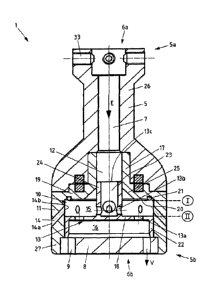
The punch foot 1 has a punch foot housing 5 which is configured so as to be
symmetrical, in particular rotationally symmetrical, about a central axis that
runs in
the extent direction E. The punch foot housing 5 in said axial extent
direction E
extends from a first housing end 5a having a first housing opening 6a to a
second
housing end 5b having a second housing opening 6b. The punch foot housing 5
here in
an exemplary manner is constructed in two parts and is composed of a first
(upper)
housing part 26 and of a second (lower) housing part 27, wherein the two
housing
parts 26 and 27 are fixedly interconnected, in particular in an airtight
manner by way
of force-fitting plug fitting, presently by a magnetic force. When required,
the second
Date Regue/Date Received 2022-05-31
CA 03003051 2018-04-24
- 17
housing part 27 that comprises the nozzles 9 and 14 is releasable from the
first
= housing part 26 in a simple and rapid manner by way of such a quick-
release
mechanism in the form of a magnetic connection.
The punch foot 1 in the region of the upper housing end 5a has a further quick-
release
mechanism 33 in the form of a plurality of spring-force-loaded bolts which are
disposed in a radial manner and rounded on the front side, on account of which
the
punch foot 1 can be plug-fitted to a punch shaft 32 in a simple way, as is
shown in fig.
3.
The interior of the punch foot 1 becomes evident in particular by means of
fig. 2.
The punch foot housing 5 thus has a pressure duct 7 which from the first
housing
opening 6a extends in the extent direction E.
The second housing opening 6b is completely filled by a perforated plate 8 and
is
closed on account of the latter, wherein a plurality of primary nozzles 9
extend in an
orientation direction V through the perforated plate 8.
Proceeding from the perforated plate 8, in particular from the internal side
(upper
side) thereof, a pressure chamber 10 which is laterally delimited by an
encircling
punch foot housing wall portion 11 extends counter to the extent direction E.
Further
to the top, that is to say counter to the extent direction E, the pressure
chamber 10 is
delimited by a wall portion 19 that runs so as to be orthogonal to the extent
direction
E and by a connection portion 12 which fluidically connects the pressure duct
7 to the
pressure chamber 10.
A control element 13 is disposed so as to be axially movable in the interior
of the
pressure chamber 10. The control element 13, by impingement by a flow, can be
reciprocated between a first terminal position I and a second terminal
position II.
Each terminal position effects another flow through the pressure chamber 10.
When
KR/hk 151845W0
July 19, 2016
CA 03003051 2018-04-24
- 18 -
the interior of the punch foot 1 is impinged with negative pressure, the
control
element 13 is thus automatically moved to the first terminal position I,
specifically
solely by the impingement by flow, or the suction force, which acts on the
control
element 13. When the interior of the punch foot 1 is impinged with positive
pressure,
the control element 13, on account thereof, is automatically moved to the
second
terminal position 11, specifically solely by the impingement by flow, or the
compressive force, respectively, which acts on the control element 13.
The punch foot housing wall portion 11 which laterally surrounds the pressure
chamber 10 has a plurality of secondary nozzles 14 which circumferentially are
disposed at identical spacings and connect the pressure chamber 10 to the
environment of the punch foot housing 5. If the control element 13 is in the
first
terminal position I, the secondary nozzles 14 on the internal side are covered
by the
control element 13 and, on account thereof, deactivated. There is no flow
through the
secondary nozzles 14 in this state. By contrast, if the control element 13 is
in the
second terminal position II, the secondary nozzles 14 are completely released
and can
be subjected to a flow through from the pressure chamber 10.
By contrast, the primary nozzles 9 that are disposed in the perforated plate 8
can be
subjected to a flow through in each of the terminal positions I and II of the
control
element 13.
As is furthermore shown in fig. 2, the secondary nozzles 14 are disposed in a
portion
of the punch foot housing 5 above the primary nozzles 9. Moreover, the
secondary
nozzles 14 lie so as to be radially further outward than the primary nozzles
9. Finally,
the secondary nozzles 14 also have another orientation (other orientation
direction)
than the primary nozzles 9. The primary nozzles 9 thus specifically run
parallel to the
extent direction E, whereas the secondary nozzles 14 have an oblique
orientation in
such a manner that the external opening 14a of each secondary nozzle 14 is
closer to
the second housing end 5b than the respective internal opening 14b of the
secondary
KR/hk 151845W0
July 19, 2016
CA 03003051 2018-04-24
- 19 -
nozzle 14. In the present exemplary embodiment the secondary nozzles 14 run at
an
angle in a range from 40 to 45 to the extent direction E.
All nozzles, both the primary nozzles 9 as well as the secondary nozzles 14,
here in an
exemplary manner are tubular ducts, in particular bores. Additionally or
alternatively,
individual or all of the nozzles 9 and 14, respectively, can also be formed by
a tube
that is extended toward the outside, and or be configured so as to be slot-
shaped.
The pressure chamber 10 by the control element 13 is subdivided into a first
(upper)
pressure chamber portion 15 and a second (lower) pressure chamber portion 16,
wherein the latter is adjacent to the perforated plate 8. The control element
13 here is
composed of a plate-shaped portion 18, of a collar-shaped portion 22 that is
disposed
thereon on the lower side, and a shaft-shaped hollow portion 23 that is
disposed
thereon on the upper side. A plurality of first connection openings 13a which
extend
through the plate-shaped portion 18 from the first pressure chamber portion 15
to the
second pressure chamber portion 16 run in the plate-shaped portion 18 so as to
be
distributed at uniform spacings across the circumference. The collar-shaped
portion
22 extends in a portion that is radially outside the first connection openings
13a that
are disposed in an annular manner. The shaft-shaped portion 23 extends
radially
within the first connection openings 13a that are disposed in an annular
manner.
The collar-shaped portion 22 is free of further openings and serves for
closing the
secondary nozzles 14 on the internal side in the first terminal position I.
The shaft-shaped portion 23 has a plurality of radial second connection
openings 13b
which are circumferentially disposed at identical spacings, presently in an
exemplary
manner four second connection openings 13b, and at the upper end of said shaft-
shaped portion 23 an opening 13c which is coaxial with the pressure duct 7.
The shaft-
shaped portion 23 is mounted so as to be movable in a further punch foot
housing
wall portion 17 that laterally delimits the connection portion 12.
Accordingly, the
KR/hk 151845W0
July 19, 2016
CA 03003051 2018-04-24
- 20 -
control element 13 on the internal side in the punch foot housing 5 is
supported by
way of the shaft-shaped portion 23 and the collar-shaped portion 22.
The connection portion 12 furthermore has a portion 25 having a funnel-shaped
cross-sectional widening, wherein the cross section of the portion 25 widens
continuously in the extent direction. The portion 25 having the cross-
sectional
widening opens into the pressure chamber 10 and in particular into the first
pressure
chamber portion 15. The portion 25 at the lower end thereof, facing the
perforated
plate 8, transitions to the wall portion 19 which closes the pressure chamber
10
toward the top.
The wall portion 19 has a wall face 20 which points toward the perforated
plate 8 and
on which an encircling protrusion 21 here in the form of an annular seal 21,
is
provided. The annular seal 21 here serves as a spacer and guarantees that a
narrow
space or gap, respectively, remains between the upper side of the plate-shaped
portion 18 and the wall face 20 of the wall portion 19 in the upper terminal
position I
of the control element 13.
In the case of the exemplary embodiment illustrated in figures 1 and 2 it is
furthermore provided in the exemplary manner that the total cross-sectional
area of
all primary nozzles 9, that is to say the sum of the individual cross-
sectional areas of
all primary nozzles 9, is greater than the total cross-sectional area, or the
sum of the
individual cross-sectional areas of all secondary nozzles 14, respectively.
Also, the
total cross-sectional area of all primary nozzles 9 is smaller than the total
cross-
sectional area of all first connection openings 13a, on the one hand, and of
all second
connection openings 13b, on the other hand. Finally, the total cross-sectional
area of
all first connection openings 13a is greater than the total cross-sectional
area of all
second connection openings 13b, the total cross-sectional area of the latter
in turn
being smaller than that of the opening 13c.
KR/hk 151845W0
July 19,2016
CA 03003051 2018-04-24
- 21 -
In the case of a negative pressure bearing on the first housing opening 6a, of
the punch
foot housing 5, the control element 13 on account of the suction force which
acts on
the control element 13, is automatically moved to the upper terminal position
I. In this
case, an airflow is initially guided by way of the primary nozzles 9 into the
second
pressure chamber portion 16, from there by way of the first connection
openings 13a
into the first pressure chamber portion 15 which is formed by a flat space
portion, the
height thereof being determined by the height of the protrusion 21, then from
here
into the portion 25 having the cross-sectional widening, then further by way
of the
second connection openings 13b into the shaft-shaped hollow portion 23, and
from
.. there into the pressure duct 7 and by way of the first housing opening 6a
back out of
the punch foot 1 again, in particular into a hollow punch shaft 32.
In the opposite case of a positive pressure bearing on the first housing
opening 6a, the
control element 13, on account of the compressive force acting thereon, is
moved to
.. the second terminal position II. A flow therethrough in this instance is
performed
from the first housing opening 6a by way of the pressure duct 7 and of an
upper
portion of the connection portion 17 into the shaft-shaped hollow portion 23,
then
from there by way of the second connection openings 13b into the first
pressure
chamber portion 15 which now is significantly enlarged as compared to the
previous
.. position. Here, the flow is divided into a first part-flow which from the
first pressure
chamber portion 15 by way of the secondary nozzles 14 exits in a first
direction into
the environment of the punch foot 1. The remaining part-flow (second part-
flow) is
guided out of the first pressure chamber portion 15 by way of the first
connection
openings 13a into the second pressure chamber portion 16 which is now reduced
in
size, and from there exits by way of the primary nozzles 9 in the other
direction into
the environment of the punch foot 1.
Fig. 3 finally shows a device 3 for labeling individual packs 4, having an
advancing
installation 28 for transporting a respective pack 4 along a transportation
path X,
having a label dispensing installation 29 for providing a printed label 30,
and having a
label application installation 31 having a label punch 2 which has a punch
shaft 32 and
KR/hk 151845W0
July 19,2016
CA 03003051 2018-04-24
- 22 -
a punch foot 1 connected thereto, wherein the label punch 2 is movable between
a
= dispensing position A in which a dispensed label 30 is able to be
suctioned by the
punch foot 1, and an application position B in which the suctioned label 30 is
able to
be blown down onto the respective pack 4.
The respective label 30 in the dispensing position A here is suctioned by the
punch
foot 1 described above exclusively by way of the primary nozzles 9 (the
control
element 13 in this position is in the first terminal position I).
The label punch 2 is subsequently lowered in the direction of the pack 4 being
guided
past the latter, and is stopped short of the upper side of the pack 4. Here, a
positive
pressure is then directed by way of the punch shaft 32 into the punch foot 1,
on
account of which the control element 13 is moved to the second terminal
position II.
This has the consequence that a compressed air pulse exits from the punch foot
1 out
of the primary nozzles 9 as well as simultaneously out of the secondary
nozzles 14,
said punch foot 1 transferring the label 30 onto the pack 4.
KR/hk 151845W0
July 19, 2016