Note: Descriptions are shown in the official language in which they were submitted.
CA 03003099 2018-04-24
WO 2017/081622
PCT/1B2016/056742
1
Capsule for beverages
The invention relates to capsules or containers for preparing products, for
example
beverages, in automatic dispensing machines. In particular, the invention
relates to a
sealed, single-dose and disposable capsule containing an initial product that
is able to
make a final product by interacting with a pressurised liquid.
Capsules are known that are intended for use in dispensing machines, that
consist of
disposable and single-dose containers comprising an outer casing, made of
plastics
impermeable to liquids and to gases and having the shape of a beaker or cup.
The casing
has a bottom wall and a side wall defining an upper opening through which the
product
-- can be inserted from which to obtain the beverage. The upper opening is
closed
hermetically by a covering element, typically a film of aluminium or of
plastics, so as to
seal the product inside the container. The covering element is generally fixed
to a
peripheral and annular flange-shaped bottom of the casing, which is opposite
the bottom
wall and arranged around the upper opening.
-- In the bottom wall a lower opening is obtained through which the beverage
is dispensed.
The lower opening is closed hermetically by a closing element, typically a
film of
aluminium or of plastics like the covering element of the upper opening.
The capsule is perforable to enable the pressurised liquid, typically water,
to be delivered
inside the capsule. In particular, the covering element is perforable by
suitable means of a
-- dispensing machine to enable pressurised liquid to be delivered into the
capsule.
The beverage is dispensed by breaking the closing element, which occurs when
the
pressure inside the capsule exceeds a preset value, depending on the
mechanical
resistance of the closing element.
One problem that occurs with this type of capsule arises from the fact that
the breakage of
-- the closing element causes a sudden change of pressure inside the capsule,
which can
trigger the so-called "water hammer", which can lead to the capsule exploding
and also to
damage to the hydraulic circuit of the dispensing machine, because the
pressure waves
generated by the water hammer can propagate in the nozzles that deliver the
pressurised
liquid to the capsule and, from the nozzles, to the entire hydraulic circuit
of the
-- dispensing machine.
A further problem that occurs with this type of capsule is due to the fact
that, when the
closing element breaks, the pressurised liquid exits from the capsule at high
speed, and
CA 03003099 2018-04-24
WO 2017/081622
PCT/1B2016/056742
2
reaching a container intended to receive the beverage can cause squirts that
exit the
container, soiling the dispensing machine and the zone surrounding the
container.
In order to overcome the aforesaid problems, capsules have been designed that
are
provided, downstream of the lower opening, with one or more labyrinth paths,
the object
of which is to decrease the speed of the beverage leaving the capsule, to
avoid the
formation of squirts when the beverage reaches the container intended to
receive the
beverage, and generate load losses that make the pressure drop less sudden,
i.e. more
progressive, inside the capsule at the moment of breakage of the closing
element of the
lower opening.
Manufacturing these labyrinth paths is nevertheless expensive and greatly
increases the
cost of manufacturing of the capsule, in addition to not fully guaranteeing
that a water
hammer does not occur when the closing element breaks.
From patent application 102014902241964, in the name of the same applicant, a
capsule
is further known in which, below the lower opening, a chamber is obtained in
which a
damping element is arranged for controlling the exit speed of the beverage.
The damping element is able to reduce, but not to eliminate completely, the
risk of a
water hammer occurring, when the closing element is broken.
One object of the present invention is to make a capsule that is usable in
known
dispensing machines that prevents the phenomenon of the water hammer occurring
when
the closing element of the lower opening of the capsule breaks and prevents
the formation
of squirts during dispensing of the beverage.
A further object is to obtain a capsule that is cheap and simple to make.
According to the invention, a capsule for beverages is provided according to
claim 1 and
one or more claims appended thereto.
The invention can be better understood and implemented with reference to the
attached
drawings that illustrate some embodiments thereof by way of non-limiting
example, in
which:
Figure 1 is a schematic cross section of a first embodiment of a capsule
according to the
invention, which is inserted into a seat of a beverage dispensing machine,
before
dispensing of the beverage starts;
Figure 2 is a section like that of Figure 1, after the start of dispensing of
the beverage;
Figure 3 is an enlarged detail of Figure 2;
Figure 4 is a cross section of only the capsule body;
CA 03003099 2018-04-24
WO 2017/081622
PCT/1B2016/056742
3
Figure 5 is a schematic view of the inside of the capsule in which a first
embodiment of
fixing of the lower closing element is highlighted;
Figure 6 is a view like that of Figure 5 highlighting a line of tearing of the
lower closing
element, through the effect of the pressure of the liquid delivered into the
capsule;
Figure 7 is a cross section of a second embodiment of a capsule according to
the
invention, inserted into a seat of a beverage dispensing machine, before
dispensing of the
beverage starts;
Figure 8 is a section like that of Figure 7, after the start of dispensing of
the beverage;
Figures 9 and 10 are views like those of Figure 5 that illustrate respectively
a second and
a third embodiment of fixing of the lower closing element;
Figure 11 is a cross section of a third embodiment of a capsule according to
the invention,
inserted into a seat of a beverage dispensing machine, before dispensing of
the beverage
starts;
Figure 12 is a section like that of Figure 11, after the start of dispensing
of the beverage;
Figure 13 is an enlarged detail of Figure 12;
Figure 14 is a cross section of a fourth embodiment of a capsule according to
the
invention, inserted into a seat of a beverage dispensing machine, before
dispensing of the
beverages starts;
Figure 15 is a section like that of Figure 14, after the start of dispensing
of the beverage;
Figure 16 is an enlarged detail of Figure 15;
Figure 17 is the section XVII-XVII of figure 15;
Figure 18 is a cross section of a fifth embodiment of a capsule according to
the invention;
Figure 19 is the section XIX- XIX of Figure 18;
Figure 20 is fragmentary, perspective and partially sectioned view of the
capsule of
Figure 18;
Figure 21 is another fragmentary, perspective and partially sectioned view of
the capsule
of Figure 18;
Figure 22 is a further fragmentary, perspective view of the capsule of Figure
18;
Figures 23, 24 and 25 are perspective views from different points of view of a
detail of
Figure 18;
Figure 26 is an enlarged detail of Figure 18,
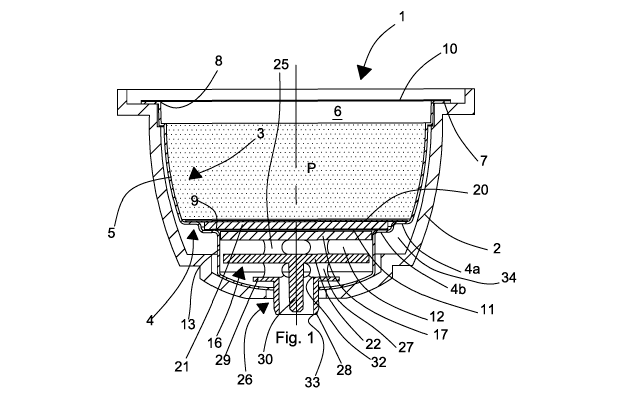
In Figures 1 to 6 a first embodiment is illustrated of a capsule 1 for
beverages according
to the invention, usable in an automatic dispensing machine for producing a
final product,
CA 03003099 2018-04-24
WO 2017/081622
PCT/1B2016/056742
4
in particular a hot beverage, for example coffee, barley, herbal tea, tea,
chocolate, etc., by
injecting a hot pressurised fluid, for example water, thereinto. The capsule 1
is inserted
into a seat 2 of the automatic dispensing machine of a system for preparing a
beverage.
The capsule 1 according to the invention comprises an outer casing or
container 3, in turn
comprising a base wall 4 and a first portion of side wall 5 defining a cavity
6 that is open
and suitable for containing an initial product P, for example a soluble or
percolable food
product to be combined with a fluid, typically water, to obtain a final
product in the form
of a beverage. The base wall 4 and the first portion of side wall 5 define a
body of the
capsule 1 that is substantially beaker or cup-shaped.
The base wall 4 comprises an annular first shoulder 4a, linked to the first
portion of side
wall 5 and an annular second shoulder 4b. The annular second shoulder 4b has
smaller
dimensions than dimensions of the annular shoulder 4a and is placed below the
annular
first shoulder 4a and is linked thereto, as represented in the figures.
The casing further comprises an upper edge 7 in the shape of a flange
connected to the
first portion of side wall 5 and extending therefrom, arranged around a first
opening 8 of
the cavity 6, opposite the base wall 4. The upper edge 7 is also opposite the
base wall 4
and faces outside with respect to the cavity 6.
In the base wall 4 a second opening 9 is obtained, through which the beverage
prepared
from the initial product P can exit the cavity 6.
The casing 3 is in fact made by forming a sheet of thermoformable plastic
material that is
suitable for the process of preparing the final product from the initial
product, for example
able to bear without deformation temperatures up to 100 C and pressure up to
at least 5
bar.
This sheet of plastics can have a thickness comprised between 15 micron and
1400 micron,
in particular between 350 micron and 1200 micron and is made of a polyolefin,
for
example polypropylene PP and/or polyethylene PE and/or polyamide PA.
In detail, the sheet material can comprise a first layer of material, in
particular suitable for
contacting and/or preserving the initial product P, for example made of
polypropylene PP
that is impermeable to humidity, a second layer of material that is not in
contact with the
initial product P made of gas-impermeable material, in particular impermeable
to oxygen
and optionally also to humidity, also known as a barrier layer, and a third
layer of external
material.
The barrier layer, interposed between the first and second layer, ensures
complete
CA 03003099 2018-04-24
WO 2017/081622
PCT/1B2016/056742
insulation of the external environment of the cavity 6, in particular if the
first layer is
permeable over time to oxygen. The barrier layer has a thickness comprised
between 2
micron and 100 micron, in particular between 15 micron and 70 micron, and is
made for
example of ethylene vinyl alcohol (EVOH), which is gas-impermeable only to
oxygen or
5 polyvinylidene chloride (PVDC), which is gas-impermeable to both oxygen
and to
humidity.
According to a first embodiment (which is not shown) of the sheet material,
the first and
third layer are made of the same material, for example polypropylene PP and
are coupled
with the barrier layer that is interposed therebetween. Such layers can have
the same
thickness (for example 350 micron), or different thicknesses (for example the
first layer
can have a thickness of 500 micron whereas the third layer can have a
thickness of 300
micron).
According to a second embodiment (which is not shown), the first layer is a
support and is
made of polypropylene PP, the second layer is the barrier layer (EVOH or PVDC)
and the
third layer is an extruded layer of polypropylene PP or polyethylene PE, of
thickness that is
equal to 15 micron, which is coupled with the first and the second layer
during the process
of producing the sheet material.
The sheet material, both according to the first and the second embodiment, is
then selected
in such a manner as to protect over time the initial product P contained in
the capsule from
humidity and oxygen.
The capsule further comprises a covering element 10 fixed to the upper edge 7
of the
casing 3 for hermetically closing the first opening 8 of the cavity 6. The
covering element
10 comprises an aluminium film or a film of plastics provided with a barrier
layer that is
perforable by injecting means (that is not shown) by means of which a
pressurised liquid,
for example water, is injected inside the cavity 6 to produce the beverage.
The covering element 10 is fixed to the upper edge 7 of the casing 3 by heat
or ultrasound
welding, or by gluing. Preferably the covering element 10 is fixed to the
casing 3 by heat
welding.
The second opening 9, preferably of circular shape, in the base wall 4 is also
closed
hermetically by a closing element 11, which is similar to the covering element
10. A
peripheral zone lla of the closing element 11 is fixed to the second shoulder
4b of the base
wall 4, inside the cavity 6, by a first heat or ultrasound weld Sl, or by
gluing.
The covering element 10 and the closing element 11 close the cavity 6
hermetically and
CA 03003099 2018-04-24
WO 2017/081622
PCT/1B2016/056742
6
preserve the initial product P contained therein.
The closing element 11 is intended to tear when, following the delivery of
pressurised
liquid into the cavity 6, the pressure inside the cavity 6 exceeds a preset
value, depending
on the mechanical resistance of the material of which the closing element 11
is made.
Tearing the closing element 11 causes the beverage to exit the cavity 6 and
the subsequent
dispensing thereof into a container intended to receive the beverage, for
example a cup or a
glass, as will be explained in greater detail below.
In the lower part of the cavity 6 a first filtering element 20 is arranged,
for example made
of paper, fixed, for example by gluing, to the first shoulder 4a of the base
wall 4, and a
second filtering element 21, for example made of nonwoven fabric, which rests
on the
second shoulder 4b of the base wall 4, above the closing element 11. The first
filtering
element 20 and the second filtering element 21 prevent particles of the
product P being
able to be dispensed together with the beverage, when the product P is not a
soluble
product, such as, for example, coffee powder.
It is advantageous for the second filtering element 21 to have great
resistance to
deformation, such that it does not get significantly deformed through the
effect of the
pressure that develops in the cavity 6 when a pressurised liquid is delivered
thereinto to
prepare the beverage.
Under the base wall 4, as represented in the figures, a chamber 12 is defined
that can
communicate with the cavity 6 through the second opening 9. The chamber 12 is
defined
by a second portion 13 of side wall and by a bottom wall 14, in the centre of
which a third
opening 15 is made. The chamber 12 has a cross section of preferably circular
shape, but
can also have a different section from the circular section, for example an
elliptical section
or polygonal section or lobed section.
Inside the chamber 12 a damping element 16 is arranged, the function of which
is to
control the exit speed of the beverage, in particular to prevent the
phenomenon of water
hammer at the moment of tearing of the closing element 11, preventing pressure
waves
forming that are generated by the aforesaid phenomenon, which could cause the
capsule to
explode and also damage to the hydraulic circuit of the dispensing machine.
The damping element 16 also performs the function of preventing the formation
of squirts
during the dispensing of the beverage into a container.
The damping element 16 comprises a disc-shaped upper part 17, with a
preferably
rectangular cross section, so dimensioned that between an outer edge 18
thereof and the
CA 03003099 2018-04-24
WO 2017/081622
PCT/1B2016/056742
7
second portion of side wall 13 a first passage 19 (Figure 3) is defined having
a width that is
sufficient to enable the damping element 16 to slide inside the chamber 12,
but as to slow
significantly the speed of the beverage passing therethrough and generate a
significant
pressure difference between the inlet and the outlet of the passage 19.
Preferably, the width
of the passage 19 is not greater than 1 mm.
The damping element 16 further comprises a lower part 22, which is also disc-
shaped, with
a preferably rectangular cross section, dimensioned in such a manner that
between the
outer edge 23 thereof and the second portion of side wall 13 a second passage
24 is defined
having a width that is significantly greater than the width of the passage 19
sufficient to
enable the beverage to pass without generating significant load losses. The
upper part 17
and the lower part 22 of the damping element 16 are connected together by
first connecting
elements 25, which are, for example, column-shaped.
The damping element 16 further comprises a dispensing element 26 through which
the
beverage is dispensed that is prepared with the product P contained in the
cavity 6 of the
capsule 1.
The dispensing element 26 is fixed below the lower part 22 by second
connecting elements
27, which are also, for example, column-shaped.
The dispensing element 26 comprises a hollow cylindrical body 28, provided
above with
an annular edge 29 protruding outside of the hollow cylindrical body 28.
The hollow cylindrical body 28 is provided with an inlet opening 32 through
which the
beverage can enter therein and with an outlet opening 33 through which the
beverage can
exit the capsule 1. The hollow cylindrical body 28 is inserted into the third
opening 15 in
the centre of the bottom wall 14 of the capsule 1.
The outer diameter of the hollow cylindrical body 28 is selected in such a
manner that the
hollow cylindrical body 28 is coupled with slight interference with the third
opening 15,
such that a seal is assured against leaking of liquid between the hollow
cylindrical body 28
and the bottom wall 14 of the capsule 1, but the hollow cylindrical body 28 is
not
prevented from sliding into the third opening 15 if a thrust is applied to the
damping
element 16 that is sufficient to overcome the friction resistance between the
hollow
cylindrical body 28 and the bottom wall 14.
The lower part 22 of the damping element 16 is provided below with an
elongated
protrusion 30 that extends inside the hollow cylindrical body 28 of the
dispensing element
26 and guides the flow of the beverage such as to prevent squirts during
dispensing.
CA 03003099 2018-04-24
WO 2017/081622
PCT/1B2016/056742
8
The closing element 11, which, as already said, is fixed peripherally to the
second shoulder
4b of the base wall 4, is further fixed at a central zone 1 lb thereof, by a
second weld S2,
preferably a heat weld, to the upper part 17 of the damping element 16. The
second weld
S2 is made on the entire surface of the central zone 1 lb. Between the
peripheral zone 11 a
and the central zone llb of the closing element 11 an annular zone 11c can be
defined that
is devoid of welding and straddles the first passage 19 between the upper part
17 of the
damping element 16 and the second portion of side wall 13. The width of the
annular zone
11c can also be substantially the same as the width of the first passage 19.
To prepare a beverage with the product P contained in the capsule 1 and
dispense the
beverage into a container, the injectors of the dispensing machine into which
the capsule 1
is inserted perforate the covering element 10 and deliver into the cavity 6 of
the capsule a
pressurised liquid, for example water, which is mixed with the product P.
The pressurised liquid exerts a thrust on the closing element 11 and on the
damping
element 16 below. When the value of said thrust exceeds the friction
resistance between
the hollow cylindrical body 28 and the bottom wall 14 of the capsule 1, the
damping
element 16 moves downwards, moving from an initial position shown in Figure 1
as far as
a final position, shown in Figure 2, in which the annular edge 29 of the
dispensing element
26 rests on the bottom wall 14 of the capsule 1.
During the aforesaid movement, the damping element 16 drags with itself
downwards the
central zone 1lb of the closing element 11, which is fixed to the upper part
17 of the
damping element 16, whilst the peripheral zone lla does not move, being fixed
to the base
wall 4. This generates progressively increasing dragging stress that causes
breaking of the
closing element 11 along a fracture line 31.
Following breakage of the closing element 11 the pressurised beverage
contained in the
cavity 6 enters the chamber 12 and starts to filter through the first passage
19 and then
traverses the second passage 24 and enters the hollow cylindrical body 28,
passing through
the inlet opening 32 and exits the capsule 1 through the outlet opening 33.
When the beverage starts to filter through the passage 19, the pressure
thereof determines a
thrust on the second portion 13 of side wall of the capsule 1. In the seat 2
of the dispensing
machine into which the capsule is inserted a space 34 is provided that
surrounds the second
portion 13 of side wall so as to enable said second portion 13 to get
progressively
deformed outwards, thus widening the passage 19 so as to make the transit
easier of the
beverage through, without nevertheless causing a sudden fall in pressure in
the chamber 6
CA 03003099 2018-04-24
WO 2017/081622
PCT/1B2016/056742
9
of the capsule 5, such that the phenomenon of the water hammer is securely
avoided.
When the pressure inside the cavity 6 starts to decrease through the effect of
the
progressive passage of the beverage into the chamber 12 below, the deformation
of the
second portion 13 of side wall starts to decrease and the first passage 19
starts to shrink
until it returns to the initial dimensions. At this point, in general, the
pressure in the
chamber 6 is no longer sufficient to overcome the load losses in the first
passage 19, which
cases the end of dispensing of the beverage.
In Figures 7 to 10 a second embodiment of a capsule according to the invention
is shown,
indicated by the reference number la.
In this second embodiment, in the upper part 17 of the damping element 16, in
a
substantially central position, a through hole 35 is provided. Further, the
central zone 1 lb
of the closing element 11 is fixed to the upper part 17 of the damping element
16 with a
spot weld S3.
For the rest, the capsule 1 a is identical to the capsule 1 according to the
first embodiment
illustrated in Figures 1 to 6.
When the damping element 16 is pushed downwards by the pressure of the
beverage in the
cavity 6 the parts of the central zone 1 lb of the closing element 11 that are
not affected by
the spot weld S3 separate from the upper part 17 of the damping element 16
creating
passages that, when the fracture of the closing element 11 occurs, enable the
beverage to
enter the chamber 12 also through the through hole 35. This enables complete
emptying of
the cavity 6 to be obtained, because the beverage can continue to pass from
the cavity 6 to
the chamber 12 even when the pressure inside the cavity 6 is no longer
sufficient to pass
the beverage through the first passage 19.
In Figure 10 a version is illustrated of the fixing of the closing element 11
to the upper part
17 of the damping element 16. In this version, the central zone lib of the
closing element
11 is fixed to said upper part 17 by a plurality of substantially radial welds
S4.
When the damping element 16 is pushed downwards by the pressure of the
beverage in the
cavity 6 the parts of the central zone 1 lb of the closing element 11 that are
not affected by
the radial welds S4 separate from the upper part 17 of the damping element 16
creating
passages, that, when the fracture of the closing element 11 occurs, enable the
beverage to
enter the chamber 12 also through the through hole 35, thus making possible
complete
emptying of the cavity 6, as disclosed above.
In Figures 11 to 13 a third embodiment is illustrated of a capsule according
to the
CA 03003099 2018-04-24
WO 2017/081622
PCT/1B2016/056742
invention, indicated by the reference number lb.
This third embodiment differs from the first and second embodiment disclosed
in Figures 1
to 10 through the fact that instead of the first filtering element 20 and of
the second
filtering element 21 a single filtering element 36 is provided consisting of a
disc, for
5 example made of plastics, in which a plurality of through holes is made,
the dimensions of
which are selected in such a manner as to enable the beverage to pass, but to
prevent the
passage of solid particles, for example coffee powder, to prevent the latter
being able to be
dispensed together with the beverage.
For the rest, the capsule lb is identical to the capsule 1 illustrated in
Figures 1 to 6, or to
10 the capsule la, illustrated in Figures 7 to 10.
In Figures 14 to 17 a fourth embodiment of a capsule according to the
invention is
illustrated, indicated by the reference number lc.
This fourth embodiment differs from the other embodiments illustrated in
Figures 1 to 13,
through the fact that the second portion 13 of side wall has a lobed shape
with a plurality of
portions 37 protruding outwards. At these protruding portions 37, the first
passage 19 and
the second passage 24 have respective widenings 38, which, in the case of a
beverage that
contains solid or semisolid elements, such as a soup for example, enable these
solid
elements to pass and be dispensed together with the beverage and/or
substantially prevent
the formation of foam.
For the rest, the capsule 1 c is identical to the capsule 1 illustrated in
Figures 1 to 6, or to
the capsule la, illustrated in Figures 7 to 10, or to the capsule lb
illustrated in Figures 11 to
13.
In further embodiment, which is not shown, of the capsule according to the
invention the
closing element 11 is not fixed to the upper part 17 of the damping element
16.
In this further embodiment, when a pressurised liquid is delivered into the
chamber 6, the
closing element 11 is deformed in the direction of the damping element 16 and
moves the
latter between said first position and said second position, remaining resting
on the first
part 17 of the damping element 16. The deformation of the closing element 11
causes
pulling stress on the element that causes the closing element 11 to tear when
the
mechanical resistance of the material of which the closing element 11 is made
is exceeded.
The distance between the first position and second position of the closing
element 11 is
selected in such a manner that tearing of the closing element 11 can occur
before the
damping element 16 reaches said second position.
CA 03003099 2018-04-24
WO 2017/081622
PCT/1B2016/056742
11
After tearing of the closing element 11 has occurred, the beverage is
dispensed as disclosed
previously.
In Figures 18 to 26 a fifth embodiment is shown of a capsule according to the
invention,
indicated by the reference number Id.
Similarly to the other embodiments of capsules according to the invention, the
capsule id
according to the invention comprises an outer casing or container 3, in turn
comprising a
base wall 4 and a first portion of side wall 5 defining a cavity 6 that is
open and suitable for
containing an initial product P, for example a soluble or percolable food
product to be
combined with a fluid, typically water, to obtain an end product in the form
of a beverage.
The base wall 4 and the first portion of side wall 5 define a body of the
capsule id that is
substantially beaker or cup-shaped.
The base wall 4 comprises an annular first shoulder 4a, linked to the first
portion of side
wall 5 and an annular second shoulder 4b. The annular second shoulder 4b can
have
smaller dimensions than dimensions of the annular shoulder 4a, is placed below
the
annular first shoulder 4a and is linked thereto, as represented in the
figures.
The casing further comprises a flange-shaped upper edge 7 connected to the
first portion
of side wall 5 and extending therefrom, arranged inside a first opening 8 of
the cavity 6,
opposite the base wall 4. The upper edge 7 is also opposite the base wall 4
and faces
outside with respect to the cavity 6.
In the base wall 4 a second opening 9 is obtained, through which the beverage
prepared
from the initial product P can exit the cavity 6.
The capsule further comprises a covering element 10 fixed to the upper edge 7
of the
casing 3 to close hermetically the first opening 8 of the cavity 6. The
covering element 10
comprises a film of aluminium or of plastics provided with a barrier layer
that is perforable
by injection means (which is not shown) by means of which a pressurised
liquid, for
example water, is injected inside the cavity 6 to produce the beverage.
The covering element 10 is fixed to the upper edge 7 of the casing 3 by heat
or ultrasound
welding or gluing. Preferably, the covering element 10 is fixed to the casing
3 by heat
welding.
The second opening 9, which is preferably of circular shape, in the base wall
4 is also
closed hermetically by a closing element 11, which is similar to the covering
element 10. A
peripheral zone lla of the closing element 11 is fixed to the second shoulder
4b of the base
wall 4, inside the cavity 6, by heat or ultrasound welding or by gluing.
CA 03003099 2018-04-24
WO 2017/081622
PCT/1B2016/056742
12
The covering element 10 and the closing element 11 close hermetically the
cavity 6 and
preserve the initial product P contained therein.
The closing element 11 is intended to tear when, following the delivery of
pressurised
liquid into the cavity 6, the pressure inside the cavity 6 exceeds a preset
value, depending
on the mechanical resistance of the closing element of which the closing
element 11 is
made. The tearing of the closing element 11 determines the exit of the
beverage from the
cavity 6 and the subsequent dispensing thereof into a container intended to
receive the
beverage, for example a cup or a beaker.
In the lower part of the cavity 6 a first filtering element 20 is arranged,
which is for
example made of paper, which is fixed, for example by gluing, on the first
shoulder 4a of
the base wall 4. A second filtering element can be provided, which is not
shown, which is
similar to the second filtering element 21 disclosed above, arranged in the
same position of
the second filtering element 21. The first filtering element 20 and the
possible second
filtering element 21 prevent the particles of product P being able to be
dispensed together
with the beverage, when the product P is not a soluble product, such as, for
example,
coffee powder.
Under the base wall 4, a chamber 12 is defined that can communicate with the
cavity 6
through the second opening 9. The chamber 12 is defined by a second portion 13
of side
wall and by a bottom wall 14, in the centre of which a third opening 15 is
made. The
chamber 12 has a cross section of preferably circular shape but can also have
section that is
different from the circular section, for example an elliptical or polygonal or
lobed section.
Inside the chamber 12, a damping element 16a is arranged which is a version of
the
damping element 16 shown in figures 1 to 17.
Similarly to what has been illustrated previously, the function of the damping
element 16a
is to control the exit speed of the beverage, in particular to prevent the
phenomenon of
water hammer at the moment of tearing of the closing element 11, preventing
pressure
waves forming that are generated by the aforesaid phenomenon, which could
cause the
capsule to explode and also damage the hydraulic circuit of the dispensing
machine.
The damping element 16a also performs the function of preventing squirts
during
dispensing of the beverage into a container.
The damping element 16a comprises a disc-shaped upper part 17, with a
preferably
rectangular cross section, dimensioned in such a manner that between an outer
edge 18
thereof and the second portion 13 of side wall there is defined a first
passage 19 (Figure
CA 03003099 2018-04-24
WO 2017/081622
PCT/1B2016/056742
13
26) having sufficient width to enable the damping element 16a to slide inside
the chamber
12, but such as to slow significantly the speed of the beverage that passes
therethrough and
generate a significant pressure difference between the inlet and the outlet of
the passage
19. Preferably the width of the passage 19 is not greater than 1 mm.
The damping element 16a further comprises a lower part 22, which is also disc-
shaped,
with a preferably rectangular cross section on an outer edge 23 of which
second passages
39 are obtained in the form of recesses of said outer edge 23 that are so
dimensioned as to
permit the passage of the beverage without generating significant load losses.
In the
embodiment illustrated in Figures 18 to 26, the openings 39 are four in
number, distributed
regularly along the outer edge 23 of the lower part 22. Nevertheless, the
openings can be
fewer or more in number than four and be arranged along the outer edge 23,
without falling
outside the scope of the present invention.
The upper part 17 and the lower part 22 of the damping element 16a are
connected together
by first connecting elements 40, 41 comprising a central connecting element 40
in the
shape of a column arranged substantially along a diameter of the upper part 17
and of the
lower part 22, and by two lateral connecting elements 41, which also have the
shape of
columns or ribs, parallel to the first connecting element 40 and arranged on
sides opposite
the first connecting element 40. The upper part 17 and the lower part 22 are
further
connected together by a third connecting element 44, that intersects the first
connecting
elements 40, 41, for example it is substantially perpendicular to the first
connecting
elements 40, 41. The first connecting element 40, the further connecting
elements 41 and
the third connecting element 44 preferably have a length that is less than the
diameter of
the upper part 17 and of the lower part 22 of the damping element 16a, such as
to enable
the beverage to circulate freely between said upper part 17 and said lower
part 22.
Between the upper part 17 and the lower part 22 of the damping element 16a a
space 42 is
defined into which the beverage flows that passes through the first passage
19, before
entering the second passages 39.
The damping element 16a lastly comprises a dispensing element 26 through which
the
beverage is dispensed that is prepared with the product P contained in the
cavity 6 of the
capsule 1.
The dispensing element 26 is fixed below the lower part 22 by second
connecting elements
27, which also, for example, have the shape of columns.
The dispensing element 26 comprises a hollow cylindrical body 28, provided
above with
CA 03003099 2018-04-24
WO 2017/081622
PCT/1B2016/056742
14
an annular edge 29 protruding outside the hollow cylindrical body 28.
The hollow cylindrical body 28 is provided with an inlet opening 32 through
which the
beverage can enter therein and with an outlet opening 33 through which the
beverage can
exit the capsule 1. The hollow cylindrical body 28 is inserted into the third
opening 15 in
the centre of the bottom wall 14 of the capsule 1.
The outer diameter of the hollow cylindrical body 28 is chosen in such a
manner that the
hollow cylindrical body 28 can couple with slight interference with the third
opening 15, in
such a manner that a seal is assured against leaking of liquid between the
hollow
cylindrical body 28 and the bottom wall 14 of the capsule 1, but the hollow
cylindrical
body 28 is not prevented from sliding into the third opening 15 if a thrust is
applied to the
damping element 16a that is sufficient to overcome the friction resistance
between the
hollow cylindrical body 28 and the bottom wall 14.
Inside the hollow cylindrical body 28 a baffle 43 is arranged, having a width
L (Fig. 24)
that is equal to about the internal radius r (Fig. 19) of the hollow
cylindrical body 28 and
extending for about the entire length of the hollow cylindrical body 28. The
baffle 43
reduces substantially the turbulence of the beverage exiting the capsule Id,
such as to
avoid squirts whilst the beverage is dispensed into a suitable container.
The operation of the capsule Id according to the fifth embodiment illustrated
in Figures
18 to 26 is identical to the operation of the other embodiments of a capsule
according to
the invention disclosed in Figures 1 to 17.