Note: Descriptions are shown in the official language in which they were submitted.
CA 03003403 2018-04-26
WO 2017/078659 PCMJS2015/058548
GLASS SHEET FORMING SYSTEM
TECHNICAL FIELD
[0001] This invention relates to a glass sheet forming system for forming
glass sheets.
BACKGROUND
[0002] Glass sheets are conventionally formed by heating on a conveyor
within a furnace
and then in one mode are formed within a heated chamber prior to delivery for
cooling. Such
cooling can be slow cooling to provide annealing or faster cooling that
provides heat strengthening
or tempering. In connection with heating of the glass sheets, see United
States Patents: 3,806,312
McMaster et al.; 3,947,242 McMaster et al.; 3,994,711 McMaster; 4,404,011
McMaster; and
4,512,460 McMaster. In connection with glass sheet forming, see United States
Patents: 4,204,854
McMaster et al.; 4,222,763 McMaster; 4,282,026 McMaster et al.; 4,437,871
McMaster et al.;
4,575,390 McMaster; 4,661,141 Nitschke et al.; 4,662,925 Thimons et al.;
5,004,491 McMaster et
al.; 5,330,550 Kuster et al.; 5,376,158 Shetterly et al.; 5,472,470 Kormanyos
et al.; 5,900,034
Mumford et al.; 5,906,668 Mumford et al.; 5,925,162 Nitschke et al.; 6,032,491
Nitschke et al.;
6,173,587 Mumford et al.; 6,227,008 Shetterly; 6,418,754 Nitschke et al.;
6,543,255 Bennett et al.;
6,578,383 Bennett et al.; 6,718,798 Nitschke et al.; 6,729,160 Nitschke et al.
In connection with the
cooling, see United States Patents: 3,936,291 McMaster; 4,470,838 McMaster et
al.; 4,525,193
McMaster et al.; 4,946,491 Barr; 5,385,786 Shetterly et al.; 5,917,107 Ducat
et al.; 6,079,094 Ducat
et al.; and 6,513,348 Bennett et al.
[0003] One conventional way glass sheets are formed is by heating and
conveyance on a
conveyor into a heated forming station that has a forming mold located within
the heated chamber
above the conveyor. Conventionally, electrical limit switches that are
mechanically actuated or
electric eyes are utilized to initiate upward transfer of the heated glass
sheet from the conveyor to a
downwardly oriented curved forming face of the mold. The mechanical actuation
of the electric
limit switches thus must function effectively in the heated environment as
must the electric eyes
which have electromagnetic beams whose sensing signals the glass presence to
initiate the upward
transfer. However, the heat in the chamber can affect actuation of the
electrical limit switches and
their mechanical actuation and can also affect the electric eye beams. In
prior commercial use that
1
has not been available to the public, a fluid switch has previously been
mounted in the
heated interior of the system to sense the conveyed glass sheet location and
actuate the
forming cycle. This actuation previously has immediately actuated the cycle
for glass sheet
transfer from a roller conveyor to an upper mold, which necessitates the fluid
switch being
located adjacent the forming apparatus and not spaced therefrom so as not to
interfere with
the forming apparatus operation.
SUMMARY
[0004] According to one aspect of the present invention, an object is to
provide in a glass
sheet forming system including a housing having a heated clamber and a roller
conveyor
including rollers for conveying a hot glass sheet within the heated chamber
along a direction
of conveyance in a horizontal plane in preparation for forming, a location
sensing assembly
for sensing the location of a leading extremity of the glass sheet along the
direction of
conveyance, comprising:
a frame supported by the housing to extend laterally with respect to the
direction of
conveyance in the heated chamber at a location below the horizontal plane
along which the
glass sheet is conveyed;
a carriage mounted by the frame for lateral movement with the respect to the
direction of conveyance;
a fluid switch that is mounted by the carriage and that is actuated by the
conveyed
glass sheet to provide a glass position sensing signal; and
a lateral positioner having: an inner connection to the carriage within the
heated
chamber; and an outer operating portion located outside the housing for
operation to move
the carriage laterally with respect to the direction of conveyance to
laterally align the fluid
switch with the leading extremity of the conveyed glass sheet for the
actuation that provides
the glass position sensing signal for providing glass sheet positioning during
the forming.
[0004a] According to another aspect of the present invention, an object is to
provide in a
glass sheet forming system including a housing having a heated clamber and a
roller
conveyor including rollers for conveying a hot glass sheet within the heated
chamber along a
2
CA 3003403 2019-11-29
direction of conveyance in a horizontal plane in preparation for forming, a
location sensing
assembly for sensing the location of a leading extremity of the glass sheet
along the
direction of conveyance, comprising:
a frame supported by the housing to extend laterally with respect to the
direction of
conveyance in the heated chamber at a location below the horizontal plane
along which the
glass sheet is conveyed;
a carriage mounted by the frame for lateral movement with the respect to the
direction of conveyance;
a fluid switch that is mounted by the carriage and that is actuated by the
conveyed
glass sheet to provide a glass position sensing signal; and
a lateral positioner having a shaft including an inner connection to the
carriage within
the heated chamber and an outer operating end located outside the housing and
having a
handle for moving the carriage laterally with respect to the direction of
conveyance to
laterally align the fluid switch with the leading extremity of the conveyed
glass sheet for the
.. actuation that provides the glass position sensing signal for providing
glass sheet positioning
during the forming, and an inner end of the shaft also having a lock for
locking the carriage
to prevent lateral movement thereof with respect to the direction of
conveyance after the
fluid switch is laterally aligned with the leading extremity of the glass
sheet.
[0004b] According to yet another aspect of the present invention, an object is
to provide in a
glass sheet forming system including a housing having a heated clamber and a
roller
conveyor including rollers for conveying a hot glass sheet within the heated
chamber along a
direction of conveyance in a horizontal plane in preparation for forming, a
location sensing
assembly for sensing the location of a leading extremity of the glass sheet
along the
direction of conveyance, comprising:
a frame supported by the housing to extend laterally with respect to the
direction of
conveyance in the heated chamber at a location below the horizontal plane
along which the
glass sheet is conveyed;
a carriage mounted by the frame for lateral movement with the respect to the
.. direction of conveyance;
2a
CA 3003403 2019-11-29
a fluid switch that is mounted by the carriage and that is actuated by the
conveyed
glass sheet to provide a glass position sensing signal;
a lateral positioner having a shaft including an inner connection to the
carriage within
the heated chamber and an outer operating end located outside the housing and
having a
handle for moving the carriage laterally with respect to the direction of
conveyance to
laterally align the fluid switch with the leading extremity of the conveyed
glass sheet for the
actuation that provides the glass position sensing signal for providing glass
sheet positioning
during the forming, and an inner end of the shaft also having a lock including
an eccentric for
locking the carriage by handle rotation of the shaft to prevent lateral
movement of the
carriage and the fluid switch with respect to the direction of conveyance
after the fluid switch
is laterally aligned with the leading extremity of the glass sheet; and
a wedge that vertically moves a lateral end of the frame to provide vertical
positioning
of the fluid switch.
[0004c] Other possible aspect(s), object(s), embodiment(s), variant(s) and/or
advantage(s)
of the present invention, all being preferred and/or optional, are briefly
summarized
hereinbelow.
[0004d] For example, an object of the present invention can be to provide an
improved
glass sheet forming system.
[0005] In carrying out the above object, the glass sheet forming system of the
invention
includes a housing having a heated clamber and a roller conveyor including
rollers for
conveying a hot glass sheet within the heated chamber along a direction of
conveyance in a
horizontal plane in preparation for forming. A location sensing assembly of
the system
senses the location of the leading extremity of the glass sheet along the
direction of
conveyance and includes a frame supported by the housing to extend laterally
with respect
to the direction of conveyance in the heated chamber at a location below the
horizontal
plane along which the glass sheet is conveyed. A carriage of the location
sensing assembly
is mounted by the frame for lateral movement with the respect to the direction
of
conveyance, and a fluid switch is mounted by the carriage and is actuated by
the conveyed
2b
CA 3003403 2019-11-29
glass sheet to provide a glass position sensing signal. A lateral positioner
of the location
sensing assembly has: an inner connection to the carriage within the heated
chamber; and
an outer operating portion located outside the housing for operation to move
the carriage
laterally with respect to the direction of conveyance to laterally align the
fluid switch with the
leading extremity of the conveyed glass sheet for the actuation that provides
the glass
position sensing signal for providing glass sheet positioning during the
forming.
[0006] As disclosed, the lateral positioner includes a shaft having: an inner
end connected to
the carriage; and an outer end having a handle for moving the carriage and the
fluid switch
mounted thereon laterally with respect to the direction of conveyance into
alignment with the
leading extremity of the glass sheet. The inner end of the shaft has a lock
for locking the
carriage to prevent lateral movement thereof with respect to the direction of
conveyance
after the fluid switch is
2c
CA 3003403 2019-11-29
CA 03003403 2018-04-26
WO 2017/078659 PCT/US2015/058548
laterally aligned with the leading extremity of the glass sheet, and the
handle on the outer end of the
shaft operates the lock. More specifically, the lock includes an eccentric and
the handle is rotated to
rotate the shaft and thereby lock the eccentric against the frame to prevent
the carriage from moving
laterally with respect to the direction of conveyance.
[0007] As disclosed, the location sensing assembly includes a vertical
adjuster for vertically
adjusting the frame to vertically position the fluid switch with respect to
the horizontal plane along
which the glass sheet is conveyed. More specifically the vertical adjuster
includes a wedge that
vertically moves a lateral end of the frame to provide the vertical
positioning of the fluid switch.
[0008] As disclosed, the fluid switch includes: a vacuum chamber in which a
vacuum is
drawn; a valve member having a closed position that closes an atmospheric port
of the vacuum
chamber and has an actuating portion that is contacted by the leading
extremity of the conveyed
glass sheet to move the valve member from the closed position to an open
position with respect to
the atmospheric port so air flows into the vacuum chamber to increase its
pressure; a transducer that
is located externally of the heated chamber and senses the pressure increase
in the vacuum chamber
to provide an electric glass position sensing signal for controlling the
forming; and a pressure port to
which pressurized air is supplied to move the valve member from the open
position with respect to
the atmospheric port to the closed position in preparation for another cycle
of operation.
[0009] The objects, features and advantages of the present invention are
readily apparent
from the following detailed description of the preferred embodiment when taken
in connection with
the accompanying drawings.
BRIEF DESCRIPTION OF THE DRAWINGS
[0010] FIGURE 1 is a schematic top plan view of a glass sheet forming
system that
embodies the present invention.
[0011] FIGURE 2 is a schematic side elevational view of the forming system
taken along the
direction of line 2-2 in Figure 1.
3
CA 03003403 2018-04-26
WO 2017/078659 PCT/US2015/058548
[0012] FIGURE 3 is a schematic elevational end view of the forming system
taken along the
direction of line 3-3 in Figure 1 and illustrates a forming station having
first and second forming
sections with forming molds utilized to provide glass sheet forming within the
heated environment
of the system.
[0013] FIGURE 3a is a partial elevation view showing the right second
forming section of
the forming station of Figure 3 after an initially formed glass sheet has been
moved thereto on a first
upper mold from the left first forming station to a position above a lower
mold and below a second
upper mold that has released a formed glass sheet from a prior cycle onto a
delivery mold that is
subsequently moved out of the forming station for delivery.
[0014] FIGURE 3b is another partial view of the right second forming
section of the forming
station of Figure 3 showing the glass sheet during press forming between the
lower mold and the
second upper mold.
[0015] FIGURE 4 is a perspective view illustrating a housing of the system
with its upper
portion removed to show a glass location sensing assembly including a frame
that supports a fluid
switch and is adjustable laterally with respect to the direction of conveyance
to sense the leading
extremity of the conveyed glass sheet to generate a control signal that
subsequently actuates a
forming cycle of the glass sheet.
[0016] FIGURE 5 is an elevational view taken along the direction of line 5-
5 in Figure 4 to
further illustrate the system.
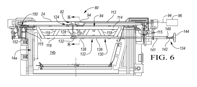
[0017] FIGURE 6 is a sectional view taken along the direction of line 6-6
in Figure 4 to
further illustrate the construction of the location sensing assembly that
supports the fluid switch for
actuating the glass sheet forming cycle.
[0018] FIGURE 7 is an enlarged view of a lateral central portion of the
location sensing
assembly of Figure 6 where the fluid switch is located.
[0019] FIGURE 8 is a sectional view taken generally along the direction of
line 8-8 in Figure
7 to show a carriage and a lock of a lateral positioner that selectively moves
the carriage for lateral
positioning of the fluid switch with respect to the direction of conveyance.
4
CA 03003403 2018-04-26
WO 2017/078659 PCT/US2015/058548
[0020] FIGURE 9 is an enlarged sectional view through the fluid switch
taken in the
opposite direction as Figure 8 and shown as a conveyed glass sheet approaches
the fluid switch to be
sensed in preparation for the forming cycle.
[0021] FIGURE 10 illustrates the fluid switch after having been actuated by
the conveyed
glass sheet.
[0022] FIGURE 11 is an elevational view taken along the direction of Figure
11-11 in Figure
3 to illustrate a positive drive mechanism that drives a roller conveyor on
which the glass sheets are
heated and conveyed into the forming station.
[0023] FIGURE 12 is an enlarged view of a portion of Figure 11 shown as a
toothed belt and
a toothed gear that provide the positive driving of the roller conveyor.
DETAILED DESCRIPTION
[0024] As required, detailed embodiments of the present invention are
disclosed herein;
however, it is to be understood that the disclosed embodiments are merely
exemplary of the
invention that may be embodied in various and alternative forms. The figures
are not necessarily to
scale; some features may be exaggerated or minimized to show details of
particular components.
Therefore, specific structural and functional details disclosed herein are not
to be interpreted as
limiting, but merely as a representative basis for teaching one skilled in the
art to variously employ
the present invention.
[0025] With reference to Figures 1-3, a glass sheet forming system
generally indicated by 10
embodies the present invention and includes a heating furnace 12, a forming
station 14 including
first and second forming locations 16 and 18, and a cooling station 20 for
cooling a formed glass
sheet G by slow cooling for annealing, faster cooling for heat strengthening
or more rapid cooling
for tempering. The furnace and forming station 14 collectively include a
housing identified by 14a
in Figures 3, 3A and 3B and defining a heated chamber 14b. Furthermore, the
furnace 12 and the
first forming section 16 of the forming station 14 include a roller conveyor
22 having conveyor
rollers 24 for conveying a glass sheet G along a direction of conveyance C for
heating. The rollers
24 are made of sintered bonded fused silica particles so as to have resistance
to thermal warpage
CA 03003403 2018-04-26
WO 2017/078659 PCT/US2015/058548
during heating and cooling and thus providing planarity of the glass sheet
during the conveyance.
All of the components of the forming system 10 are controlled by a controller
25 through a control
bundle 25a of wires, optical fibers, tubes, etc. as schematically shown in
Figure 2.
[0026] As shown in Figure 3, each roller 24 has one end 26 that can extend
outwardly of the
furnace to be rotatively driven by a schematically illustrated positive drive
mechanism 28, that is one
that does not solely depend on friction to provide the rotational roller
driving, while another end 30
of each roller is located at a heated location adjacent the junction 32
between the first and second
sections 16 and 18 of the forming station 14 and are received by a roller
support structure 34
schematically illustrated in Figure 3. More specifically, the support
structure 34 as illustrated in
Figures 4 and 5 has an elongated shape along the direction of conveyance C and
includes an
elongated cooling unit including a housing defining a cooling chamber that
receives and has bearings
that rotatably support the aligned set of roller ends 30. The cooling unit as
shown in Figure 5
includes an inlet 44 and an outlet 46 through which cooling fluid is supplied
to the cooling chamber
to provide cooling of the aligned set of roller ends 30 and cooling of the
bearings during operation of
the system.
[0027] In the specific forming system 10 as illustrated in Figure 3,
forming of the glass sheet
is performed with the conveyor roll ends 30 cooled within the support
structure 34. More
specifically, this system has the forming station 14 with its first forming
section 16 having a first
upper mold 48 including a downwardly facing forming face 50 that is curved
along the direction of
conveyance C but has straight line elements transverse to the direction of
conveyance, and the
second forming section 18 has a second upper mold 52 that has a downwardly
facing forming face
54 that is curved both along and transverse to the direction of conveyance C.
Actuators 55 have
rollers 55a that support beams 56 (only one shown) on which the first upper
mold 48 is supported
and moved vertically a slight extent by operation of the actuators 55 during
the forming operation,
and an actuator 57 moves the beams 56 and the first upper mold 48 on the beams
horizontally
between the first and second forming sections 16 and 18 of the forming station
14 during the
forming operation. Lateral rollers 55b also contact the beams 56 to provide
lateral positioning
during movement of the first upper mold 38 between its pickup position in
Figure 3 and its delivery
position in Figure 3a.
6
CA 03003403 2018-04-26
WO 2017/078659 PCT/US2015/058548
[0028] Furthermore, an actuator 58 moves the second upper mold 52
vertically during the
forming cycle of the forming station 14 and a source of pressurized air 60
supplies pressurized air to
first and second gas pumps 61 and 62 to provide a vacuum and at other times
pressurized air through
arrays of holes in the forming faces 50 and 54 of the first and second upper
molds 48 and 52 to
initially support and subsequently release glass sheets G being formed. Also,
a lower mold 64 in the
second forming section 14 of the forming station is supported for vertical
movement by jacks 66
during the forming. This vertical movement can be downward to allow the first
upper mold 38 to
move over the lower mold 64 and then upward so the release of the glass sheet
is at a more closely
spaced relationship to the lower mold to control positioning. In addition, the
vertical movement of
the lower mold 64 can also be used in cooperation with the vertical movement
of the second upper
mold 52 to perform press bending. Also, transfer apparatus 69 identified in
Figure 3 includes a
pressurized air supply having a gas jet pump array 70 that provides lifting of
a heated glass sheet G
from the roller conveyor 22 to the first upper mold 48 and also includes a
vacuum source 72
provided by the pressurized air supply and gas jet pump 61 that selectively
provide the vacuum at
the forming face 50 of upper mold 48 to commence the forming cycle as is
hereinafter described.
[0029] In addition to the forming station 14, the system 10 as shown in
Figure 3 includes a
cooling station 20 to which a formed glass sheet G is moved on a delivery mold
74 by an actuator 76
from the second forming section 18 to the cooling station between lower and
upper quench heads 78
for cooling. As also previously mentioned, this cooling can be slow cooling
for annealing, more
rapid cooling for heat strengthening, or rapid cooling for tempering.
[0030] The forming station 14 illustrated in Figures 3, 3a and 3b has three
stages of operation
wherein the glass sheet is formed on the first upper mold 48 with curvature in
a first direction and
straight line elements in a second direction transverse to the first
direction, by gravity in transverse
directions on the lower mold 64, which has an open center ring shape, after
receipt thereby from the
first upper mold 48 in its delivery position shown in Figure 3a, and finally
by the press forming
between the second upper mold 52 and the lower mold 64 as shown in Figure 3b.
[0031] A cycle of operation of the forming station 14 with reference to
Figure 3 begins by
downward movement of the first upper mold 48 within the left first forming
section 16 so that a
glass sheet G can be lifted off of the roller conveyor 22 by vacuum applied to
the face 50 of the first
7
upper mold 48 and upward gas flow from the gas jet pump array 70. More
specifically, the
first upper mold 48 can be moved downwardly by actuators 55 to about one half
inch (12 to
15 mm) from the conveyor 22 for the initial pickup of the glass sheet and can
then be moved
upwardly so the first upper mold can move above support structure 34. The
actuator 57 then
moves the beams 56 and the first upper mold 48 to the right into the second
forming section
18 of the forming station to the location shown in Figure 3a above the lower
mold 64 and
below the raised upper mold 52 that is shown above the delivery mold 74 that
is then still
operating in the prior cycle. The positioning of the first upper mold 48 and
delivery mold 74
at different elevations within the second forming section 18 at the same time
provides
overlapping cycles that reduces the system cycle time and thus provides
greater output that
advantageously reduces the cost of the final formed glass sheet product.
[0032] After the lower mold 64 receives the glass sheet, the first upper mold
48 moves back
to the first forming section 16 as shown in Figure 3 in preparation for the
next cycle and the
glass sheet G is press formed between the second upper mold 52 and the lower
mold 64 as
shown in Figure 3b. Subsequently the second upper mold 52 is moved upwardly to
the
position of Figure 3a with the press formed glass sheet supported thereby and
the delivery
mold 74 is moved into the second forming section 14 as shown to receive the
press formed
glass sheet for subsequent movement to the quench 20 shown in Figure 3.
[0033] It should be appreciated that the forming station 14 may have other
constructions.
For example, the forming station may alternatively have a first upper mold
that only moves
vertically and a lower mold that moves horizontally from below the first upper
mold to below
a second upper mold at an elevation below the elevation of a delivery mold
that delivers the
formed glass sheet after press forming between the lower mold and the second
upper mold
as disclosed by United States Patent Application Publication No. U.S.
2015/0218029 A11 for
example.
[0034] As illustrated in Figures 4 and 6-8, the glass sheet forming system 10
includes a
glass location sensing assembly 80 having a fluid switch 82 whose construction
is more
specifically illustrated in Figures 9 and 10. This fluid switch 82 is actuated
by the conveyed
glass sheet to provide a glass position control signal that in coordination
with the
conveyance of the glass sheet subsequently actuates the previously described
transfer
apparatus 69 to transfer the glass sheet from
8
CA 3003403 2019-11-29
CA 03003403 2018-04-26
WO 2017/078659 PCT/US2015/058548
the roller conveyor 24 shown in Figure 3 to the forming face 50 of the first
upper mold 48. As
shown in Figure 4, the fluid switch 82 is located at an upstream location of
the forming station 14
where the initial actuation by the conveyed glass sheet takes place upstream
from the location at
which the glass sheet is transferred to the first upper mold 48 shown in
Figure 3. The positive drive
mechanism of the roller conveyor 22 and coordination of its rotational driving
by the controller 25
insures that the transfer takes place at the proper location as is hereinafter
more fully described. That
transfer as was previously described is by the transfer apparatus 69 including
the pressurized air
supply having the gas jet pump array 70 and the vacuum source 72 that provides
the vacuum at the
forming face 50 for the forming.
[0035] As is hereinafter more fully described, the location sensing
assembly 80 includes a
frame 84 mounted on the housing 14a within the heated chamber 14b, and the
frame mounts the
fluid switch 82 as shown in Figures 6-8. The structure of the frame and its
mounting of the fluid
switch 82 as well as the fluid switch operation will be hereinafter more fully
described after an initial
description of the fluid switch.
[0036] As illustrated in Figure 9, the fluid switch 82 includes a housing
collectively indicated
by 86 and a valve member 88 mounted by a pivotal connection 90 on the housing
and shown in a
closed position. The housing 86 has a vacuum chamber 92 in which a vacuum is
drawn through a
vacuum conduit 94 shown in Figures 6 and 7 from a vacuum source 96 shown only
in Figure 6. This
vacuum maintains the valve member 88 in its closed position by isolating the
vacuum chamber 92
from an atmospheric port 98. Vacuum chamber 92 is communicated with a vacuum
sensing port
100 which is communicated by a conduit 102 with a fluid transducer 104 that is
located outside of
the system heated chamber and that is operable to convert a fluid pressure
change to an electrical
control signal for communication to the system controller 25 shown in Figure
2.
[0037] When a glass sheet G is conveyed as shown in Figure 9 to the left
along the direction
of conveyance shown by arrow C, the leading edge extremity 106 of the glass
sheet contacts an
actuating portion 108 of the valve member 88 to initiate counterclockwise
rotation about its pivotal
connection 90 on the housing 86. The initial counterclockwise rotation of the
valve member 88
begins communication of the atmospheric port 98 with the vacuum chamber 92 but
there is then still
a partial vacuum acting clockwise on the valve member 88 inhibiting its
rotation toward the fully
9
CA 03003403 2018-04-26
WO 2017/078659 PCT/US2015/058548
open position shown in Figure 10. However, there is some momentum in the
counterclockwise
pivoting of valve member 88 due to the impact of the glass G and due to
gravity acting on the greater
mass of the valve member 88 to the left of the pivotal connection 90. Also,
the continued
conveyance of the glass to the left will continue to rotate valve member 88 to
the fully open position
of Figure 10 as the vacuum port 100 increases in pressure and through the
conduit 102 provides a
fluid control signal to the transducer 104 which then generates an electrical
control signal that is sent
to the controller 25 (Figure 2) which in coordination with the glass sheet
conveyance subsequently
initiates the upward glass sheet transfer operation previously described. The
housing 86 of the fluid
switch 82 as shown in Figure 10 also includes a pressure port 110 which under
the control of a valve
operated by the controller 25 selectively provides pressurized air from a
pressurized air source
through a conduit 112 to the opposite side of the valve member 88 from the
vacuum chamber 92.
After the glass sheet is transferred upwardly from the conveyor, a burst of
pressurized air fed to the
port 110 pivots the valve member 88 clockwise from the open position of Figure
10 back to the
closed position of Figure 9 in preparation for the next cycle.
[0038] With reference to Figures 6-8, the housing mounted frame 84 of the
location sensing
assembly 80 includes a pair of upper frame members 114 that extend laterally
between opposite
lateral sides 115 of the system housing 14a and are spaced from each other
along the direction of
conveyance as specifically illustrated in Figure 8. Frame 84 also includes a
pair of lower frame
members 116 extending laterally with respect to each other and spaced along
the direction of
conveyance as also shown in Figure 8 as well as being supported by lower ends
of inclined supports
118 whose upper ends are supported by the upper frame members 114. Horizontal
connection frame
members 120 provide connection between the upstream and downstream frame
members. A pair of
support rods 122 (Figure 8) of the frame extend laterally with respect to the
direction of conveyance
spaced along that direction as shown in Figure 8.
[0039] A carriage 124 supports the fluid switch 82 as best shown in Figures
7 and 8 and has
rollers 126 mounted by the support rods 122 for lateral movement with respect
to the direction of
conveyance. The carriage 124 includes a vertically extending carriage member
128 that extends
over and down from the upstream upper frame member 114 to adjacent the
upstream lower frame
member 116.
CA 03003403 2018-04-26
WO 2017/078659 PCT/US2015/058548
[0040] As shown in Figure 6, the location sensing assembly 80 includes a
lateral positioner
130 having an inner connection 132 to the carriage 124 at the lower end of its
vertical member 128
and has an outer operating portion 134 located outside of the system housing
for operation to move
the carriage laterally with respect to the direction of conveyance to
laterally align the fluid switch 82
with the leading extremity of the conveyed glass sheet for the actuation that
provides the glass
position sensing signal for providing glass sheet positioning during the
forming as previously
described. The lateral positioner 130 includes a shaft 136 having an inner end
138 rotatably
supported and axially located by a journal 140 that embodies the inner
connection 132 and is
mounted on the lower end of the vertically extending carriage member 128. The
shaft 136 extends
through a tube 141 mounted on one side wall 115 of the housing and has an
outer end 142 including
a handle 144 for moving the carriage 124 and the fluid switch 82 thereon
laterally with respect to the
direction of conveyance by push/pull movement into alignment with the leading
extremity of the
glass sheet.
[0041] The inner end 138 of the shaft 136 has a lock 146 (Figure 7)
including an eccentric
148 (Figure 8) for locking the carriage 124 to prevent lateral movement with
respect to the direction
of conveyance after the fluid switch 82 is laterally aligned with the leading
extremity of the glass
sheet. The handle 144 is operable to rotate the shaft 138 to lock the
eccentric 148 against the frame
84 at its adjacent lower frame member 116 to prevent carriage movement
laterally with respect to the
direction of conveyance. Rotation of the shaft counterclockwise as shown in
Figure 8 moves the
eccentric 148 out of the contact with the adjacent lower frame member to
prevent the lateral
movement of the carriage for the adjustment. A screw 149 on the tube 140 is
selectively operable to
stop the shaft rotation to lock the carriage after its lateral positioning or
to permit the shaft rotation to
unlock the shaft to permit its lateral positioning.
[0042] As shown in Figure 6, a vertical adjuster 150 includes a wedge 152
for vertically
adjusting one lateral end of the frame 84 to vertically position the fluid
switch 82 with respect to the
horizontal plane along which the glass sheet is conveyed. This adjustment is
only a relatively small
amount to insure that the fluid switch is in an operable vertical position.
[0043] With reference to Figure 11, the positive drive mechanism 28 of the
roller conveyor
22 includes a continuous drive belt 152 having teeth 154 that mesh with teeth
156 with the roller
11
,
,
ends 26 to provide positive driving that does not depend solely upon friction
so that the
actuation of the glass sheet transfer from the conveyor after a time interval
of conveyance
subsequent to the sensing of the glass position while still providing actuate
location. In
addition to meshing with the roller ends 26 and being tooth driven by a
toothed input
sprocket 158, the untoothed side 160 of the drive belt 152 winds around idler
rollers 160 and
an adjustable tensioning roller 162.
[0044] For a more specific disclosure of the roller support structure 34 and
its cooling unit,
see the United States Patent Application Publication US 2017/0121212 that was
filed
concurrently herewith and has the title GLASS SHEET PROCESSING SYSTEM HAVING
COOLING OF CONVEYOR ROLLER ENDS.
[0045] Likewise, for a more specific disclosure of the transfer apparatus 69,
see the United
States Patent Application Publication US 2017/0121213 that also was filed
concurrently
herewith and has the title LIFT DEVICE FOR A GLASS PROCESSING SYSTEM.
[0046] While exemplary embodiments are described above, it is not intended
that these
embodiments describe all possible forms of the invention. Rather, the words
used in the
specification are words of description rather than limitation, and it is
understood that various
changes may be made without departing from the spirit and scope of the
invention.
Additionally, the features of various implementing embodiments may be combined
to form
further embodiments of the invention.
12
CA 3003403 2019-12-06