Note: Descriptions are shown in the official language in which they were submitted.
LIFT DEVICE FOR A GLASS PROCESSING SYSTEM
TECHNICAL FIELD
[0001] The present disclosure relates to a lift device for lifting a glass
sheet in a glass
processing system.
BACKGROUND
[0002] Prior apparatuses for lifting glass sheets are disclosed in by U.S.
Patent Nos.
4,204,854 and 4,356,018, for example.
SUMMARY
[0003] According to one aspect of the present disclosure, an object is to
provide a lift device
for lifting a glass sheet in a glass processing system that includes a
conveyor system having
a plurality of rollers for conveying the glass sheet, the lift device
comprising:
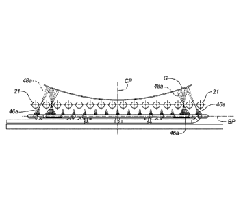
a lift jet array including peripheral lift jet outlets and inner lift jet
outlets disposed inwardly
of the peripheral lift jet outlets, the peripheral lift jet outlets and the
inner lift jet outlets being
disposed below the rollers when the lift device is used with the glass
processing system, and
each lift jet outlet being operable to allow gas to flow toward the glass
sheet; and
a control unit for controlling operation of the lift jet outlets, the control
unit being
configured to commence operation of at least one of the inner lift jet outlets
prior to
commencing operation of at least one of the peripheral lift jet outlets.
[0003a] According to another aspect of the present disclosure, an object is to
provide a lift
device for lifting a glass sheet in a glass processing system that includes a
conveyor system
having a plurality of rollers for conveying the glass sheet, the lifting
device comprising:
a lift jet array including multiple peripheral lift jet outlets and multiple
inner lift jet outlets
disposed inwardly of the peripheral lift jet outlets, wherein at least one
peripheral lift jet outlet
is angled toward a central plane of the lift jet array, and at least one inner
lift jet outlet proximate
the at least one peripheral lift jet outlet is angled away from the central
plane, and wherein the
peripheral lift jet outlets and the inner lift jet outlets are disposed below
the rollers when the
lift device is used with the glass processing system.
1
Date recue/Date received 2023-02-24
[0003b] According to yet another aspect of the present disclosure, there is
also provided a
glass processing system comprising:
a glass sheet bending station including a conveyor system having multiple
conveyor
rollers for conveying a heated glass sheet, and a lift device (such as the one
descried and/or
illustrated in the present patent specification) positioned beneath the
conveyor rollers for lifting
the glass sheet off of the conveyor rollers.
[0003c] According to yet another aspect of the present disclosure, an object
is to provide a
method of lifting a glass sheet off of conveyor rollers in a glass processing
system, the method
comprising:
positioning the glass sheet above a lift jet array including multiple
peripheral lift jet outlets
and multiple inner lift jet outlets disposed inwardly of the peripheral lift
jet outlets, wherein the
peripheral lift jet outlets and the inner lift jet outlets are disposed below
the conveyor rollers;
commencing operation of at least one of the inner lift jet outlets such that
gas flows from
the at least one inner lift jet outlet toward the glass sheet; and
commencing operation of at least one of the peripheral lift jet outlets such
that gas flows
from the at least one peripheral lift jet outlet toward a peripheral portion
of the glass sheet;
wherein the lift jet outlets are operable to facilitate lifting of the glass
sheet toward a tool,
and wherein commencing operation of the at least one peripheral lift jet
outlet is performed
subsequent to commencing operation of the at least one inner lift jet outlet
to inhibit gas from
flowing between the glass sheet and the tool.
[0003d] Other possible aspect(s), object(s), embodiment(s), variant(s) and/or
advantage(s) of
the present disclosure, all being preferred and/or optional, are briefly
summarized
hereinbelow.
[0003e] For example a lift device, according to the disclosure, for lifting a
glass sheet in a
glass processing system includes a lift jet array having peripheral lift jet
outlets and inner lift
jet outlets disposed inwardly of the peripheral lift jet outlets. Furthermore,
each lift jet outlet is
operable to allow gas to flow toward the glass sheet. The lift device also
includes a control
unit for controlling operation of the lift jet outlets, and the control unit
is configured to
la
Date recue/Date received 2023-02-24
commence operation of at least one of the inner lift jet outlets prior to
commencing operation
of at least one of the peripheral lift jet outlets.
[0004] According to another aspect of the disclosure, a lift device for
lifting a glass sheet in a
.. glass processing system includes a lift jet array having multiple
peripheral lift jet outlets and
multiple inner lift jet outlets disposed inwardly of the peripheral lift jet
outlets. At least one
peripheral lift jet outlet is angled toward a central plane of the lift jet
array, and at least one
inner lift jet outlet proximate the at least one peripheral lift jet is angled
away from the central
plane.
[0005] A method according to the disclosure of lifting a glass sheet in a
glass processing
system includes positioning the glass sheet above a lift jet array including
multiple peripheral
lift jet outlets and multiple inner lift jet outlets disposed inwardly of the
peripheral lift jet outlets.
The method further includes commencing operation of at least one of the inner
lift jet outlets
such that gas flows from the at least one inner lift jet outlet toward the
glass sheet, and
commencing operation
lb
Date recite/Date received 2023-02-24
CA 03003423 2018-04-26
WO 2017/078934 PCT/US2016/057683
of at least one of the peripheral lift jet outlets such that gas flows from
the at least one peripheral lift
jet outlet toward a peripheral portion of the glass sheet. The lift jet
outlets are operable to facilitate
lifting of the glass sheet toward a tool, and commencing operation of the at
least one peripheral lift
jet outlet is performed subsequent to commencing operation of the at least one
inner lift jet outlet to
inhibit gas from flowing between the glass sheet and the tool.
[0006] While exemplary embodiments are illustrated and disclosed, such
disclosure should
not be construed to limit the claims. It is anticipated that various
modifications and alternative
designs may be made without departing from the scope of the disclosure.
BRTFF DESCRIPTION OF THE DRAWINGS
[0007] FIGURE 1 is a schematic elevational view of a glass sheet
processing system
including a forming station having a lifting device according to the
disclosure for lifting a heated
glass sheet;
[0008] FIGURE 2 is a sectional view taken through the forming station
along the direction of
line 2-2 in Figure 1 and illustrates a forming apparatus that includes first
and second upper molds, a
lower mold and a delivery mold for performing three stage forming of a hot
glass sheet with
transverse curvature and its subsequent delivery;
[0009] FIGURE 3 is a perspective view of the first upper mold with its
normally
downwardly forming convex surface shown facing generally upwardly for purposes
of illustration;
[0010] FIGURE 4 is a perspective view of the second upper mold with its
normally
downwardly forming convex surface also shown facing generally upwardly for
purposes of
illustration;
[0011] FIGURE 5 is a perspective view of the lower mold which receives
the initially
formed glass sheet from the first upper mold for gravity sagging and movement
to below the second
upper mold for subsequent press foil -fling;
2
CA 03003423 2018-04-26
WO 2017/078934 PCT/US2016/057683
[0012] FIGURE 6 is a view taken along the direction of line 6-6 of Figure
2 to show the
initial pickup of the hot glass sheet from a conveyor system by the first
upper mold for the initial
forming;
[0013] FIGURE 7 is an elevational view taken in the same direction as
Figure 2 and
illustrates the movement of the glass sheet on the lower mold from the first
upper mold to below the
second upper mold for the press forming with transverse curvature;
[0014] FIGURE 8 is an elevational view taken in the same direction as
Figure 7 and
illustrates the operation of the delivery mold for delivering the formed glass
sheet from the forming
station;
[0015] FIGURE 9 is a plan view taken along the direction of line 9-9 in
Figure 6 to illustrate
the lift device including a gas lift jet array that operates to perform the
initial pickup of the glass
sheet from the conveyor system by the first upper mold;
[0016] FIGURE 10 is a perspective view of the lift device for lifting the
glass sheet from a
generally flat condition on the conveyor system to a raised and bent
condition, shown in phantom
lines (the conveyor system is not shown for clarity purposes);
[0017] FIGURE 11 is a side view of the lift device and conveyor system,
showing the glass
sheet in the raised and bent condition;
[0018] FIGURE 12 is an enlarged side view of a portion of the lift device
shown in FIGURE
11;
[0019] FIGURE 13 is a flow chart that illustrates the three stage hot
glass sheet forming
operation;
[0020] FIGURE 14 is a view taken in the same direction as Figure 2 but
illustrating another
embodiment of a three stage fol ming station including a lift device
according to the disclosure;
[0021] FIGURES 15 and 16 are partial views of the forming station of
Figure 14 illustrating
glass sheet processing during a cycle of operation of the system; and
3
CA 03003423 2018-04-26
WO 2017/078934 PCT/US2016/057683
[0022] FIGURE 17 is a flow chart that illustrates the three stage hot
glass sheet forming
operation of the forming station embodiment of Figures 14-16.
DETAILED DESCRIPTION
[0023] As required, detailed embodiments are disclosed herein; however,
it is to be
understood that the disclosed embodiments are merely exemplary and that
various and alternative
forms are possible. The figures are not necessarily to scale; some features
may be exaggerated or
minimized to show details of particular components. Therefore, specific
structural and functional
details disclosed herein are not to be interpreted as limiting, but merely as
a representative basis for
teaching one skilled in the art to variously employ the present disclosure.
Furthermore, as those of
ordinary skill in the art will understand, various features of the embodiments
illustrated and
described with reference to any one of the Figures may be combined with
features illustrated in one
or more other Figures to produce embodiments that are not explicitly
illustrated or described. In
addition, other embodiments may be practiced without one or more of the
specific features explained
in the following description.
[0024] During manufacture of a glass sheet product, such as a glass
mirror panel for a solar
power collection application, a vehicle windshield, rear window, or any other
suitable product, it
may be desirable to lift a sheet of glass in connection with a forming or
bending operation (e.g., to
raise the glass sheet against a mold tool), or in connection with any other
glass processing operation,
to facilitate processing of the glass sheet. In the present disclosure,
methods and apparatuses are
provided for lifting glass sheets during such operations to improve glass
processing (e.g., so that
tight shape tolerances and/or improved optics may be achieved).
[0025] Referring to Figures 1 and 2, a glass processing system 10 is
shown for processing
glass sheets G. The system 10 includes a heating apparatus or station, such as
a furnace 12, for
heating the glass sheets G; a forming or bending station 14 for forming or
bending each glass sheet
G into a desired shape; and a cooling station, such as an annealing station or
a quench station 16,
configured to cool each glass sheet G. In the embodiment shown in Figures 1
and 2, the system 10
further includes a lift device 18, according to the present disclosure,
positioned in the bending station
14 for lifting glass sheets G during the forming or bending process, as
explained below in detail.
4
[0026] The furnace 12 may have any suitable configuration for heating the
glass sheets G.
For example, the furnace 12 may include any suitable heating elements (not
shown)
positioned above and/or below a conveyor or conveyor system 20, which may be
used to
convey the glass sheets G in a generally horizontally extending orientation
along a plane of
conveyance C through the furnace 12. As a more detailed example, the heating
elements may
include radiant heating elements, such as electric heaters, and/or convective
heating
elements, such as hot gas or hot air distributors. The conveyor system 20 may
be a roller
conveyor type including rollers 21 like those disclosed by United States
Patent Nos. :
3,806,312 McMaster; 3,934,970 McMaster et al., 3,947,242 McMaster et al.; and
3,994,711
McMaster et al., for example.
[0027] Likewise, the bending station 14 may have any suitable configuration
for hot glass
forming or bending each glass sheet G into a particular shape. For example,
the bending
station 14 may have a conveyor or conveyor system 22, which may be a separate
conveyor
system or part of the conveyor system 20, for receiving a heated glass sheet
G; and a glass
sheet forming apparatus or bending apparatus 24, shown schematically in Figure
1, for
forming or bending the glass sheet G. Furthermore, the bending station 14 has
an insulated
housing 25 defining a heated chamber 26 (e.g., heated to a temperature in the
range of 610
to 725 degrees centigrade ( C), or at least 600 C) in which the bending
apparatus 24 is
located. Although rollers 21 of the conveyor system 22 are shown contained
within the housing
in Figure 2, ends of each roller 21 may extend laterally beyond side walls of
the housing
25.
[0028] Referring to Figure 2, the bending apparatus 24 may be configured as a
multiple stage
25 .. bending apparatus for bending a glass sheet G in multiple stages (e.g.,
three stages). In the
embodiment shown in Figure 2, the bending apparatus 24 includes a first upper
mold 27 that
functions during a first stage of the hot glass sheet forming or bending, a
second upper mold
28 that functions during a press forming stage of the hot glass sheet forming,
a lower mold 30
that receives the glass sheet G from the first upper mold 27 for gravity
sagging and moves the
glass sheet G from the first upper mold 27 to the second upper mold 28 and
cooperates with
the second upper mold 28 to provide the press forming, and a delivery mold 32
that receives
the formed glass sheet G from the second upper mold 28 for delivery from the
bending station
14 to the quench station 16.
5
Date recue/Date received 2023-02-24
[0029] With continuing reference to Figure 2, a schematically indicated
actuator 34, such as
one or more cylinders, has one or more connections 36 to the first upper mold
27 to provide
movement thereof between an upper position above the conveyor system 22 and,
as shown
in Figure 6, a lower position adjacent the conveyor system 22 and a conveyed
hot glass sheet
G. The first upper mold 27 has a downwardly facing surface 38 that has a
downwardly convex
shape shown in Figure 6 and illustrated by phantom line 40 in Figure 3. The
mold surface 38
also has straight line elements, such as illustrated by phantom line 42, that
may be provided
by a cylindrical shape or a partial conical shape.
[0030] The lift device 18 in the bending station 14 may be configured as a gas
lift jet array
44 for lifting and bending the heated glass sheet G. Referring to Figures 2
and 6, the lift jet
array 44 is located below the plane of conveyance C of the hot glass sheet G
and includes
multiple, spaced apart lift jet outlets or gas jet outlets 46, such as
nozzles, spouts, or pumps,
that supply upwardly directed gas jets 48 (e.g., jet streams) for lifting the
glass sheet G
upwardly from the conveyor system 22 to initially form and support the glass
sheet against the
downwardly facing surface 38 of the first upper mold 27, which is then moved
upwardly to its
upper position with the glass sheet G supported against its downwardly facing
surface 38, as
shown in Figure 2. The downwardly facing surface 38 of the first upper mold 27
may also have
an array of vacuum holes 49 through which a vacuum may be drawn to assist in
initial lifting
of the glass sheet G and to then support the glass sheet as is hereinafter
described.
[0031] As shown in Figure 6, the lift jet array 44 may be configured such that
gas jets 48 of
the gas jet outlets 46 pass between the conveyor rollers 21. In that regard,
some gas jets 48
may flow generally vertically, while other gas jets 48 may flow at angles with
respect to a
vertical plane. Such a configuration may be particularly advantageous when
spacing between
adjacent conveyor rollers 21 is fixed, or when the conveyor rollers 21 are not
able to be easily
adjusted. Furthermore, each gas jet outlet 46 may be made of any suitable
material, such as
stainless steel or any other suitable metal, and may be of the type disclosed
by U.S. Patent
Nos. 4,204,854 and 4,356,018, for example, such that a primary gas flow
therefrom induces
a secondary gas flow many times the extent of the primary gas flow in order to
provide the
lifting.
6
Date recue/Date received 2023-02-24
CA 03003423 2018-04-26
WO 2017/078934 PCT/US2016/057683
[0032] Referring to Figure 9, the gas jet outlets 46 of the lift device
18 include multiple
peripheral or outer gas jet outlets 46a and multiple inner gas jet outlets 46b
disposed inwardly of the
peripheral gas jet outlets 46a. The peripheral gas jet outlets 46a are
configured to lift and support
peripheral portions of the glass sheet G, and the inner gas jet outlets 46b
are configured to lift and
support peripheral portions of the glass sheet G and/or inner portions of the
glass sheet G (i.e.,
portions of the glass sheet G disposed inwardly of the peripheral portions).
Furthermore, the
peripheral lift jet outlets 46a may define an outline that is different than a
periphery of the glass sheet
G when the glass sheet G is positioned above the lift jet array 44 and not in
a lifted state.
[0033] The gas jet outlets 46 may be provided in one or more controllable
portions or zones.
In the embodiment shown in Figure 9, for example, the gas jet outlets 46 are
divided into five zones,
Z1-Z5, that are separately controllable. For example, the lift device 18 may
include a controller or
control unit 50, a pressurized gas (e.g., air) source 52 (e.g., tank, pump, or
blower) and multiple
controllable valves 54 that are adjustably controllable, such as by the
control unit 50, to provide gas
at a desired pressure to each of multiple supply conduits 56 that supply gas
to the five zones, as
explained below in greater detail. Furthermore, the control unit 50 may
include any suitable
hardware and/or software for controlling operation of the lift device 18
(e.g., for performing the
particular algorithms represented by the functions described herein). For
example, the control unit
50 may include one or more processors in communication with one or more
storage devices or
memory units, which include computer readable program instructions that are
executable by the one
or more processors so that the control unit 50 may control operation of the
gas source 52, valves 54,
etc. The control unit 50 may also, or instead, include one or more application
specific integrated
circuits, programmable gate arrays, programmable logic devices, and/or digital
signal processors.
[0034] Referring to Figures 10-12, one or more (e.g., at least one, two,
three, or four) of the
peripheral gas jet outlets 46a may be positioned outwardly of the glass sheet
G when the glass sheet
G is positioned above the lift jet array 44 in an un-lifted state, and the one
or more peripheral gas jet
outlets 46a may be angled toward a central plane C'P, e.g., vertical central
plane, of the lift jet array
44. For example, one, two, three or four of the peripheral gas jet outlets 46a
may be positioned
outwardly of the glass sheet G and each angled toward the central plane CF at
an angle in the range
of 51 to 89.9 degrees (measured between a central axis 58a of the respective
peripheral gas jet outlet
46a and a base plane BP, e.g., horizontal plane or other plane that is
perpendicular to the central
7
CA 03003423 2018-04-26
WO 2017/078934 PCT/US2016/057683
plane CF, of the lift jet array 44), or more particularly at an angle in the
range of 59.9 to 78.9
degrees, when the glass sheet G is positioned above the lift jet array 44 and
not in a lifted state. In
the embodiment shown in Figure 10, at least five peripheral gas jet outlets
46a are positioned
outwardly of the glass sheet G at each end of the glass sheet G when the glass
sheet G is in an un-
lifted state (see glass sheet G shown in solid lines), and each of those
peripheral gas jet outlets 46a is
angled toward the central plane CP.
[0035] At one or both ends of the lift jet array 44, one or more (e.g. at
least one, two, three,
or four) of the inner gas jet outlets 46b, which are positioned inwardly of
the periphery of the glass
sheet G when the glass sheet G is in the un-lifted state, may be angled away
from the central plane
CP. For example, at each end of the lift jet array 44, one or more of the
inner gas jet outlets 46b,
which are positioned on the same side of the central plane CF as the one or
more peripheral gas jet
outlets 46a that are angled toward the central plane CF or which are each
positioned proximate (e.gõ
within 10 to 23 cm of, or more particularly within 13.2 to 18.8 cm of) one of
the one or more such
peripheral gas jet outlets 46a, may each be angled away from the central plane
CP at an angle in the
range of 51 to 89.9 degrees (measured between a central axis 58b of the
respective inner gas jet
outlet 46b and the base plane BP of the lift jet array 44) or more
particularly at an angle in the range
of 59.9 to 78.9 degrees. In the embodiment shown in Figures 10 and 11, at
least three inner gas jet
outlets 46b at each end of the lift jet array 44 are angled away from the
central plane CP.
[0036] Furthermore, at each end of the lift jet array 44, one or more
other inner gas jet outlets
46b, which are positioned inwardly of the periphery of the glass sheet G when
the glass sheet G is in
the un-lifted state, may be angled toward the central plane CP. For example,
one or more inner gas
jet outlets 46b, which are positioned on the same side of the central plane CF
as the one or more
peripheral gas jet outlets 46a that are angled toward the central plane CF or
which are each
positioned proximate (e.g., within 10 to 23 cm of, or more particularly within
13.2 to 18.8 cm of)
one of the one or more such peripheral gas jet outlets 46a, may each be angled
toward the central
plane CF at an angle in the range of 51 to 89.9 degrees (measured between a
central axis 58b of the
respective inner gas jet outlet 46b and the base plane BP of the lift jet
array 44) ) or more particularly
at an angle in the range of 59.9 to 78.9 degrees.
8
CA 03003423 2018-04-26
WO 2017/078934 PCT/US2016/057683
[0037] With the above configuration, the lift device 18 is operable to
effectively and
efficiently lift a glass sheet G, e.g., off of conveyor system 22 and toward
the first upper mold 27.
Furthermore, the gas jet outlets 46 of the lift jet array 44 may be
sequentially controlled to provide
effective lifting, while inhibiting gas from flowing between the glass sheet G
and the first upper
mold 27. For example, the control unit 50 may be configured to sequentially
commence operation of
the lift jet outlets, such that operation of at least one of the inner lift
jet outlets 46b may be initiated
prior to commencing operation of at least one of the peripheral lift jet
outlets 46a. As a more
detailed example, operation of the gas jet outlets 46 in the first through the
fourth zones Z1-Z4 may
be initiated first to raise glass sheet G off of the conveyor system 22 and
commence bending of the
glass sheet G. After sufficient lifting and/or bending of the glass sheet G,
e.g., after 0.1 to 0.5
seconds, or more particularly after about 0.2 seconds, of operation of the gas
jet outlets 46 of zones
Z1-Z4, operation of the peripheral gas jet outlets 46a of the fifth zone Z5
may be initiated to further
lift and/or bend end portions of the glass sheet G sufficiently toward the
first upper mold 27.
Because the peripheral gas jet outlets 46a of the fifth zone Z5 are disposed
outwardly of the glass
sheet G and are angled toward the central plane CF, gas can be prevented from
flowing between the
glass sheet G and the first upper mold 27 by commencing operation of those gas
jet outlets 46a after
commencing operation of the other gas jet outlets 46.
[0038] Furthermore, because the peripheral gas jet outlets 46a of the
fifth zone Z5 may be
angled toward the central plane CP, the jets 48 emitted therefrom may contact
the glass sheet G at
more desirable angles (e.g., angles in the range of 50 to 90 degrees). As a
result, the peripheral gas
jet outlets 46a of the fifth zone Z5 may provide effective bending and/or
lifting of the glass sheet G
toward the downwardly facing surface 38 of the first upper mold 27. In
addition, as shown in Figure
12, gas jets 48 from different gas outlets 46 may converge at the glass sheet
G, or otherwise
generally contact the same area or portion of the glass sheet G, to facilitate
bending and/or lifting of
the glass sheet G. For example, a gas jet 48a from a peripheral gas outlet 46a
that is angled toward
the central plane CF may converge at the glass sheet G with a gas jet 48b of
an inner gas outlet 46b
that is angled away from the central plane CP.
[0039] Returning to Figure 2, the second upper mold 28 of the bending
station 14 is spaced
horizontally away from the first upper mold 27 within the heated chamber 26 of
the bending station
housing 25, and is movable vertically by an actuator 59 and a connection 60
like the actuator and
9
CA 03003423 2018-04-26
WO 2017/078934 PCT/US2016/057683
connection associated with the first upper mold 27. The vertical movement of
the second upper
mold 28 is between an upper position located above the elevation of the plane
of conveyance C and a
lower position (Figure 7) closer to the elevation of the plane of conveyance
C. The second upper
mold 28 has a downwardly facing surface 62 of a downwardly convex shape with
curvature in
transverse directions without any straight line elements as shown by the
curved phantom lines 64
and 66 in Figure 4. The second upper mold 28 also has an array of vacuum holes
68 in its
downwardly facing surface 62 for forming and supporting the heated glass sheet
G against the
second upper mold 28 during the forming cycle.
[0040] It should also be mentioned that the first and second upper molds
27 and 28 can also
be moved upwardly and downwardly at the same time by a single actuator instead
of separate
actuators.
[0041] As shown in Figure 2, a schematically indicated vacuum source 70
is operable to
provide a vacuum at the downwardly facing surfaces 38 and 62 of the first and
second upper molds
27 and 28. Actually, the source of vacuum can be provided by positive pressure
air supplied to gas
jet pumps 72 and 74 on the first and second upper molds 27 and 28, and the jet
pumps may be of the
type disclosed by U.S. Patent Nos. 4,202,681 and 4,222,763 so as to be capable
of drawing varying
degrees of vacuum, as well as providing positive pressure air for providing
glass sheet release during
the forming operation as is hereinafter more fully described.
[0042] The lower mold 30 as best illustrated in Figure 5 faces upwardly
with an upwardly
concave shape in transverse directions complementary to the downwardly convex
shape of the
downwardly facing surface 62 of the second upper mold 28. This lower mold 30
is movable by an
actuator 76 and connection 78 horizontally within the heated chamber 26 of the
bending station
housing 25 to a location below the first upper mold 27 when the first upper
mold 27 is in its upper
position, as shown in Figure 7, with the glass sheet G supported against its
downwardly facing
surface 38. The first upper mold 27 is then movable downwardly to release the
glass sheet for
transfer onto the lower mold 30. The release of the glass sheet G can be
provided by the termination
of the vacuum drawn and the termination of the upwardly directed gas jets
provided by the gas jet
array 44 previously described, as well as by providing positive pressure gas
to the mold surface 38.
The first upper mold 27 is then moved upwardly to its upper position and the
lower mold 30 and the
CA 03003423 2018-04-26
WO 2017/078934 PCT/US2016/057683
glass sheet G supported thereon are moved horizontally to a location below the
second upper mold
28 while in its upper position as shown in Figure 2. During this movement, the
glass sheet G sags by
gravity toward the shape of the lower mold 30 with curvature in transverse
directions. The second
upper mold 28 is then moved downwardly from its upper position shown in Figure
2 to its lower
position shown in Figure 7 to cooperate with the lower mold 30 to press form
the glass sheet G with
curvature in transverse directions, and the second upper mold 28 then has a
vacuum drawn at its
downwardly facing surface 62 to support the glass sheet and is moved upwardly
to its upper position
shown in Figure 8.
[0043] The glass forming operation continues by the lower mold 30 being
moved out from
under the second upper mold 28 and back under the first upper mold 27 as shown
by phantom line
representation in Figure 7, while the delivery mold 32 is moved from its
Figure 2 position at the
quench station 16 to a location below the second upper mold 28 to receive the
glass sheet, as shown
in Figure 8, as the vacuum is terminated at the second upper mold 28 so the
glass sheet G drops onto
the delivery mold 32. The delivery mold 32 is then moved by its actuator 80
and connection 82 out
of the bending station 14 for delivery or further processing of the pressed
formed glass sheet, such as
by quenching in the quench station 16 between lower and upper quench heads 84
and 86, as shown
in Figure 2.
[0044] The system 10 may further include a controller or control unit 88,
shown in Figure 1,
for controlling operation of the above components. The control unit 88 may
have a bundle of
connections 90 for connecting with the various components of the system 10,
such as the conveyor
system 20, the conveyor system 22, the first upper mold 27, the second upper
mold 28, the lower
mold 30, the delivery mold 32, the lift device 18, the vacuum source 70 and
the quench station 16.
Furthermore, the control unit 88 may include any suitable hardware and/or
software for controlling
operation of the above components in order to perform the press forming of the
glass sheet G, as
well as its delivery and quenching (e.g., for performing the particular
algorithms represented by the
functions described herein). For example, the control unit 88 may include one
or more processors in
communication with one or more storage devices or memory units, which include
computer readable
program instructions that are executable by the one or more processors so that
the control unit 88
may control operation of the conveyor system 20, the conveyor system 22, the
first upper mold 27,
the second upper mold 28, the lower mold 30, the delivery mold 32, the lift
device 18, the vacuum
11
CA 03003423 2018-04-26
WO 2017/078934 PCT/US2016/057683
source 70, the quench station 16, etc. The control unit 88 may also, or
instead, include one or more
application specific integrated circuits, programmable gate arrays,
programmable logic devices,
and/or digital signal processors. In lieu of the connections 90, the control
unit 88 may instead be
connected wirelessly to one or more of the above components. Furthermore, the
control unit 50 of
the lift device 18 may be part of the control unit 88, or the control unit 50
may be separate from the
control unit 88 but configured to communicate with the control unit 88.
[0045] In the three stage bending station disclosed, the vacuum source 70
shown in Figure 2
is operated by the control unit 88 shown in Figure 1 to provide a vacuum to
the downwardly facing
surface 38 of the first upper mold 27 in order to cooperate with the lift
device 18 in lifting the glass
sheet G from the roll conveyor 22 into contact with the first upper mold 27 at
its downwardly facing
surface 38 for initially forming and support of the glass sheet G. After the
glass sheet G is moved
upwardly and contacts the downwardly facing surface 38 of the first upper mold
27, the control unit
88 may terminate the operation of the gas lift jet array 44 while continuing
to provide the vacuum
that is then the sole support of the glass sheet G on the first upper mold 27.
[0046] Returning to Figure 9, additional aspects of the lift device 18
will now be described in
more detail. The gas jet outlets 46 of the first and second zones Z1 and Z2,
respectively, are
configured to provide lifting of central portions of the glass sheet G, the
gas jet outlets 46 of the third
and fourth zones Z3 and Z4 are configured to provide lifting of intermediate
and end portions of the
glass sheet G, and the gas jet outlets 46 of the fifth zone Z5, which extend
beyond the opposite end
portions of the glass sheet G, are configured to provide lifting of the end
portions of the glass sheet
G. In another embodiment, the gas jet outlets 46 at opposite ends of the gas
jet array 44 may be
provided in separate zones. Furthermore, as mentioned above, operation of the
gas jet outlets 46 of
zones Z1 through Z5 may be initiated sequentially. For example, the control
unit 50 or the control
unit 88 may control operation of the gas source 52 and valves 54 such that
valves 54a-54d are
opened first to provide heated and pressurized gas (e.g., air) through
conduits 56a-56d and to the gas
jet outlets 46 of the first through fourth zones Z1-Z4 to commence lifting and
bending of the glass
sheet G. Pressurized gas from the gas source 52 may be heated during its flow
into and through a
heated path in the heated chamber 26 of the bending station 14. After
sufficient lifting and/or
bending of the glass sheet G, such as against the first upper mold 27, end
portions of the glass sheet
G are aligned with central axes 58a of the peripheral gas jet outlets 46a of
the fifth zone Z5. The
12
valves 54e may then be opened to provide heated and pressurized gas (e.g.,
air) to the
peripheral gas jet outlets 46a of the fifth zone Z5 so that jet streams 48
emitted from the
peripheral gas jet outlets 46a of the fifth zone Z5 may contact end portions
of the glass sheet
G and cause further bending and/or lifting of the glass sheet G, such as
against the first upper
mold 27. Without such sequential operation, jet streams 48a emitted from the
peripheral gas
jet outlets 46a of the fifth zone Z5 may cause gas to be introduced between
the gas sheet G
and the first upper mold 27, which may inhibit full desired bending of the
glass sheet G and/or
inhibit adequate support against the first upper mold 27 by vaccum drawn at
the first upper
mold surface 38.
[0047] In addition to providing sequential control of the zones Z1-Z5, the
valves 54 may be
adjustably controlled to vary the gas pressure supplied to the conduits 56 and
gas jet outlets
46. As another example, the valves 54 may be configured as on/off valves, and
the lift device
18 may further include a pressure regulator (e.g., programmable electronic
proportional
pressure regulator) upstream of each valve 54 for controlling pressure in each
respective
conduit 56. Of course, the valving and control for supplying the gas jet array
44 can also be
constructed in different ways than the specific way shown to sequentially and
adjustably
control the amount of lifting and support at the central, intermediate and end
portions of the
glass sheet G. Furthermore, this operation takes place after the downward
movement of the
first upper mold 27 to receive the glass sheet G for the first stage of
forming and can then be
terminated while the vacuum continues to be drawn at the first upper mold
surface 38 to
continue the support of the glass sheet G. The vacuum may be continued until
release of the
glass sheet G onto the lower mold 30 and such termination may be accompanied
by supply
of positive pressure air supplied by the gas jet pump 72.
[0048] It is also possible to assist the gas jet outlets 46 with mechanical
pressing of the glass
sheet G against the first upper mold 27 at its downwardly facing surface 38 so
as to ensure
completed glass contact therewith even with abrupt curvature at one or more
locations. For
example, this type of pressing can be performed by having one or more press
members
mounted on the first upper mold 27 and operated by the controller 88 through
one or more
actuators that extend between the first upper mold 27 and the press members,
which may
pivot or otherwise move relative to the first upper mold 27. See U.S. Patent
No. 4,514,208,
which discloses mechanical pressing against an upper mold, for example, and
may be referred
to, if need may be.
13
Date recue/Date received 2023-02-24
CA 03003423 2018-04-26
WO 2017/078934 PCT/US2016/057683
[0049] With reference to the flow chart of Figure 13, processing of the
glass sheet G in the
system 10 begins by heating 100 of the glass sheet (such as to a temperature
in the range of 575 C to
675 C, or to a temperature of at least 575 C) in the furnace and its
subsequent conveyance 102 after
heating into the bending station to begin the press forming or bending
operation. The first upper
mold is then moved downwardly, as illustrated at 104, to receive the glass
sheet for the initial
forming with curvature in the first direction and straight line elements in
the second transverse
direction. As mentioned above, the lift device according to the present
disclosure functions to lift
the glass sheet toward the first upper mold, and the sequential commencement
of operation of inner
gas jet outlets followed by the peripheral gas jet outlets provides improved
lifting and initial bending
of the glass sheet against the first upper mold. Next, the first upper mold
and glass sheet are moved
upwardly 106 and, as shown at 108, the lower mold is subsequently moved under
the raised first
upper mold and the glass sheet is released onto the lower mold for the gravity
sagging that starts the
transverse curvature. The lower mold and initially formed glass sheet are then
moved as shown by
110 to below the second upper mold, which is then moved downwardly as shown by
112 to press
form the initially formed glass sheet with transverse curvature. The second
upper mold is then
moved upwardly as shown at 114 and the lower mold is moved out from below the
second upper
mold, followed by the delivery mold movement 116 below the second upper mold
to receive the
formed glass sheet for delivery. The downward second upper mold movement shown
by 112
initiates the press forming of the glass sheet with the lower mold as vacuum
is supplied to the second
upper mold to provide the press forming in transverse directions with optics
that are enhanced by the
initial forming of the glass sheet with straight line elements followed by the
gravity sagging before
the press forming.
[0050] Referring to Figure 14, another embodiment 14' of a three stage
forming or bending
station is shown with which the lift device 18 according to the present
disclosure may be used. The
forming station 14' is part of a glass processing system 10' that has an
upstream furnace (not shown),
like the glass processing system 10 described above in detail. Furthermore,
the forming station 14'
has many of the same components that operate like those of the previously
described embodiment,
such that like references numerals are applied to like components, except that
the reference numbers
for the components of the forming station 14' may each include a prime mark.
Furthermore, much of
the previous description is applicable to the forming station 14' and thus
will not be repeated.
14
[0051] In the forming station 14' illustrated in Figures 14-16, a heated glass
sheet G on a
conveyor or conveyor system 22' may be lifted off of rolls or rollers 21 'of
the conveyor system
22' by the lift device 18, so that the glass sheet G may be received by first
upper mold 27'. As
mentioned above, the first upper mold 27' may also have an array of vacuum
holes through
which a vacuum may be drawn to assist in initial lifting of the glass sheet G
and to then support
the glass sheet against the first upper mold 27'.
[0052] In the embodiment shown in Figure 14, the rollers 21 of the conveyor
system 22' have
at least one end disposed inside of housing 25'. For example, each roller 2r
has one end 117
that can extend outwardly of the housing 25' to be rotatively driven by a
schematically
illustrated drive mechanism 118, while another end 119 of each roller 21' is
located at a
heated location of the forming station 14' (e.g., within a heated chamber,
defined by housing
25', that is heated to a temperature in the range of 610 C to 725 C) and is
received by a roller
support structure 120 schematically illustrated in Figure 14 (the center
section of the roller 21
shown in Figure 14 is broken away to show jets 48 from the lift device 18).
Furthermore, the
roller support structure 120 may have an elongated shape along the direction
of conveyance
C and include an elongated cooling unit (not shown) having a housing defining
a cooling
chamber that receives and has bearings that rotatably support the aligned set
of roller ends
119. Additional details of the conveyor system 22' are disclosed in U.S.
Application Serial No.
14/929,763 (Attorney Docket No. GLT 1996 PUS), for example, and may be
referred to, if
need may be.
[0053] With the above configuration of the conveyor system 22', spacing
between adjacent
rollers 21' may be fixed or not easily adjusted (e.g., adjacent rollers 21'
may be spaced apart
by 4 inches, center-to-center, and each roller 21' may have a 2 1/2 inch
diameter). As
mentioned above, the gas outlets 46 of the lift device 18 may be configured or
arranged such
that the associated gas jets 48 pass between the rollers 21'. For example,
some of the gas jet
outlets 46 may be oriented generally vertically, and other gas jet outlets 46
may be angled as
mentioned above in detail. Furthermore, the angle of each gas jet outlet 46
may be selected
or designed to account for flow influencing factors (e.g., Bernoulli effect,
Coanda effect, etc.)
that may be experienced when the associated gas jet 48 passes by one or more
rollers 21'.
For example, a particular angle of a gas jet outlet 46 may be increased or
decreased to
account for tendency of the corresponding gas jet 48 to be attracted to one or
both rollers 21'
between which the gas jet 48 passes.
Date recue/Date received 2023-02-24
CA 03003423 2018-04-26
WO 2017/078934 PCT/US2016/057683
[0054] After the glass sheet G is supported against the first upper mold
27 as described
above, the first upper mold 27' is moved horizontally from its pickup position
shown in Figure 14 to
a delivery position shown in Figure 15 where the glass sheet G is released
onto lower mold 30'. This
is different from the prior embodiment where the lower mold 30 provides the
horizontal movement.
After the glass sheet is deposited on the lower mold 30' by the first upper
mold 27', the first upper
mold 27' moves back from its delivery position shown in Figure 15 to its
pickup position shown in
Figure 14 and the second upper mold 28 moves downwardly as shown in Figure 16
to cooperate
with the lower mold in press forming the glass sheet as previously described.
After the press
forming, the second upper mold 28 moves upwardly with the glass sheet
supported against its
downwardly facing surface 62 by a drawn vacuum as previously described and the
delivery mold 32
shown in Figure 14 is moved from the quench station 16 into the forming
station 14' to receive the
glass sheet for movement back out to the quench station between the lower and
upper quench heads
84 and 86 for quenching as also previously described.
[0055] As shown in Figure 14, the first upper mold 27' has a frame 121
that is supported by
elongated beams 122 (only one shown) that are moved by an actuator 123 through
a connection 124.
These beams 122 are supported by associated rollers 126 that are mounted by
actuators 128 to
provide vertical movement of the beams and hence vertical movement of the
first upper mold 27'
during its operation. More specifically, the first upper mold 27' can be moved
downwardly to about
one half inch (12 to 15 mm) from the conveyor system 22' for the initial
pickup of the glass sheet
and can then be moved upwardly so as to move above drive mechanism covers 130
located at the
ends of conveyor rollers 21' to reduce heat flow from the interior of the
forming station to the factory
ambient. Lateral rollers 132 also contact the beams to provide lateral
positioning during movement
of the first upper mold 27' between its pickup position shown in Figure 14 and
its delivery position
shown in Figure 15.
[0056] The forming station 14' illustrated in Figures 14-16 thus also has
three stages of
operation wherein the glass sheet is formed on the first upper mold 27' with
curvature in a first
direction and straight line elements in a second direction transverse to the
first direction, by gravity
on the lower mold 30' after receipt thereby from the first upper mold 27' in
its delivery position
shown in Figure 15, and finally by the press forming between the second upper
mold 28 and the
lower mold 30' as shown in Figure 16.
16
CA 03003423 2018-04-26
WO 2017/078934 PCT/US2016/057683
[0057] The lower mold 30' as illustrated is supported by a framework 134
that is supported
by actuators 136, such as screw jacks, for vertical movement. This vertical
movement can be
downward to allow the first upper mold 27' to move over the lower mold 30' and
then upward so that
the release of the glass sheet is at a more closely spaced relationship to
control positioning. In
addition, the vertical movement of the lower mold 30' can also be used in
cooperation with the
vertical movement of the second upper mold 28 to perform the press bending.
[0058] With reference to the flow chart of Figure 17, the embodiment of
Figures 14-16
performs the press forming operation beginning by heating 138 of the glass
sheet G in the furnace
(such as to a temperature in the range of 575 C to 675 C, or to a temperature
of at least 575 C) and
its subsequent conveyance 140 into the forming station, followed by the first
upper mold receiving
the glass sheet from the conveyor system for initial forming with straight
line elements in the first
stage 142, and then the horizontal movement 144 of the first upper mold and
the glass sheet to above
the lower mold. Then, the glass sheet is released 146 from the first upper
mold onto the lower mold
to provide gravity sagging in the second stage, which can be performed in a
shorter time than when
the lower mold moves horizontally. The second upper mold is then moved
downwardly at 148 to the
lower mold for press forming with transverse curvature in the third stage.
Next, the second upper
mold and glass sheet are moved upwardly at 150, followed by the delivery mold
movement 152
below the second upper mold to receive the press formed glass sheet. The
delivery mold is then
moved out of the forming station for delivery.
[0059] Both embodiments can have reduced cycle time by the vertical
positioning of the
constructions disclosed. In the embodiment of Figures 1-13, the vertical
positioning permits both the
lower mold 30 and the delivery mold 32 to be below the second upper mold 28 at
the same time so
successive cycles overlap to reduce cycle time. In the embodiment of Figures
14-17, the vertical
positioning permits both the first upper mold 27' and the delivery mold 32 to
be below the second
upper mold 28 at the same time so successive cycles overlap to reduce cycle
time.
[0060] Additional details of the above described three stage forming or
bending stations may
be found in U.S. Application Serial No. 14/174,265 (Attorney Docket No. GLT
1964 PUS), which is
hereby incorporated by reference in its entirety. Of course a lift device
according to the present
disclosure may be used with any suitable bending station or glass processing
system. For example, a
17
CA 03003423 2018-04-26
WO 2017/078934 PCT/US2016/057683
lift device according to the present disclosure may be used to lift a glass
sheet toward any suitable
tool (e.g., mold, shuttle, etc.).
[0061] Generally then, a method according to the present disclosure of
lifting a glass sheet in
a glass processing system includes positioning the glass sheet above a lift
jet array including
multiple peripheral lift jet outlets and multiple inner lift jet outlets
disposed inwardly of the
peripheral lift jet outlets. The method further includes commencing operation
of at least one of the
inner lift jet outlets such that gas flows from the at least one inner lift
jet outlet toward the glass
sheet, and commencing operation of at least one of the peripheral lift jet
outlets such that gas flows
from the at least one peripheral lift jet outlet toward a peripheral portion
of the glass sheet. The lift
jet outlets are operable to facilitate lifting of the glass sheet toward a
tool, and wherein commencing
operation of the at least one peripheral lift jet outlet is performed
subsequent to commencing
operation of the at least one inner lift jet outlet to inhibit gas from
flowing between the glass sheet
and the tool.
[0062] While exemplary embodiments are described above, it is not
intended that these
embodiments describe all possible forms according to the disclosure. The words
used in the
specification are words of description rather than limitation, and it is
understood that various
changes may be made without departing from the spirit and scope of the
disclosure. Additionally,
the features of various implementing embodiments may be combined to form
further embodiments
according to the disclosure.
18