Note: Descriptions are shown in the official language in which they were submitted.
A Container For Use With Apparatus
For Heating Smokable Material
Technical Field
The present invention relates to articles for use with apparatus for heating
smokable material to volatilise at least one component of the smokable
material, and to
systems comprising such apparatus and such articles.
Background
Smoking articles such as cigarettes, cigars and the like burn tobacco during
use
to create tobacco smoke. Attempts have been made to provide alternatives to
these
articles by creating products that release compounds without combusting.
Examples of
such products are so-called "heat not burn" products or tobacco heating
devices or
products, which release compounds by heating, but not burning, material. The
material
may be, for example, tobacco or other non-tobacco products, which may or may
not
contain nicotine.
Summary
A first aspect of the present invention provides an article for use with
apparatus
for heating smokable material to volatilise at least one component of the
smokable
material, the article comprising:
a malleable container defining a cavity:
a mass of smokable material in the cavity; and
heating material that is heatable by penetration with a varying magnetic field
to
heat the smokable material.
In an exemplary embodiment, the container comprises a sachet.
In an exemplary embodiment, the container defines an exterior of the article.
CA 3003521 2019-09-24
CA 03003521 2018-04-27
WO 2017/072148 PCT/EP2016/075738
2
In an exemplary embodiment, at least a portion of the container is porous for
permitting volatilised material generated by heating the smokable material
within the
cavity to leave the cavity.
In an exemplary embodiment, the heating material is in the cavity.
In an exemplary embodiment, the heating material is within the mass of
smokable material.
In an exemplary embodiment, the article comprises a material that comprises a
mixture of the smokable material and the heating material.
In an exemplary embodiment, the mixture comprises a mixture of the smokable
material and elements, wherein each of the elements comprises heating material
that is
heatable by penetration with a varying magnetic field.
In an exemplary embodiment, each of the elements comprises a closed circuit of
heating material that is heatable by penetration with a varying magnetic
field.
In an exemplary embodiment, each of the elements consists entirely, or
substantially entirely, of the heating material.
In an exemplary embodiment, the container is free of heating material that is
heatable by penetration with a varying magnetic field to heat the smokable
material.
In an exemplary embodiment, the container comprises the heating material.
In an exemplary embodiment, the article comprises a closed circuit of heating
material that is heatable by penetration with a varying magnetic field.
In an exemplary embodiment, the container comprises a closed circuit of
heating
material that is heatable by penetration with a varying magnetic field.
CA 03003521 2018-04-27
WO 2017/072148 PCT/EP2016/075738
3
In an exemplary embodiment, the container comprises a mesh that comprises
the heating material.
In an exemplary embodiment, the heating material is in contact with the
smokable material.
In an exemplary embodiment, the heating material comprises one or more
materials selected from the group consisting of: an electrically-conductive
material, a
magnetic material, and a magnetic electrically-conductive material.
In an exemplary embodiment, the heating material comprises a metal or a metal
alloy.
In an exemplary embodiment, the heating material comprises one or more
materials selected from the group consisting of: aluminium, gold, iron,
nickel, cobalt,
conductive carbon, graphite, plain-carbon steel, stainless steel, ferri tic
stainless steel,
copper, and bronze.
In an exemplary embodiment, the smokable material comprises tobacco and/or
one Or more humectants.
In an exemplary embodiment, a first portion of the heating material is more
susceptible to eddy currents being induced therein by penetration with a
varying
magnetic field than a second portion of the heating material.
In an exemplary embodiment, the article comprises a catalytic material on at
least a portion of the heating material.
In an exemplary embodiment, an exterior of the article has a length, a width
perpendicular to the length, and a depth perpendicular to each of the length
and the
width, wherein the length is greater than or equal to the width, and wherein
the width is
greater than the depth.
CA 03003521 2018-04-27
WO 2017/072148 PCT/EP2016/075738
4
A second aspect of the present invention provides an article for use with
apparatus for heating smokable material to volatilise at least one component
of the
smokable material, the article comprising:
a container defining a cavity;
a mass of smokable material in the cavity; and
heating material that is heatable by penetration with a varying magnetic field
to
heat the smokable material;
wherein at least a portion of the container is porous for permitting
volatilised
material generated by heating the smokable material within the cavity to leave
the
cavity.
The article of the second aspect may have any one or more of the features
discussed above as being present in respective exemplary embodiments of the
article of
the first aspect of the present invention.
A third aspect of the present invention provides a system, comprising:
apparatus for heating smokable material to volatilise at least one component
of
the smokable material; and
an article for use with the apparatus, the article comprising a container
defining
a cavity, and a mass of smokable material in the cavity;
wherein the apparatus comprises a heating zone for receiving at least a
portion
of the article, and a magnetic field generator for generating a varying
magnetic field to
be used in heating the smokable material when the portion of the article is in
the heating
zone; and
wherein the container is malleable, and/or a portion of the container is
porous
for permitting volatilised material generated by heating the smokable material
within
the cavity to leave the cavity.
In an exemplary embodiment, the apparatus comprises heating material that is
heatable by penetration with the varying magnetic field to heat the smokable
material
when the portion of the article is in the heating zone.
CA 03003521 2018-04-27
WO 2017/072148 PCT/EP2016/075738
In an exemplary embodiment, the article comprises heating material that is
heatable by penetration with the varying magnetic field to heat the smokable
material
when the portion of the article is in the heating zone.
5 In an
exemplary embodiment, the article of the system is the article of the first
aspect of the present invention. The article of the system may have any one or
more of
the features discussed above as being present in respective exemplary
embodiments of
the article of the first aspect of the present invention.
In an exemplary embodiment, the article of the system is the article of the
second
aspect of the present invention. The article of the system may have any one or
more of
the features discussed above as being present in respective exemplary
embodiments of
the article of the second aspect of the present invention.
Brief Description of the Drawings
Embodiments of the invention will now be described, by way of example only,
with reference to the accompanying drawings, in which:
Figure 1 shows a schematic cross-sectional view of an example of an article
for
use with apparatus for heating smokable material to volatilise at least one
component
of the smokable material;
Figure 2 shows a schematic cross-sectional view of an example of another
article
for use with apparatus for heating smokable material to volatilise at least
one component
of the smokable material;
Figure 3 shows a schematic cross-sectional view of an example of another
article
for use with apparatus for heating smokable material to volatilise at least
one component
of the smokable material; and
CA 03003521 2018-04-27
WO 2017/072148 PCT/EP2016/075738
6
Figure 4 shows a schematic cross-sectional view of an example of a system
comprising the article of Figure 1 and apparatus for the heating smokable
material of
the article to volatilise at least one component of the smokable material.
Detailed Description
As used herein, the term "smokable material" includes materials that provide
volatilised components upon heating, typically in the form of vapour or an
aerosol.
"Smokable material" may be a non-tobacco-containing material or a tobacco-
containing
material. "Smokable material" may, for example, include one or more of tobacco
per
se, tobacco derivatives, expanded tobacco, reconstituted tobacco, tobacco
extract,
homogenised tobacco or tobacco substitutes. The smokable material can be in
the form
of ground tobacco, cut rag tobacco, extruded tobacco, reconstituted tobacco,
reconstituted smokable material, liquid, gel, gelled sheet, powder, or
agglomerates, or
the like. "Smokable material" also may include other, non-tobacco, products,
which,
depending on the product, may or may not contain nicotine. "Smokable material"
may
comprise one or more humectants, such as glycerol or propylene glycol.
As used herein, the term "heating material" or "heater material" refers to
material that is heatable by penetration with a varying magnetic field.
As used herein, the terms "flavour'' and "flavourant" refer to materials
which,
where local regulations permit, may be used to create a desired taste or aroma
in a
product for adult consumers. They may include extracts (e.g., liquorice,
hydrangea,
Japanese white bark magnolia leaf, chamomile, fenugreek, clove, menthol,
Japanese
mint, aniseed, cinnamon, herb, wintergreen, cherry, berry, peach, apple,
Drambuie,
bourbon, scotch, whiskey, spearmint, peppermint, lavender, cardamom, celery,
cascarilla, nutmeg, sandalwood, bergamot, geranium, honey essence, rose oil,
vanilla,
lemon oil, orange oil, cassia, caraway, cognac, jasmine, ylang-ylang, sage,
fennel,
piment, ginger, anise, coriander, coffee, or a mint oil from any species of
the genus
Mentha), flavour enhancers, bitterness receptor site blockers, sensorial
receptor site
activators or stimulators, sugars and/or sugar substitutes (e.g., sucralose,
acesulfame
potassium, aspartame, saccharine, cyclamates, lactose, sucrose, glucose,
fructose,
CA 03003521 2018-04-27
WO 2017/072148 PCT/EP2016/075738
7
sorbitol, or mannitol), and other additives such as charcoal, chlorophyll,
minerals,
botanicals, or breath freshening agents. They may be imitation, synthetic or
natural
ingredients or blends thereof. They may be in any suitable form, for example,
oil, liquid,
gel, powder, or the like.
Induction heating is a process in which an electrically-conductive object is
heated by penetrating the object with a varying magnetic field. The process is
described
by Faraday's law of induction and Ohm's law. An induction heater may comprise
an
electromagnet and a device for passing a varying electrical current, such as
an
alternating current, through the electromagnet. When the electromagnet and the
object
to be heated are suitably relatively positioned so that the resultant varying
magnetic
field produced by the electromagnet penetrates the object, one or more eddy
currents
are generated inside the object. The object has a resistance to the flow of
electrical
currents. Therefore, when such eddy currents are generated in the object,
their flow
against the electrical resistance of the object causes the object to be
heated. This process
is called Joule, ohmic, or resistive heating. An object that is capable of
being
inductively heated is known as a susceptor.
It has been found that, when the susceptor is in the form of a closed circuit,
magnetic coupling between the susceptor and the electromagnet in use is
enhanced,
which results in greater or improved Joule heating.
Magnetic hysteresis heating is a process in which an object made of a magnetic
material is heated by penetrating the object with a varying magnetic field. A
magnetic
material can be considered to comprise many atomic-scale magnets, or magnetic
dipoles. When a magnetic field penetrates such material, the magnetic dipoles
align
with the magnetic field. Therefore, when a varying magnetic field, such as an
alternating magnetic field, for example as produced by an electromagnet,
penetrates the
magnetic material, the orientation of the magnetic dipoles changes with the
varying
applied magnetic field. Such magnetic dipole reorientation causes heat to be
generated
in the magnetic material.
CA 03003521 2018-04-27
WO 2017/072148 PCT/EP2016/075738
8
When an object is both electrically-conductive and magnetic, penetrating the
object with a varying magnetic field can cause both Joule heating and magnetic
hysteresis heating in the object. Moreover, the use of magnetic material can
strengthen
the magnetic field, which can intensify the Joule heating.
In each of the above processes, as heat is generated inside the object itself,
rather
than by an external heat source by heat conduction, a rapid temperature rise
in the object
and more uniform heat distribution can be achieved, particularly through
selection of
suitable object material and geometry, and suitable varying magnetic field
magnitude
and orientation relative to the object. Moreover, as induction heating and
magnetic
hysteresis heating do not require a physical connection to be provided between
the
source of the varying magnetic field and the object, design freedom and
control over
the heating profile may be greater, and cost may be lower.
Referring to Figure 1 there is shown a schematic cross-sectional view of an
example of an article according to an embodiment of the invention. The article
1
comprises a malleable container 10 defining a cavity 14, a mass of smokable
material
located in the cavity 14, and heating material that is heatable by penetration
with a
varying magnetic field to heat the smokable material 20. Examples of such
heating
20 material are described below. The article 1 is for use with
apparatus for heating the
smokable material 20 to volatilise at least one component of the smokable
material 20
without burning the smokable material 20, such as the apparatus 100 shown in
Figure 4
and described below.
In this embodiment, the container 10 comprises a sachet 10. In this
embodiment,
the sachet 10 comprises a first wall 11 and a second wall 12, and together the
first and
second walls 11, 12 define the cavity 14. In other embodiments, the sachet 10
may
comprise one wall that defines the cavity 14 or more than two walls that
together define
the cavity 14. In this embodiment, the first and second walls 11, 12 are
separate
components that have been attached to each other to define the sachet 10 and
the cavity
14. More particularly, respective flanges I la, 12a of the first and second
walls 11, 12
are attached to each other. In other embodiments, the first and second walls
11, 12 may
not have flanges as such. Such attachment may be by press-sealing, heat-
sealing,
CA 03003521 2018-04-27
WO 2017/072148 PCT/EP2016/075738
9
welding, sonic welding, use of an adhesive, or the like. In other embodiments,
the first
and second walls 11, 12 may be respective portions of a single component,
which may
for example have been folded. Parts of the two portions may be attached to
each other
to define the sachet 10 and the cavity 14, such as by any of the attachment
methods
discussed above.
In this embodiment, the container 10 is porous for permitting volatilised
material
generated by heating the smokable material 20 within the cavity 14 to leave
the cavity
14. In this embodiment, the container 10 is made of a material that is
impermeable to
the volatilised material but has a plurality of apertures extending
therethrough for
permitting the passage of the volatilised material from the cavity 14 to the
exterior of
the article 1. The container 10 may be, or may comprise, a mesh. In a
variation to this
embodiment, the container 10 may be substantially impermeable to the
volatilised
material and have only one such aperture extending therethrough. In a further
variation
to this embodiment, the container 10 may be made of porous material. Such a
porous
container 10 may or may not have one or more apertures extending therethrough.
The
container 10 may be, for example, made from one or more porous materials
selected
from the group consisting of: fleece, viscose, non-woven material, non-woven
fleece,
woven material, knitted material, nylon, and polyester. In some embodiments,
the
container 10 is configured so as to prevent spilling of the smokable material
20 from
the cavity 14.
In this embodiment, each of the first and second walls 11, 12 is porous for
permitting volatilised material generated by heating the smokable material 20
within
the cavity 14 to leave the cavity 14. In other embodiments, only a portion,
such as one
of the first and second walls 11, 12, of the container 10 is porous. One or
each of the
walls 11, 12 may be, for example, made from one or more porous materials
selected
from the group discussed above. In still other embodiments, the container 10
may be
non-porous, so as to prevent or substantially prevent volatilised material
generated by
heating the smokable material 20 within the cavity 14 to leave the cavity 14
until the
container 10 is punctured by a user or a device to place the cavity 14 in
fluid
communication with the exterior of the container 10.
CA 03003521 2018-04-27
WO 2017/072148 PCT/EP2016/075738
It is preferred that the container 10 be made from a material that is
resistant to
heat at least over the expected range of operating temperatures of the
apparatus that will
arise in operation, such as for example 180 to 220 degrees Celsius.
5 In this
embodiment, the container 10 itself is free of heating material that is
heatable by penetration with a varying magnetic field. In this embodiment, the
heating
material of the article 1 is located in the cavity 14. In this embodiment, the
heating
material is within the mass of smokable material 20. More specifically, in
this
embodiment, the heating material is entirely enveloped or surrounded by the
mass of
10 smokable
material 20. Therefore, as the heating material is heated by a varying
magnetic field in use, heat dissipated from the heating material heats the
mass of
smokable material 20.
In this embodiment, the article comprises a body 30, which comprises the
heating material. In some embodiments, the body 30 may consist entirely, or
substantially entirely, of the heating material. In this embodiment, the body
30 is in the
form of a square or rectangular slab. However, in other embodiments, the body
30 may,
for example, be cylindrical, spherical, ovoid, toroidal, polygonal, star-
shaped, radially-
finned, or the like.
In this embodiment, a cross section of the body 30 is constant along a length
of
the body 30. Moreover, in this embodiment, the body 30 is planar, or
substantially
planar. However, in other embodiments, this may not be the case. For example,
in
some embodiments, the body 30 may follow a wavelike or wavy path. The path may
be a sinusoidal path. In some embodiments, the body 30 may be twisted or
corrugated.
In still further embodiments, the body 30 may be helical, a spiral shape,
comprise a plate
or strip or ribbon having protrusions thereon and/or indentations therein,
comprise a
mesh, comprise expanded metal, or have a non-uniform non-planar shape.
Such non-planar shapes of the body 30 may help air passing through the cavity
14 in use to pick up the volatilised material created when the smokable
material 20 is
heated. Non-planar shapes can provide a tortuous path for air to follow,
creating
turbulence in the air and causing better heat transfer from the heating
material to the
CA 03003521 2018-04-27
WO 2017/072148 PCT/EP2016/075738
11
smokable material 20. The non-planar shapes can also increase the surface area
of the
body 30 per unit length of the body 30. This can result in greater or improved
Joule
heating of the heating material, and thus greater or improved heating of the
smokable
material 20.
In other embodiments, the body 30 of the article 1 may take the form of a
liner
between the mass of smokable material 20 and the container 10. In some
embodiments,
the mass of smokable material 20 may be entirely enveloped or surrounded by
the liner.
Such a liner may be porous for permitting volatilised material generated by
heating the
smokable material 20 within the cavity 14 to leave the cavity 14, or may be
non-porous
to such volatilised material until punctured.
Referring to Figure 2 there is shown a schematic cross-sectional view of an
example of another article according to an embodiment of the invention. The
article 2
of Figure 2 is identical to the article I described above with reference to
Figure 1, other
than the manner in which heating material is provided in the article I. Any of
the herein-
described possible variations to the article 1 of Figure I may be made to the
article 2 of
Figure 2 to forrn separate respective embodiments.
The malleable container 10 of the article 2 of Figure 2 is the same as that
discussed above of the article 1 of Figure 1, and so in the interests of
conciseness will
not be described again in detail.
In this embodiment, the heating material again is in the cavity 14 of the
container
10. Furthermore, in this embodiment, the heating material again is within the
mass of
smokable material 20. However, in this embodiment, the article 2 comprises a
material
50 that comprises a mixture of the smokable material 20 and the heating
material. More
specifically, the mixture comprises a mixture of the smokable material 20 and
elements
40, wherein each of the elements comprises heating material that is heatable
by
penetration with a varying magnetic field. The elements 40 are heatable in use
to heat
the smokable material 20. In this embodiment, the elements 20 are dispersed
throughout
the material 50.
CA 03003521 2018-04-27
WO 2017/072148 PCT/EP2016/075738
12
In this embodiment, each of the elements 40 comprises a closed circuit of
heating material that is heatable by penetration with a varying magnetic
field. In some
embodiments, this can result in magnetic coupling between the elements and an
electromagnet of the apparatus in use being enhanced, which results in greater
or
.. improved Joule heating.
In this embodiment, each of the elements 40 is loop-shaped. More specifically,
in this embodiment, each of the elements 40 is ring-shaped. A loop-shaped
element
may be of any shape that defines a path that starts and ends at the same point
so as to
create a closed circuit, whereas a ring-shaped element necessarily is circular
or
substantially circular. A ring shaped element can have a large surface area to
weight
ratio, which can help to avoid the elements tending to cluster by settling due
to gravity.
A ring shaped element can have a small cross-sectional area to diameter ratio.
Therefore, the circulating current in the ring when subjected to a varying
magnetic field
may penetrate most or all of the ring, rather than be confined to just a
"skin" thereof as
can be the case when a susceptor has too greater a thickness. Thus, a more
efficient use
of material is achieved and, in turn, costs are reduced.
In variations to the illustrated embodiment, one or more or all of the
elements
40 comprising a closed circuit of heating material may be other than ring-
shaped. For
example, one or more or all of the elements 40 may be spherical, be formed
from a
plurality of discrete strands of the heating material, or comprise a carrier
that is free of
heating material and that carries the closed circuit of heating material.
In this embodiment, each of the elements 40 consists entirely, or
substantially
entirely, of the heating material. However, in other embodiments, one or more
of the
elements 40 may comprise a carrier that is free of heating material and that
carries the
heating material. For example, one or more of the elements may comprise a ring-
shaped
carrier free of heating material with a closed-circuit of the heating material
coated
thereon.
In some other embodiments, one or more or all of the elements 40 may comprise
heating material arranged other than as a closed circuit. For example, one or
more or
CA 03003521 2018-04-27
WO 2017/072148 PCT/EP2016/075738
13
all of the elements 40 may comprise an open circuit of heating material, or
one or a
plurality of discrete portions of heating material.
Referring to Figure 3 there is shown a schematic cross-sectional view of an
example of another article according to an embodiment of the invention. The
article 3
of Figure 3 is of similar overall shape to the article 2 described above with
reference to
Figure 2, but differs both in the composition of the container 10 and the
contents of the
cavity 14. Any of the herein-described possible variations to the articles 1,
2 of Figures
I and 2 may be made to the article 3 of Figure 3 to form separate respective
embodiments.
In this embodiment, the malleable container 10 itself of the article 3
comprises
heating material that is heatable by penetration with a varying magnetic field
to heat the
smokable material 20. The container 10 may consist entirely, or substantially
entirely,
of the heating material. Alternatively, the container 10 may comprise a body
that is free
of heating material and that carries the heating material.
In some embodiments, the container 10 may comprise a closed circuit of heating
material that is heatable by penetration with a varying magnetic field to heat
the
smokable material 20. In some embodiments, this can result in magnetic
coupling
between the container 10 and an electromagnet of the apparatus in use being
enhanced,
which results in greater or improved Joule heating. In some embodiments, the
container
10 may additionally or alternatively comprise one or a plurality of discrete
portions of
heating material.
In this embodiment, the container 10 comprises a mesh that comprises the
heating material. The mesh itself may define one or a plurality of closed
circuits of the
heating material.
In this embodiment, the cavity 14 of the container 10 contains a mass of
smokable material 20. The cavity is itself free, or substantially free, of
heating material.
However, in some embodiments, the container 10 may comprise heating material,
and
CA 03003521 2018-04-27
WO 2017/072148 PCT/EP2016/075738
14
the cavity 14 may also contain heating material. For example, the cavity 14
may
comprise any of the above-described arrangements of heating material in the
cavity 14.
The container 10 of each of the articles 1, 2, 3 discussed above is malleable.
By
"malleable" it is meant that the container 10 is able to be pressed, squeezed
or
compressed by a user or apparatus so as to take on different overall shapes
without
breaking or cracking. Accordingly, in use the container 10 may be re-shaped to
fit more
closely with the apparatus with which the article 1, 2, 3 is to be used, which
may help
to effect alignment of the heating material with a varying magnetic field
generated by
the apparatus. In other embodiments, the container 10 may be non-malleable or
substantially non-malleable.
In each of the embodiments discussed above, the malleable container 10 is a
sachet. However, in other embodiments, the malleable container 10 could be
other than
a sachet. For example, in some embodiments the malleable container 10 may be a
pod,
pot or cartridge. Such an alternative container 10 may comprise a vessel that
defines
the cavity 14 and an opening into the cavity 14, and a seal sealing the
opening. In some
embodiments, the seal and/or the vessel may be porous. In some embodiments,
the seal
and/of the vessel may be puncturable by a user or a device. In some
embodiments, the
seal may be detachable from the container 10 or otherwise movable relative to
the
container 10 by a user to place the cavity 14 in fluid communication with the
exterior
of the container 10 via the opening.
In some embodiments, the article 1, 2, 3 or container 10 has a circular
exterior
cross section. In some embodiments, the exterior of the article 1, 2, 3 or
container 10
may be rotationally symmetrical and other than circular, such as elliptical,
triangular or
square. This can help a user to position the article 1, 2, 3 appropriately
relative to the
apparatus with which the article 1, 2, 3 is to be used, so that the article 1,
2, 3 may be
readily located in the heating zone of the apparatus for effective alignment
of the heating
material with a varying magnetic field generated by the apparatus. In other
embodiments, the article 1, 2, 3 or container 10 may be rotationally
asymmetrical.
CA 03003521 2018-04-27
WO 2017/072148 PCT/EP2016/075738
In each of the embodiments discussed above, the container 10 defines the
exterior of the article 1, 2, 3. In other embodiments that may not be the
case. For
example, in some embodiments the article may comprise a further element that
defines
some or all of the exterior of the article. Such a further element may, for
example,
5 comprise a housing within which at least a portion of the container 10 is
located.
In each of the embodiments discussed above, the heating material is aluminium.
However, in other embodiments, the heating material may comprise one or more
materials selected from the group consisting of: an electrically-conductive
material, a
10 magnetic material, and a magnetic electrically-conductive material. In
some
embodiments, the heating material may comprise a metal or a metal alloy. In
some
embodiments, the heating material may comprise one or more materials selected
from
the group consisting of: aluminium, gold, iron, nickel, cobalt, conductive
carbon,
graphite, plain-carbon steel, stainless steel, ferritic stainless steel,
copper, and bronze.
15 Other heating material(s) may be used in other embodiments. In some
embodiments,
the heating material may be magnetic. It has also been found that, when
magnetic
electrically-conductive material is used as the heating material, magnetic
coupling
between the magnetic electrically-conductive material and an electromagnet of
the
apparatus in use may be enhanced. In addition to potentially enabling magnetic
hysteresis heating, this can result in greater or improved Joule heating of
the heating
material, and thus greater or improved heating of the smokable material 20.
In each of the articles 1, 2, 3 shown in Figures 1 to 3, the heating material
is in
contact with the smokable material 20. Thus, when the heating material is
heated by
penetration with a varying magnetic field, heat may be transferred directly
from the
heating material to the smokable material 20. In other embodiments, the
heating
material may be kept out of contact with the smokable material 20. For
example, in
some embodiments, the article 1, 2, 3 may comprise a thermally-conductive
barrier that
is free of heating material and that spaces the heating material from the
smokable
material 20. In some embodiments, the thermally-conductive barrier may be a
coating
on the heating material. The provision of such a barrier may be advantageous
to help
to dissipate heat to alleviate hot spots in the heating material.
CA 03003521 2018-04-27
WO 2017/072148 PCT/EP2016/075738
16
In some embodiments, which may be respective variations to the embodiments
discussed above, a first portion of the heating material of the article 1, 2,
3 may be more
susceptible to eddy currents being induced therein by penetration with a
varying
magnetic field than a second portion of the heating material of the article 1,
2, 3. The
first portion of the heating material may be more susceptible as a result of
the first
portion of the heating material being made of a first material, the second
portion of the
heating material being made of a different second material, and the first
material being
of a higher susceptibility to eddy currents being induced therein than the
second
material. For example, one of the first and second portions may be made of
iron, and
the other of the first and second portions may be made of graphite.
Alternatively or
additionally, the first portion of the heating material may be more
susceptible as a result
of a first portion of a component comprising the first portion of the heating
material
having a different thickness to the second portion of the component that
comprises the
second portion of the heating material.
Such varying susceptibility of the heating material to eddy currents being
induced therein can help achieve progressive heating of the smokable material
20, and
thereby progressive generation of vapour. For example, the higher
susceptibility
portion may be able to heat a first region of the smokable material 20
relatively quickly
to initialise volatilisation of at least one component of the smokable
material 20 and
formation of vapour in the first region of the smokable material 20. The lower
susceptibility portion may be able to heat a second region of the smokable
material 20
relatively slowly to initialise volatilisation of at least one component of
the smokable
material 20 and formation of vapour in the second region of the smokable
material 20.
Accordingly, vapour is able to be formed relatively rapidly for inhalation by
a user, and
vapour can continue to be formed thereafter for subsequent inhalation by the
user even
after the first region of the smokable material 20 may have ceased generating
vapour.
The first region of the smokable material 20 may cease generating the vapour
when it
becomes exhausted of volatilisable components of the smokable material 20.
In other embodiments, all of the heating material of the article 1, 2, 3 may
be
equally, or substantially equally, susceptible to eddy currents being induced
therein by
penetration with a varying magnetic field. In some embodiments, the heating
material
CA 03003521 2018-04-27
WO 2017/072148 PCT/EP2016/075738
17
may not be susceptible to such eddy currents. In such embodiments, the heating
material may be a magnetic material that is non-electrically-conductive, and
thus may
be heatable by the magnetic hysteresis process discussed above.
In some embodiments, which may be respective variations to the embodiments
discussed above, the article 1, 2, 3 may comprise a plurality of bodies,
wherein each of
the bodies comprises heating material that is heatable by penetration with a
varying
magnetic field. At least one of the plurality of bodies may be more
susceptible to eddy
currents being induced therein by penetration with a varying magnetic field
than at least
one of the other of the plurality of bodies. This may be effected by the
bodies being
made of different heating materials and/or having different thicknesses, for
example, as
discussed above. Again, such varying susceptibility of the bodies can help
achieve
progressive heating of the smokable material 20, and thereby progressive
generation of
vapour, in a manner corresponding to that described above.
In some embodiments, the article 1, 2, 3 may comprise a catalytic material on
at
least a portion of the heating material. The catalytic material may take the
form of a
coating on the heating material. The catalytic material may be provided on all
surface(s)
of the heating material, or on only some of the surface(s) of the heating
material. The
provision of such a catalytic material on the heating material means that, in
use, the
article 1, 2, 3 may have a heated, chemically active surface. In use, the
catalytic material
may act to convert, or increase the rate of conversion of, a potential
irritant to something
that is less of an irritant.
In each of the embodiments discussed above, an exterior of the article 1, 2, 3
has
a length L, a width W perpendicular to the length L, and a depth D
perpendicular to
each of the length L and the width W. In each of the embodiments discussed
above, the
length L is equal or substantially equal to the width W, and the width W is
greater than
the depth D. However, in other embodiments, the length L may be greater than
the
width W. The smaller the depth D relative to the width W, the greater the
surface area
of the exterior of the article 1, 2, 3 for a given volume of the article 1, 2,
3. This can
result in greater or improved heating of the smokable material 20 in use,
and/or greater,
easier or improved release from the article 1, 2, 3 of volatilised material
created when
CA 03003521 2018-04-27
WO 2017/072148 PCT/EP2016/075738
18
the smokable material 20 is heated. However, in other embodiments, the
exterior of the
article 1, 2, 3 may be otherwise proportioned.
In some embodiments, which may be respective variations to the embodiments
discussed above, the article 1, 2, 3 may comprise a mouthpiece defining a
passageway
that is in fluid communication with the mass of smokable material 20. The
mouthpiece
may be made of any suitable material, such as a plastics material, cardboard,
cellulose
acetate, paper, metal, glass, ceramic, or rubber. In use, when the smokable
material 20
is heated, volatilised components of the smokable material 20 can be readily
inhaled by
a user. In embodiments in which the article is a consumable article, once all
or
substantially all of the volatilisable component(s) of the smokable material
20 in the
article has/have been spent, the user may dispose of the mouthpiece together
with the
rest of the article. This can be more hygienic than using the same mouthpiece
with
multiple articles, can help ensure that the mouthpiece is correctly aligned
with the
smokable material, and presents a user with a clean, fresh mouthpiece each
time they
wish to use another article. The mouthpiece, when provided, may comprise or be
impregnated with a flavourant. The flavourant may be arranged so as to be
picked up
by heated vapour as the vapour passes through the passageway of the mouthpiece
in
use.
In some embodiments, any one of the articles 1, 2, 3 discussed above may
comprise thermal insulation. The thermal insulation may, for example, be on an
inner
face or side of the container 10 facing the smokable material 20.
Alternaitvely or
additionally, the thermal insulation may form part or all of the container 10.
The
thermal insulation may comprise one or more materials selected from the group
consisting of: aerogel, vacuum insulation, wadding, fleece, non-woven
material, non-
woven fleece, woven material, knitted material, nylon, foam, polystyrene,
polyester,
polyester filament, polypropylene, a blend of polyester and polypropylene,
cellulose
acetate, paper or card, and corrugated material such as corrugated paper or
card. The
thermal insulation may additionally or alternatively comprise an air gap. Such
thermal
insulation can help prevent heat loss to components of the apparatus with
which the
article 1, 2, 3 is used, and provide more efficient heating of the smokable
material 20
within the article 1, 2, 3.
CA 03003521 2018-04-27
WO 2017/072148 PCT/EP2016/075738
19
Each of the above-described articles 1, 2, 3 and described variants thereof
may
be used with an apparatus for heating the smokable material 20 to volatilise
at least one
component of the smokable material 20. The apparatus may be to heat the
smokable
material 20 to volatilise the at least one component of the smokable material
20 without
burning the smokable material 20. Any one of the article(s) 1, 2, 3 and such
apparatus
may be provided together as a system. The system may take the form of a kit,
in which
the article 1, 2, 3 is separate from the apparatus. Alternatively, the system
may take the
form of an assembly, in which the article 1, 2, 3 is combined with the
apparatus. An
example such system will now be described with reference to Figure 4.
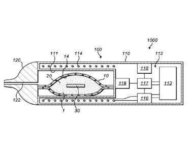
Referring to Figure 4 there is shown a schematic cross-sectional view of an
example of a system according to an embodiment of the invention. The system
1000 of
this embodiment comprises an article 1 comprising a malleable container 10
defining a
cavity 14, and a mass of smokable material 20 in the cavity 14, and apparatus
100 for
heating the smokable material 20 of the article 1 to volatilise at least one
component of
the smokable material 20. In this embodiment, the article 1 of the system 1000
is the
article 1 of Figure 1. However, in other embodiments, the article of the
system 1000
may be an article other than the article 1 of Figure 1, such as one of the
articles 2, 3 of
Figures 2 and 3. Broadly speaking, the apparatus 100 comprises a heating zone
111 for
receiving at least a portion of the article 1, 2, 3, and a magnetic field
generator 112 for
generating a varying magnetic field to be used in heating the smokable
material 20 when
the portion of the article 1, 2, 3 is in the heating zone 111.
The apparatus 100 of this embodiment comprises a body 110 and a mouthpiece
120. The mouthpiece 120 defines a channel 122 therethrough. The mouthpiece 120
is
locatable relative to the body 110 so as to cover an opening into the heating
zone 111.
When the mouthpiece 120 is so located relative to the body 110, the channel
122 of the
mouthpiece 120 is in fluid communication with the heating zone 111. In use,
the
channel 122 acts as a passageway for permitting volatilised material to pass
from the
cavity 14 of the article 1, 2, 3 inserted in the heating zone 111 to an
exterior of the
apparatus 100. In this embodiment, the mouthpiece 120 of the apparatus 100 is
releasably engageable with the body 110 so as to connect the mouthpiece 120 to
the
CA 03003521 2018-04-27
WO 2017/072148 PCT/EP2016/075738
body 110. In other embodiments, the mouthpiece 120 and the body 110 may be
permanently connected, such as through a hinge or flexible member. The
mouthpiece
120 of the apparatus 100 may comprise or be impregnated with a flavourant. The
flavourant may be arranged so as to be picked up by heated vapour as the
vapour passes
5 through the channel 122 of the mouthpiece 120 in use. In some
embodiments, such as
embodiments in which the article 1, 2, 3 itself comprises a mouthpiece, the
mouthpiece
120 of the apparatus 100 may be omitted.
In this embodiment, the body 110 comprises the heating zone 111. In this
10 embodiment, the heating zone 111 comprises a recess 111 for receiving at
least a portion
of the article 1. In other embodiments, the heating zone 111 may be other than
a recess,
such as a shelf, a surface, or a projection, and may require mechanical mating
with the
article 1, 2, 3 in order to co-operate with, or receive, the article 1, 2, 3.
In this
embodiment, the heating zone 111 is elongate, and is sized and shaped to
receive the
15 article 1. In this embodiment, the heating zone 111 accommodates the
whole article 1.
In other embodiments, the heating zone 111 may be dimensioned to receive only
a
portion of the article 1, 2, 3.
In some embodiments, the apparatus 100 may comprise a mechanism for
20 compressing an article 1, 2, 3 when the article 1, 2, 3 is located in
the heating zone 111.
Such compression of the article 1, 2, 3 may compress the smokable material 20,
so as
to increase the thermal conductivity of the smokable material 20. In other
words,
compression of the smokable material 20 can provide for higher heat transfer
through
the article 1, 2, 3. Such compression should not be so great as to burst or
break the
container 10 or to prevent a user to be able to draw volatilised material from
the article
1, 2, 3.
In this embodiment, the magnetic field generator 112 comprises an electrical
power source 113, a coil 114, a device 116 for passing a varying electrical
current, such
as an alternating current, through the coil 114, a controller 117, and a user
interface 118
for user-operation of the controller 117.
CA 03003521 2018-04-27
WO 2017/072148 PCT/EP2016/075738
21
In this embodiment, the electrical power source 113 is a rechargeable battery.
In other embodiments, the electrical power source 113 may be other than a
rechargeable
battery, such as a non-rechargeable battery, a capacitor, a battery-capacitor
hybrid, or a
connection to a mains electricity supply.
The coil 114 may take any suitable form. In this embodiment, the coil 114 is a
helical coil of electrically-conductive material, such as copper. In some
embodiments,
the magnetic field generator 112 may comprise a magnetically permeable core
around
which the coil 114 is wound. Such a magnetically permeable core concentrates
the
magnetic flux produced by the coil 114 in use and makes a more powerful
magnetic
field. The magnetically permeable core may be made of iron, for example. In
some
embodiments, the magnetically permeable core may extend only partially along
the
length of the coil 114, so as to concentrate the magnetic flux only in certain
regions.
In this embodiment, the coil 114 of the magnetic field generator 112 extends
along a longitudinal axis that is substantially coincident with a longitudinal
axis of the
heating zone 111. In other embodiments, these axes may be aligned with each
other by
being parallel to each other, or may be oblique to each other.
In this embodiment, an impedance of the coil 114 of the magnetic field
generator
112 is equal, or substantially equal, to an impedance of the body 30
comprising heating
material in the article 1. If the impedance of the body 30 of the article 1
were instead
lower than the impedance of the coil 114, then the voltage generated across
the body 30
of the article 1 in use may be lower than the voltage that may be generated
across the
body 30 of the article 1 when the impedances are matched. Alternatively, if
the
impedance of the body 30 of the article 1 were instead higher than the
impedance of the
coil 114, then the electrical current generated in the body 30 of the article
1 in use may
be lower than the current that may be generated in the body 30 of the article
1 when the
impedances are matched. In embodiments of the system 1000 comprising one of
the
articles 2, 3 of Figures 2 and 3, similarly the impedance of the coil 114 may
be equal,
or substantially equal, to an impedance of the part of the article 2, 3
comprising heating
material. Matching the impedances may help to balance the voltage and current
to
CA 03003521 2018-04-27
WO 2017/072148 PCT/EP2016/075738
22
maximise the heating power generated at the heating material of the article 1,
2, 3 when
heated in use.
In this embodiment, the device 116 for passing a varying current through the
coil 114 is electrically connected between the electrical power source 113 and
the coil
114. In this embodiment, the controller 117 also is electrically connected to
the
electrical power source 113, and is communicatively connected to the device
116 to
control the device 116. More specifically, in this embodiment, the controller
117 is for
controlling the device 116, so as to control the supply of electrical power
from the
.. electrical power source 113 to the coil 114. In this embodiment, the
controller 117
comprises an integrated circuit (IC), such as an IC on a printed circuit board
(PCB). In
other embodiments, the controller 117 may take a different form. In some
embodiments, the apparatus may have a single electrical or electronic
component
comprising the device 116 and the controller 117. The controller 117 is
operated in this
.. embodiment by user-operation of the user interface 118. In this embodiment,
the user
interface 118 is located at the exterior of the body 110. The user interface
118 may
comprise a push-button, a toggle switch, a dial, a touchscreen, or the like.
In other
embodiments, the user interface 118 may be remote and connected to the rest of
the
apparatus wirelessly, such as via Bluetooth.
In this embodiment, operation of the user interface 118 by a user causes the
controller 117 to cause the device 116 to cause an alternating electrical
current to pass
through the coil 114, so as to cause the coil 114 to generate an alternating
magnetic
field. When the article 1, 2, 3 is located in the heating zone 111, the coil
114 of the
apparatus 100 and the heating material of the article 1, 2, 3 are suitably
relatively
positioned so that the alternating magnetic field produced by the coil 114
penetrates the
heating material of the article 1, 2, 3. When the heating material of the
article 1, 2, 3 is
an electrically-conductive material, this may cause the generation of one or
more eddy
currents in the heating material. The flow of eddy currents in the heating
material
against the electrical resistance of the heating material causes the heating
material to be
heated by Joule heating. As mentioned above, when the heating material is made
of a
magnetic material, the orientation of magnetic dipoles in the heating material
changes
CA 03003521 2018-04-27
WO 2017/072148 PCT/EP2016/075738
23
with the changing applied magnetic field, which causes heat to be generated in
the
heating material.
The apparatus 100 of this embodiment comprises a temperature sensor 119 for
sensing a temperature of the heating zone 111. The temperature sensor 119 is
communicatively connected to the controller 117, so that the controller 117 is
able to
monitor the temperature of the heating zone 111. In some embodiments, the
temperature sensor 119 may be arranged to take an optical temperature
measurement of
the recess, heating zone or article 1, 2, 3. In some embodiments, the article
1, 2, 3 may
comprise a temperature detector, such as a resistance temperature detector
(RTD), for
detecting a temperature of the article 1, 2, 3. For example, the temperature
detector may
be located in or on the container 10 of the article 1, 2, 3. The article 1, 2,
3 may further
comprise one or more terminals connected, such as electrically-connected, to
the
temperature detector. The terminal(s) may be for making connection, such as
electrical
connection, with a temperature monitor of the apparatus 100 when the article
1, 2, 3 is
in the heating zone 111. The controller 117 may comprise the temperature
monitor.
The temperature monitor of the apparatus 100 may thus be able to determine a
temperature of the article 1, 2, 3 during use of the article 1, 2, 3 with the
apparatus 100.
In some embodiments, by providing that the heating material of the article 1,
2,
3 has a suitable resistance, the response of the heating material to a change
in
temperature could be sufficient to give information regarding temperature
inside the
article 1, 2, 3. The temperature sensor 119 of the apparatus 100 may then
comprise a
probe for analysing the heating material.
On the basis of one or more signals received from the temperature sensor 119
or
temperature detector, the controller 117 may cause the device 116 to adjust a
characteristic of the varying or alternating electrical cuiTent passed through
the coil 114
as necessary, in order to ensure that the temperature of the heating zone 111
remains
within a predetermined temperature range. The characteristic may be, for
example,
amplitude or frequency. Within the predetermined temperature range, in use the
smokable material 20 within an article 1, 2, 3 located in the heating zone 111
is heated
sufficiently to volatilise at least one component of the smokable material 20
without
CA 03003521 2018-04-27
WO 2017/072148 PCT/EP2016/075738
24
combusting the smokable material 20. Accordingly, the controller 117, and the
apparatus 100 as a whole, is arranged to heat the smokable material 20 to
volatilise the
at least one component of the smokable material 20 without combusting the
smokable
material 20. In some embodiments, the temperature range is about 50 C to about
300 C,
such as between about 50 C and about 250 C, between about 50 C and about 150
C,
between about 50 C and about 120 C, between about 50 C and about 100 C,
between
about 50 C and about 80 C, or between about 60 C and about 70 C. In some
embodiments, the temperature range is between about 170 C and about 220 C. In
other
embodiments, the temperature range may be other than this range. In some
embodiments, the temperature sensor 119 may be omitted.
The apparatus 100 may define an air inlet that fluidly connects the heating
zone
111 with the exterior of the apparatus 100. Such an air inlet may be defined
by the body
110 of the apparatus 100 and/or by the mouthpiece 120 of the apparatus 100. A
user
may be able to inhale the volatilised component(s) of the smokable material 20
by
drawing the volatilised component(s) through the channel 122 of the mouthpiece
120.
As the volatilised component(s) are removed from the cavity 14 of the
container 10 of
the article 1, 2, 3, such as through a porous portion of the container 10 or
through a hole
in the container 10 after the container has been punctured by a user, air may
be drawn
into the heating zone 111 via the air inlet of the apparatus 100.
The apparatus may provide haptic feedback to a user. The feedback could
indicate that heating is taking place, or be triggered by a timer to indicate
that greater
than a predetermined proportion of the original quantity of volatilisable
component(s)
of the smokable material 20 in the article 1, 2, 3 has/have been spent, or the
like. The
haptic feedback could be created by interaction of the coil 114 with the
heating material
of the article 1, 2, 3 (e.g. magnetic response), by interaction of an
electrically-conductive
element with the coil 114, by rotating an unbalanced motor, by repeatedly
applying and
removing a current across a piezoelectric element, or the like.
The apparatus 100 may comprise more than one coil. The plurality of coils of
the apparatus 100 could be operable to provide progressive heating of the
smokable
material 20 in an article 1, 2, 3, and thereby progressive generation of
vapour. For
CA 03003521 2018-04-27
WO 2017/072148 PCT/EP2016/075738
example, one coil may be able to heat a first region of the heating material
relatively
quickly to initialise volatilisation of at least one component of the smokable
material 20
and formation of a vapour in a first region of the smokable material 20.
Another coil
may be able to heat a second region of the heating material relatively slowly
to initialise
5
volatilisation of at least one component of the smokable material 20 and
formation of a
vapour in a second region of the smokable material 20. Accordingly, a vapour
is able
to be formed relatively rapidly for inhalation by a user, and vapour can
continue to be
formed thereafter for subsequent inhalation by the user even after the first
region of the
smokable material 20 may have ceased generating vapour. The initially-unheated
10 second region
of smokable material 20 could act as a heat sink, to reduce the
temperature of created vapour or make the created vapour mild, during heating
of the
first region of smokable material 20.
In some embodiments, the article 1, 2, 3 may comprise a plurality of discrete
15 portions of
heating material that is heatable by penetration with a varying magnetic field
to heat the smokable material 20 of the article 1, 2, 3. The plurality of
discrete portions
of heating material may be substantially separately heatable by varying
magnetic fields
produced by a respective plurality of coils 114 of the apparatus 100. One of
the plurality
of discrete portions of heating material may be more susceptible to eddy
currents being
20 induced
therein by penetration with a varying magnetic field than other(s) of the
plurality of discrete portions of heating material. Such a structure could be
operable to
provide progressive heating of the smokable material 20 in the article 1, 2,
3, and
thereby progressive generation of vapour, in a similar way to that described
above.
25 In each of
the embodiments discussed above, the heating material may have a
skin depth, which is an exterior zone within which most of an induced
electrical current
and/or induced reorientation of magnetic dipoles occurs. By providing that the
component comprising the heating material has a relatively small thickness, a
greater
proportion of the heating material may be heatable by a given varying magnetic
field,
as compared to heating material in a component having a depth or thickness
that is
relatively large as compared to the other dimensions of the component. Thus, a
more
efficient use of material is achieved. In turn, costs are reduced.
CA 03003521 2018-04-27
WO 2017/072148 PCT/EP2016/075738
26
In some embodiments, a component comprising the heating material may
comprise discontinuities or holes therein. Such discontinuities or holes may
act as
thermal breaks to control the degree to which different regions of the
smokable material
20 are heated in use. Areas of the heating material with discontinuities or
holes therein
may be heated to a lesser extent that areas without discontinuities or holes.
This may
help progressive heating of the smokable material 20, and thus progressive
generation
of vapour, to be achieved. Such discontinuities or holes may, on the other
hand, be used
to optimise the creation of complex eddy currents in use.
In each of the above described embodiments, the smokable material 20
comprises tobacco. However, in respective variations to each of these
embodiments,
the smokable material 20 may consist of tobacco, may consist substantially
entirely of
tobacco, may comprise tobacco and smokable material other than tobacco, may
comprise smokable material other than tobacco, or may be free of tobacco. In
some
embodiments, the smokable material 20 may comprise a vapour or aerosol forming
agent or a humectant, such as glycerol, propylene glycol, triacetin, or
diethylene glycol.
An article embodying the present invention may be a cartridge, for example.
In each of the above described embodiments, the article 1, 2, 3 is a
consumable
article. Once all, or substantially all, of the volatilisable component(s) of
the smokable
material 20 in the article 1, 2, 3 has/have been spent, the user may remove
the article 1,
2, 3 from the apparatus and dispose of the article 1, 2, 3. The user may
subsequently
re-use the apparatus with another of the articles 1, 2, 3. However, in other
respective
embodiments, the article 1, 2, 3 may be non-consumable, and the apparatus and
the
article 1, 2, 3 may be disposed of together once the volatilisable
component(s) of the
smokable material 20 has/have been spent.
In some embodiments, the apparatus discussed above is sold, supplied or
otherwise provided separately from the articles 1, 2, 3 with which the
apparatus is
usable. However, in some embodiments, the apparatus and one or more of the
articles
1, 2, 3 may be provided together as a system, such as a kit or an assembly,
possibly with
additional components, such as cleaning utensils.
WO 2017/072148 PCT/EP2016/075738
27
'he invention could be implemented in a system comprising any one of the
articles discussed herein, and any one of the apparatuses discussed herein,
wherein the
apparatus itself has heating material, such as in a susceptor, for heating by
penetration
with the varying magnetic field generated by the magnetic field generator.
Heat
generated in the heating material of the apparatus could be transferred to the
article to heat,
or further heat, the smokable material 20 therein when the portion of the
article is in the
heating zone Ill. In some such embodiments, the article may be free of heating
material, so
that the smokable material 20 of the article is heated only by the heat
transferred to the article from the heating material of the apparatus.
In order to address various issues and advance the art, the entirety of this
disclosure
shows by way of illustration and example various embodiments in which the
claimed
invention may be practised and which provide for superior articles for use
with
apparatus for heating smokable material to volatilise at least one component
of the
smokable material, and superior systems comprising such apparatus and such
articles. The
advantages and features of the disclosure are of a representative sample of
embodiments
only, and are not exhaustive and/or exclusive. They are presented only to
assist in
understanding and teach the claimed and otherwise disclosed features. It is
to be understood that advantages, embodiments, examples, functions, features,
structures and/or other aspects of the disclosure are not to be considered
limitations on the
disclosure. Various embodiments may suitably comprise, consist of, or consist
in essence of,
various combinations of the disclosed elements, components, features, parts,
steps, means.
etc. The disclosure may include other inventions not presently claimed, but
which may be
claimed in future.
CA 3003521 2019-09-24