Note: Descriptions are shown in the official language in which they were submitted.
METHOD TO MEASURE AIRCRAFT HIGH-LIFT SYSTEM BRAKE RESPONSE
TIME
TECHNICAL FIELD
[0001] This disclosure relates to a method for testing a component in a high =
lift system of an aircraft, a high lift system of an aircraft as well as an
aircraft having
at least one such high lift system. The disclosure can also be applicable to
other
systems including, but not limited to, horizontal stabilizers, utility
actuators, and the
like, which rely on a brake response time as a critical function of its
operating
performance.
BACKGROUND
[0002] Typically, high lift systems of commercial and military aircraft are
powered by a centralized drive, also known as a power drive unit (PDU). Such
drives
are mounted in a central region of the fuselage and are controllable through a
computerized control system or electronics unit. The PDU is coupled with a
torque
shaft system, also known as transmission shaft, which transfers mechanical
power to
geared actuators at flap or slat panel drive stations distributed along the
trailing edge
or leading edge of a wing. The control of the PDU is usually conducted by
control
computers, such as slat flap electronic control computers/unit (SFECU), which
are
commonly realized as a redundant arrangement of at least two independent
SFECUs
that are not only able to control but also to monitor the operation of the
high lift
system.
[0003] The PDU commonly comprises two independent motors that may be
hydraulic or electric, which may be coupled with an output shaft by means of a
speed
summing differential gear. Each of the motors is provided with a power off
brake
(POB) for arresting the motor in a commanded position. In some systems, while
at
least one of the two motors is commonly a hydraulic motor, the second motor
may be
realized as an electric motor, leading to a hybrid PDU. A wing tip brake,
which is
coupled with the transmission shaft and particularly placed in an outer region
of the
CA 3003531 2018-05-01
transmission shaft and/or in a tip region of the respective wing, is also
capable of
arresting and holding the transmission shaft. Each of the wing tip brakes are
power
off brake (POB) which arrest the system in an existing position.
[0004] Still further, high lift systems usually comprise torque limiters that
are
adapted for limiting the torque to be introduced into the transmission system.
The
torque limiters may be mechanical or electronic torque limiters, wherein the
latter rely
on constantly monitoring an introduced torque, taking authority over the
motors of the
-PDU, and initiating limitation and/or a reversal once the torque exceeds a
predetermined threshold. The torque limiters can be separate elements or
integrated
into the PDU.
[0005] High-lift systems often rely on specific brake engagement response
times to mitigate failure scenarios such as un-commanded motion, asymmetry and
flap/slat panel skew. In such failure scenarios if a monitored parameter of
the system
is found to be out of an acceptable range, the high-lift system annunciates
the failure
condition and commands the system brakes to engage preventing further motion.
System parameters and functions such as threshold values, fault monitoring,
fault
persistence, brake electrical control circuits, and the brake itself all
contribute to the
overall response time of the brake to arrest the system. Moreover, brake
systems can
develop degraded performance over life due to electrical variations,
mechanical wear
and environmental exposure all of which will increase the brake's engagement
response time. Degraded brake response times may prevent or degrade a high-
lift
system from mitigating a given failure scenario resulting in risk to the
aircraft. As
such, the need for a method to measure a high-lift system's brake response
time to
arrest motion as a system without the need for ground test equipment would be
a
useful tool in mitigating certain failure modes.
BRIEF DESCRIPTION
[0006] According to one embodiment of the invention, described herein is a
braking test for a high lift system. The system including a plurality of high
lift
surfaces movably arranged at a wing, a plurality of drive stations coupled
with the
2
CA 3003531 2018-05-01
high lift surfaces via a transmission shaft, a power drive unit coupled with
the
transmission shaft including an electric motor operably coupled with a brake,
and a
control unit operably coupled to the power drive unit. The control unit
executing a
method for testing the brake, including actuating an electric motor, acquiring
a sensor
output of a sensor coupled during the actuating of the motor and determining a
motion
of the motor, activating a selected brake under test, measuring an elapsed
time until
the brake has arrested the motion, and determining if the elapsed time is less
than a
threshold. Generating a brake failure signal for the selected brake if the
elapsed time
exceeds the threshold.
[0007] A method for testing a component in a high lift system of an aircraft.
The high lift system comprising a central power drivt., unit for moving high
lift
surfaces arranged at a wing through providing rotational power by means of a
transmission shaft to a plurality of drive stations operably coupled with the
high lift
surfaces; which power drive unit is operatively coupled to a controller and
comprises
at least one electric motor coupled with a selectively activated brake. The
method
including actuating the at least one electric motor for a predetermined period
of time
with all brakes in the system deactivated, acquiring a sensor output of a
sensor
coupled with the controller during the actuating of the motor and determining
a
motion of at least one of the motor and the high lift surfaces based on the
acquired
sensor output, activating a selected brake under test, measuring an elapsed
time until
the selected brake has arrested the motion of at least one of the motor and
the high lift
surfaces, determining if the that the elapsed time is less than a
predetermined
threshold value, and generating a brake failure signal for the selected brake
if the
elapsed time exceeds the predetermined threshold value.
[0008] In addition to one or more of the features described above, or as an
alternative, further embodiments may include moving the high lift surfaces to
a
selected position before activating the selected brake.
[0009] In addition to one or more of the features described above, or as an
alternative, further embodiments may include that the selected position is at
least one
of a fully extended positon and a neutral position.
3
CA 3003531 2018-05-01
[0010] In addition to one or more of the features described above, or as an
alternative, further embodiments may include conducting at least one of a
system
functional test, power on reset built in test, and an initiated built in test.
[0011] In addition to one or more of the features described above, or as an
alternative, further embodiments may include at least one of ensuring
established
preconditions for conducting the testing have been satisfied defining maximum
torque
for a selected brake under test, and releasing all system brakes.
[0012] In addition to one or more of the features described above, or as an
alternative, further embodiments may include that the activating the brake is
conducted a selected duration after the actuating the at least one electric
motor.
[0013] In addition to one or more of the features described above, or as an
alternative, further embodiments may include that the selected duration is at
least
TBD seconds.
[0014] In addition to one or more of the features described above, or as an
alternative, further embodiments may include that the acquiring includes
measuring at
least one of a displacement and a speed of the high lift surface based on the
actuation
of the motor.
[0015] In addition to one or more of the features described above, or as an
alternative, further embodiments may include that the selected threshold is
less than at
least one of about TBD seconds and about TBD seconds.
[0016] In addition to one or more of the features described above, or as an
alternative, further embodiments may include repeating the method for another
brake
in the high lift system.
[0017] In addition to one or more of the features described above, or as an
alternative, further embodiments may include that the method is conducted
after
landing of the aircraft while at least one of the high lift surfaces are in an
extended
position and the high lift surfaces are moved into a neutral position.
4
CA 3003531 2018-05-01
[0018] Also described herein in an embodiment is a high lift system of an
aircraft, including a plurality of high lift surfaces movably arranged at a
wing, a
plurality of drive stations coupled with the high lift surfaces a transmission
shaft
coupled with the plurality of drive stations a power drive unit coupled with
the
transmission shaft for moving the high lift surfaces, the power drive unit
comprising
at least one electric motor operably coupled and with a brake, and a control
unit. The
control unit operably coupled to the power drive unit, the control unit
configured to
execute a method for testing a component in a high lift system of an aircraft.
The
method including, actuating the at least one electric motor for a
predetermined period
of time with all brakes deactivated, acquiring a sensor output of a sensor
coupled with
the controller during the actuating of the motor and determining a motion of
at least
one of the motor and the high lift surfaces based on the acquired sensor
output,
activating a selected brake under test, measuring an elapsed time until the
brake has
arrested the motion, and determining if the elapsed time is less than a
predetermined
threshold value, and generating a brake failure signal for the selected brake
if the
elapsed time exceeds the predetermined threshold value.
[0019] In addition to one or more of the features described above, or as an
alternative, further embodiments may include the controller executing a
previous step
of moving the high lift surfaces to a selected position before activating the
at least one
brake.
[0020] In addition to one or more of the features described above, or as an
alternative, further embodiments may include the controller executing a step
of
conducting at least one of a system functional test, powei on reset built in
test, and an
initiated built in test.
[0021] In addition to one or more of the features described above, or as an
alternative, further embodiments may include that the activating the brake is
conducted a selected duration after the actuating the at least one electric
motor.
CA 3003531 2018-05-01
[0022] In addition to one or more of the features described above, or as an
alternative, further embodiments may include that the selected duration is at
least
TBD seconds.
[0023] In addition to one or more of the features described above, or as an
alternative, further embodiments may include that the acquiring includes
measuring at
least one of a displacement and a speed of the high lift surface based on the
actuation
by the motor.
[0024] In addition to one or more of the features described above, or as an
alternative, further embodiments may include that the selected threshold is
less than at
least one of about TBD seconds, about TBD seconds, and about TBD seconds.
[0025] In addition to one or more of the features described above, or as an
alternative, further embodiments may include that the method is conducted
after
landing of the aircraft while at least one of the high lift surfaces are in an
extended
position and the high lift surfaces are moved into a neutral position.
[0026] In addition to one or more of the features described above, or as an
alternative, further embodiments may include that the high lift surfaces are
at least
one of trailing edge flaps and leading edge slats.
[0027] In addition to one or more of the features described above, or as an
alternative, further embodiments may include that the control unit is
integrated into a
control computer for controlling the high lift surfaces.
[0028] Additional features and advantages are realized through the techniques
of the present disclosure. Other embodiments and aspects of the disclosure are
described in detail herein. For a better understanding of the disclosure with
the
advantages and the features, refer to the description and to the drawings.
BRIEF DESCRIPTION OF THE DRAWINGS
[0029] The subject matter which is regarded as the invention is particularly
pointed out and distinctly claimed in the claims at the conclusion of the
specification.
6
CA 3003531 2018-05-01
The foregoing and other features, and advantages of the invention are apparent
from
the following detailed description taken in conjunction with the accompanying
drawings in which:
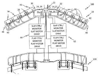
[0030] FIG. 1 depicts a simplified system schematic of high-lift system on an
aircraft as employed in the embodiments; and
[0031] FIG. 2 is a flowchart of methods of measuring high-lift brake response
time in accordance with an embodiment.
DETAILED DESCRIPTION
[0032] For the purposes of promoting an understanding of the principles of the
present disclosure, reference will now be made to the embodiments illustrated
in the
drawings, and specific language will be used to describe the same. It will
nevertheless be understood that no limitation of the scope of this disclosure
is thereby
intended. The following description is merely illustrative in nature and is
not
intended to limit the present disclosure, its application or uses. It
should be
understood that throughout the drawings, corresponding reference numerals
indicate
like or corresponding parts and features. As used herein, the term controller
refers to
processing circuitry that may include an application specific integrated
circuit (ASIC),
an electronic circuit, an electronic processor (shared, dedicated, or group)
and
memory that executes one or more software or firmware programs, a
combinational
logic circuit, and/or other suitable interfaces and components that provide
the
described functionality.
[0033] Additionally, the term "exemplary" is used herein to mean "serving as
an example, instance or illustration." Any embodiment or design described
herein as
"exemplary" is not necessarily to be construed as preferred or advantageous
over
other embodiments or designs. The terms "at least one" and "one or more" are
understood to include any integer number greater than or equal to one, i.e.
one, two,
three, four, etc. The terms "a plurality" are understood to include any
integer number
greater than or equal to two, i.e. two, three, four, five, etc. The term
"connection" can
include an indirect "connection" and a direct "connection".
7
CA 3003531 2018-05-01
[0034] As shown and described herein, various features of the disclosure will
be presented. Various embodiments may have the same or similar features and
thus
the same or similar features may be labeled with the same reference numeral,
but
preceded by a different first number indicating the figure to which the
feature is
shown. Thus, for example, element "a" that is shown in Figure X may be labeled
"Xa" and a similar feature in Figure Z may be labeled "Za." Although similar
reference numbers may be used in a generic sense, various embodiments will be
described and various features may include changes, alterations,
modifications, etc. as
will be appreciated by those of skill in the art, whether explicitly described
or
otherwise would be appreciated by those of skill in the art.
[0035] In general, embodiments herein relate generally to a system level
approach to test and detect that the brake response time in a high-lift system
has
exceeded allowable limits. Advantageously the described embodiments employ an
automated system level Built In Test (BIT) methodology eliminating the need
for
ground test equipment. Furthermore, the described embodiments consider all
system
level components that may contribute to the brake response time, whereas
conventional brake response test methods typically measure only the
contribution
from the mechanical brake.
[0036] In FIG. 1, a general setup of a high lift system 100 is shown in an
exemplary leading edge slat system 20 and trailing edge flap system 120. While
the
description provided herein and depicted in FIG. 1 is directed to an exemplary
leading
edge slat system, it should be readily appreciated that it is equally
applicable to the
trailing edge flap system 120 without any loss of generality. For better
understanding
of the described embodiments and simplification of the figures and description
further
detail with respect to the trailing edge flap system 120 has been omitted to
avoid
repetition.
[0037] A power drive unit (PDU) 22 comprises a plurality of electric motors
24, 25 or hydraulic motors. In an embodiment two electric motors 24, 25 are in
employed on each PDU 22, but various numbers of motors may be employed
depending on the needs of the application. Further, in an embodiment, while
electric
8
CA 3003531 2018-05-01
motors are described. It should also be appreciated that the description
provided
herein is equally applicable to hydraulic motors without any loss of
generality. A
power off brake 26, 27 is coupled with each of the electric motor(s) 24, 25
respectively, as a means to stop and maintain PDU output. The PDU outputs are
coupled, through the PDU, to a transmission shaft systehi 30, 32 that extends
along
the leading edge of each wing. Each of the transmission shafts 30, 32 is
coupled with
several drive stations 34 distributed along the respective wing half, wherein
each of a
plurality of movably supported high lift surfaces 36 is driven by two or more
individual drive stations 34. In the figure, four high lift surfaces 36 (e.g.,
slats) are
depicted for each wing half, though any number may be employed.
[0038] Each of the transmission shafts 30, 32 also includes a wing tip brake
40, 42 in a region around the outer end of each of the shafts 30, 32, which
may be at
an outer end of the respective wing. Typically, the location of the wingtip
brake 40,
42, is at the end of the driveline. However, some applications may require the
wingtip
brake 40, 42 to be installed inboard of the most outboard actuator due to
restrictions in
envelope, structure, and the like at the end of the wing. Also, each
transmission shaft
30, 32 is exemplarily coupled with an position sensor 44, 46 arranged at an
outermost
end of the respective shaft 30, 32 providing position feedback of the system
and
allowing the detection of asymmetry conditions between both transmission
shafts 30,
32 and, respectively, the drive stations 34 of both wing halves.
[0039] The system 100 may further comprise a feedback position sensor or
pickoff unit 52, 54 that allows monitoring the of the transmission shafts 30,
32 at or
near the output of the PDU 22. Torque sensor units 56, 58 arranged at the
transmission shafts 30, 32 or within the PDU 22, monitor the torque that is
introduced
into the transmission shafts 30, 32. All of the position pickoff units 44, 46,
the
feedback position pickoff unit 52, 54, and the torque sensor units 56, 58 are
coupled
with two control units 60, 62, which are exemplarily realized as a first slat
flap
electronic control unit (SFECU) 60 and a second SFECU 62. While identified
separately for the purposes of description of the embodiments herein, it
should be
appreciated that the PDU 22 and SFECU 60, 62 could be integrated or their
functions
redistributed. The
torque in the transmission shafts 30, 32 of each wing is
9
CA 3003531 2018-05-01
exemplarily limited through a torque limiter (TL) functionality, in which the
torque
sensor units 54, 56 detect the introduced torque. If the torque in one of the
transmission shafts 30, 32 exceeds a certain torque threshold the PDU 22 is
either
stopped or, in some embodiments, a rapid speed decrease or reversal of the PDU
motors is conducted, leading to controlling the torque to an uncritical level.
Finally
the system 100 may be arrested through engaging the brake 26, 27 associated
with
each of the motors 24, 25 and the asymmetry brakes 40, 42. The electric motors
24,
25 may be a brushless direct current (BLDC) motors controlled through a
digital drive
control, coupled with the SFECUs 60 and 62.
[0040] In a default high lift operating mode, the wing tip brakes 40, 42 and
motor brakes 26, 27 are released and the motors 24, 25, controlled by SFECUs
60,
62, provides power to the PDU 22, which provides sufficient mechanical power
to
operate the high lift system 100 at a commanded speed into any commanded
position.
Once near the commanded position the SFECUs 60, 62 decelerate the motors 24,
25
reducing the output of the PDU 22 to decelerate the high lift system 100. Once
at the
commanded position the system brakes 26, 27 are engaged to stop and hold the
position of the high lift system 100.
[0041] Turning now to FIG.2 for depiction of the method 200 of measuring
aircraft high lift system brake response time in accordance with an
embodiment. In
order to conduct the brake response time testing of the methodology 200 the
proper
function and operation of the high-lift system is first verified employing a
standard
functional, operational or acceptance test as depicted at optional process
step 205. It
should be appreciated that while it is not necessary to conduct the system
function test
prior to brake response time testing, conducting functional test of the system
is
advantageous to ensuring accurate results without erroneous failures. In
addition,
conducting a system operation test first facilitates trouble shooting to
identify the root
cause of a system failure. Such testing of the various components and
contributors of
the high-lift system 100 may be conducted via existing testing techniques
including
standard power on reset BIT (PORBIT) or more extensively based on a ground
based
initiated built in test IBIT. In an embodiment the testing described could be
conducted once an aircraft has landed (weight on wheels).
CA 3003531 2018-05-01
[0042] In operation this testing may be conducted as part of a standard ground
BIT. In another embodiment, the method may be integrated with a common
functional sequence in operation. For example in an embodiment, the method 200
may be conducted directly after landing, when the high lift surfaces 36 are
still
extended as depicted in process step 310. Other conditions for engaging the
test
might include aircraft weight on wheels, and airspeeds less than a selected
value, e. g.,
<50 knots. For example, in an embodiment, a normal system command is received
to
return the wing high lift surface to the retracted position. The system would
respond
normally to the command as depicted in process step 205. The motion (all
system
brakes 26, 27, 40, and 42 are released and the motor is operating at normal
rate) will
continue until the system reaches the commanded position. Once near the
commanded position the torque maximum torque output for the brake under test
is
determined and output by the SFECUs 60, 62.
[0043] The method 200 may be used to test power drive motor brakes 26, 27
or asymmetry brakes 40, 42. In an embodiment the method 200 is executed in the
SFECU 60 and/or 62, respectively when preconditions for the test are
satisfied. The
preconditions may be optional or required to establish that the aircraft
conditions are
acceptable for the test to be conducted, typically ground maintenance mode,
and there
are no human factor risks, depicted as process step 210.
[0044] Once the preconditions are satisfied SFECUs 60 and 62 conducts a
sequence of steps for each of the system brakes. The first step, depicted at
process
step 215 is to optionally establish a selected maximum system torque value for
testing
the brake under test, which ensures the brake under test (motor brake 26, 27
or
asymmetry brakes 40, 42) or other aircraft components will not be mechanically
damaged due to conducting the rate response testing of the method 200. At
process
step 220 all of the system brakes are released, allowing high lift system 100
and
actuators 24, 25 to be moved. With the system brakes 26, 27, 40, 42 released
the
motor drive in the PDU 22 is commanded to move the system at a rate sufficient
to
determine brake response time, as depicted in process step 225. After some
delay to
ensure the motors are moving at full speed, but well within the range of
travel of the
system, the test of the brake response time of a first brake under test
(e.g.one of motor
11
CA 3003531 2018-05-01
brakes 26, 27 or asymmetry brakes 40, 42) is initiated. In one embodiment, the
delay
is about one or two seconds is employed.
[0045] At the position where brakes are to be engaged to stop and hold the
system only the brake under test is commanded to engage. While monitoring
system
speed via a position feedback sensor 52 or 54, the brake under test is
commanded to
engage as depicted in process step 230. The commands can come from the SFECS
60
and/or 62. At process step 235 of the method 200 the speed of the system is
recorded
and monitored between the time starting from the brake engagement in process
step
230 (time zero) until the system comes to stop is measured. Once the system is
stopped by the brake under test or a maximum response time is exceeded all of
the
system brakes are engaged and the motor drive commands are removed as depicted
in
process step 240. If the detected motion exceeds an application specific
threshold,
e.g. a rotation of the motor 22 in the PDU 22, a brake indication signal is
generated.
The commandment of the motor 24, 25, may be conducted for a couple of seconds,
e.g. 3, 4 or 5 seconds, which allows to reliably identify any dormant
undesired
condition of the power off brake 26, 27. In an embodiment, the threshold is
application specific depending on the system, the actuator and its
configuration, and
the brake being tested. Different system and aircraft configurations may
require
different thresholds. Ultimately what is desired is that the brake arrests
motion prior
to the high lift control surface 36 e.g., a flap or slat moving an
objectionable amount.
One measure of an objectionable amount would be if the control surface moved
enough to impact aircraft handling or flying quality.
[0046] The steps depicted in process steps 210 through 240 are repeated for
the remaining system brakes until all system brakes are tested. Once all
system
brakes are tested, process step 250 evaluates if the engagement time for each
system
brake is within the allowable limits required. Any brake which does not engage
in the
application specific amount of time is identified as failed and requires
further
maintenance or replacement prior to the next dispatch of the aircraft.
[0047] Continuing with FIG. 2, one method is identified, in an embodiment, to
facilitate performing the test, one method employed is asing a maintenance
mode.
12
CA 3003531 2018-05-01
Other embodiments could be to simulate an out-of-acceptable range sensor
parameter
to a system monitor function of the SFECS 60 and/or 62 such that a system shut
down
is annunciated. In one embodiment, the point in time which the out of range
parameter is simulated is recorded as time "zero". In an embodiment an
asymmetric
condition is simulated by adjusting a wingtip position sensor parameter,
however
other high-lift system parameters such as skew sensor displacement, and the
like may
also be employed. With the simulated out of range parameter the high-lift
system 100
in response annunciates a failure and the SFECS 60 and/or 62 commands the
brakes
26, 27, 40, and 42 to arrest the actuation in the system 100. While monitoring
the
movement of the motor 24, 25 and high lift surfaces 36 driven by drive
stations 34,
the method 200 continues with process step 235 by monitoring and recording the
elapsed time and displacement when the system (i.e., the surfaces 36) reach
zero
speed and monitoring the current waveforms of each brake to identify the EMF
of the
solenoid as it moves within the brake coil. As depicted at process step 230,
the total
elapsed time for motion to stop and/or for each brake solenoid to engage is
verified
against requirements for the high-lift system 100 to ensun that the system is
operating
with specifications.
[0048] The terminology used herein is for the purpose of describing particular
embodiments only and is not intended to be limiting of the invention. As used
herein,
the singular forms "a", "an" and "the" are intended to include the plural
forms as well,
unless the context clearly indicates otherwise. It will be further understood
that the
terms "comprises" and/or "comprising," when used in this specification,
specify the
presence of stated features, integers, steps, operations, elements, and/or
components,
but do not preclude the presence or addition of one more other features,
integers,
steps, operations, element components, and/or groups thereof.
[0049] The corresponding structures, materials, acts, and equivalents of all
means or step plus function elements in the claims below are intended to
include any
structure, material, or act for performing the function in combination with
other
claimed elements as specifically claimed. The description of the present
invention has
been presented for purposes of illustration and description, but is not
intended to be
exhaustive or limited to the invention in the form disclosed. Many
modifications and
13
CA 3003531 2018-05-01
variations will be apparent to those of ordinary skill in the art without
departing from
the scope and spirit of the invention. The embodiment was chosen and described
in
order to best explain the principles of the invention and the practical
application, and
to enable others of ordinary skill in the art to understand the invention for
various
embodiments with various modifications as are suited to the particular use
contemplated.
14
CA 3003531 2018-05-01